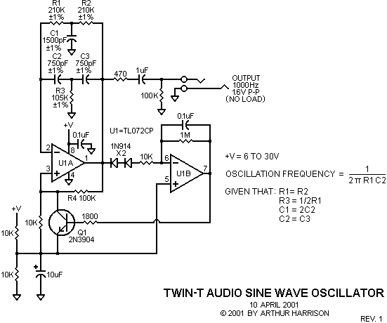
Twin-T Audio Sine Wave Oscillator
This circuit produces a clean sine wave signal ideal for audio testing, or wherever a good-quality sine voltage source is required. It uses only one integrated circuit which is a common dual operational amplifier, the Texas Instruments TL072CP. The values shown provide an output frequency of about 1000 Hertz. This frequency may be varied over a wide range, using the formula shown in the schematic. For most audio frequencies, the oscillation rate is almost exclusively determined by the twin-T network in U1A's feedback loop, provided that the gain-bandwidth product and slew rate specifications for the op amp are sufficiently high. For frequencies exceeding 10kHz, an faster op-amp in the U1A position is recommended.
The ratios of the resistors and capacitors in the twin-T network must be accurate to ensure oscillation. For that reason, ±1% components are indicated. The resistors in the twin-T network should be metal film, and the capacitors mica (best), polystyrene (good), or C0G ceramic (sufficient). Polyester capacitors may be used for economy if large C1, C2, and C3 values, such as those exceeding 10,000pF, are required. Note that the capacitor ratio of 2:1 is most conveniently obtained with the standard values that have this nominal relationship, e.g., 750pF and 1500pF, as shown in the schematic. Other useful combinations include 1000pF and 2000pF, 1100pF and 2200pF, 1500pF and 3000pF, and 1800 and 3600pF. Alternatively, four equivalent capacitors may be used, with two of them paralleled to make C1. This technique has the advantage that capacitors from the same lot are more likely to be closer in value. The same technique is also applicable for the three resistors, especially when an exact 2:1 ratio of resistance values is not available.
Operation of this oscillator is unconventional, in that the frequency-selective network is in the negative feedback path of the operational amplifier. The positive feedback required for oscillation is provided by R4. Transistor Q1 is part of an automatic gain control (AGC) servo that regulates the positive feedback to keep the sine wave output at a consistent amplitude.
With transistor Q1 and resistor R4 omitted, U1A's transfer function from its positive input to output is a notch filter with a frequency and depth determined by the twin-T component values. The addition of Q1 and R4 provides U1A positive feedback with zero degrees of phase shift at the notch frequency. The circuit will therefore oscillate at this frequency when Q1's emitter-to-collector resistance (Rec) is such that:
(R4 + Rec) / Rec (expressed in dB) =
U1A's open-loop gain (expressed in dB) -
the magnitude of the notch depth (expressed in dB)
U1B and its associated components complete the AGC servo. The series-connected diodes provide negative peak-level detection of the sine wave voltage and also determine the amplitude of the output. Q1 is operated close to maximum conduction, so the small voltage from its emitter to collector contributes negligible distortion to the sine wave. The 0.1uF integrating capacitor in U1B's feedback path was chosen to provide adequate AGC-loop stability for the selected oscillation frequency. The 10K resistor in parallel with Q1 ensures start-up.
The oscillator's amplitude, as well as frequency, is essentially independent of the power supply voltage. An output amplitude of 1.6 volts, peak-to-peak, was chosen to accommodate power supply voltages as low as 6 volts. Replacing the TL072CP with a rail-to-rail dual operational amplifier such as the Analog Devices type AD823AN will permit operation from even lower supply voltages, such as 4 volts. The oscillator will operate conveniently from a single 9-volt battery, and consumes less than 5 milliamperes of current when using the TL072CP. The 470 ohm resistor in the output prevents instabilities from capacitive loads such as long cables, and the 1uF capacitor removes the DC term at U1A. The output's 100K resistor discharges the 1uF capacitor to prevent voltage transients when connecting a load.
Acknowledgement
The author gratefully acknowledges Rick Hansen for providing an analysis of this circuit's operation.

April 12, 2001
Text and images ©2001 by Arthur Harrison
Back to the Circuit Library Index
Back to the Opening Page of Art's Theremin Page