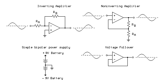
Inverting Amplifier:
The op-amp is connected using two resistors RA and RB such that the input signal is applied in series with RA and the output is connected back to the inverting input through RB. The noninverting input is connected to the ground reference or the center tap of the dual polarity power supply. In operation, as the input signal moves positive, the output will move negative and visa versa. The amount of voltage change at the output relative to the input depends on the ratio of the two resistors RA and RB. As the input moves in one direction, the output will move in the opposite direction, so that the voltage at the inverting input remains constant or zero volts in this case. If RA is 1K and RB is 10K and the input is +1 volt then there will be 1 mA of current flowing through RA and the output will have to move to -10 volts to supply the same current through RB and keep the voltage at the inverting input at zero. The voltage gain in this case would be RB/RA or 10K/1K = 10. Note that since the voltage at the inverting input is always zero, the input signal will see a input impedance equal to RA, or 1K in this case. For higher input impedances, both resistor values can be increased.
Noninverting Amplifier:
The noninverting amplifier is connected so that the input signal goes directly to the noninverting input (+) and the input resistor RA is grounded. In this configuration, the input impedance as seen by the signal is much greater since the input will be following the applied signal and not held constant by the feedback current. As the signal moves in either direction, the output will follow in phase to maintain the inverting input at the same voltage as the input (+). The voltage gain is always more than 1 and can be worked out from Vgain = (1+ RB/RA).
Voltage Follower:
The voltage follower, also called a buffer, provides a high input impedance, a low output impedance, and unity gain. As the input voltage changes, the output and inverting input will change by an equal amount.

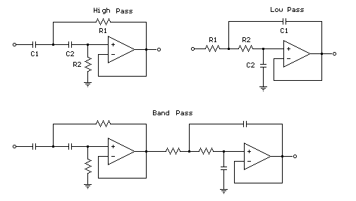
First order low or high pass cutoff frequency (-3dB point) = 1/(2pi*R*C)
2nd order low or high pass cutoff frequency (-3dB point) = 1/2pi(R1*R2*C1*C2)^.5
Example for 2Khz cutoff frequency - R1=R2=7.95K, C1=C2=0.1uF

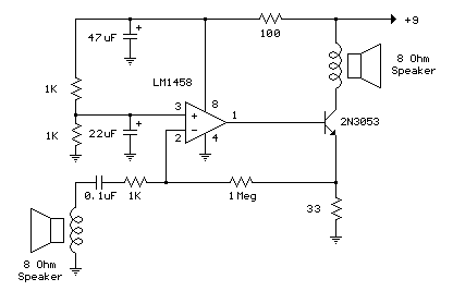
The example below illustrates using an op-amp as an audio amplifier for a simple intercom. A small 8 ohm speaker is used as a microphone which is coupled to the op-amp input through a 0.1uF capacitor. The speaker is sensitive to low frequencies and the small value capacitor serves to attenuate the lower tones and produce a better overall response. You can experiment with different value capacitors to improve the response for various speakers. The op-amp voltage gain is determined by the ratio of the feedback resistor to the series input resistor which is around one thousand in this case (1 Meg / 1K). The non-inverting input (pin 3) to the op-amp is biased at 50% of the supply voltage (4.5 volts) by a couple 1K resistors connected across the supply. Since both inputs will be equal when the op-amp is operating within it's linear range, the voltage at the non-inverting input (pin 2) and the emitter of the buffer transistor (2N3053) will also be 4.5 volts. The voltage change at the emitter of the transistor will be around +/- 2 volts for a 2 millivolt change at the input (junction of 0.1 cap and 1K resistor) which produces a current change of about 2/33 = 60 mA through the 33 ohm emitter resistor and the speaker output. The peak output speaker power is about I^2 * R or .06 ^2 * 8 = 28 milliwatts. The 100 resistor and 47uF capacitor are used to isolate the op-amp from the power supply and reduce the possibility of oscillation. An additional 22uF cap is used at the non-inverting input to further stabilize operation. These parts may not be needed in such a low power circuit but it's a good idea to decouple the power supply to avoid unwanted feedback. The circuit draws about 1.2 watts from a 9 volt source and is not very efficient but fairly simple to put together. The circuit was tested using a couple 4 inch speakers located a few feet apart (to reduce feedback) and a small pocket transistor radio placed on top of the speaker/microphone as an audio source.
