Toggle Switch Debounced Pushbutton
John Lundgren 12-7-96 V961208a
(ASCII schematic and togl01.jpg below)
This is a unique and interesting circuit that I found somewhere.
It's a simple circuit that has two characteristics. It debounces
the pushbutton switch with just a few parts. It also always comes
up reset so that Q1 is on and Q2 is off.
The circuit is a two transistor bistable flip-flop. The
pushbutton switch toggles by either charging or discharging the
C1, the 1 uF capacitor, thru the base of Q1, with current limited
by the 330 ohm resistor. The circuit comes up reset, with Q1 on
and Q2 off. So after a second or so, C1 is discharged thru the 1M
resistor. When the push button is pressed, C1 is charged thru the
330 ohm R2, and toggles the flip-flop. Q1 is then off and Q2 is
saturated, and after a second or so, C1 is charged. The next time
the pushbutton is pressed, C1 is discharged thru R2, thereby
toggling the flip-flop. The slow speed of the C1 - R1 circuit
prevents the switch from bouncing. It also slows the toggle rate
to only once per second or two. On powerup, C2, the capacitor
from the base of Q2 to ground, causes Q2 to stay off and Q1 to be
saturated. It slows the circuit down, but this circuit only has
to toggle every second or so.
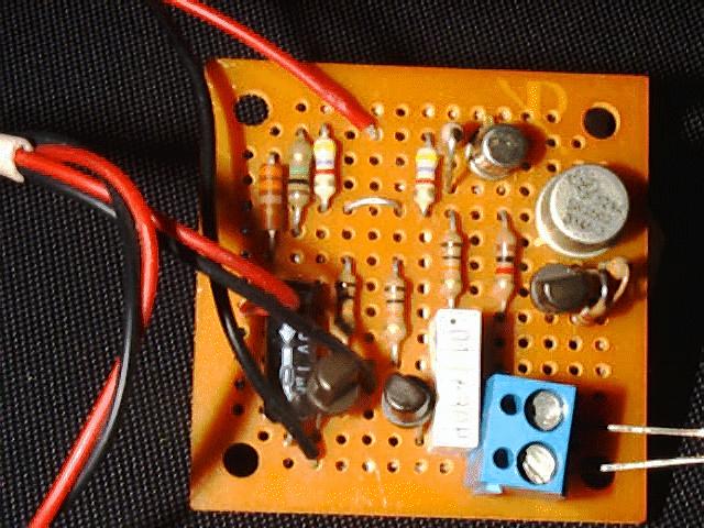
The basic flip-flop circuit is at left and middle of the picture.
The three transistors to the right are for buffering/inverting,
and for driving a relay. Q3 inverts Q2's output so that when Q2
is at cutoff, the current to Q4 is zero. Q4, in a TO-5 metal can,
drives the relay.
The LED's two leads can be seen at the lower right coming out of
the blue terminal strip. I added the third transistor, in the
black plastic case, to limit the current for the LED. The 39 ohm
resistor determines the LED current, with 30 ohms giving about 20
mA. When the voltage across this resistor gets to .6V, the Q5
transistor starts conducting and robs Q4 of its base current,
which limits the collector current also. The 470 ohm resistor
limits current and reduces the chance of oscillation.
The parts values can be changed somewhat to get lower current and
to optimize for the Vcc voltage. I think the 10k base bias
resistors could be increased to 22k or 47k to reduce current.
The JPG below is the picture of this circuit, built on a small perf board.
ASCII Schematic
+--------------------------------------------------+--------Vcc
| |
| |
\ 4.7 k \4.7k
/ /
\ \
/ /
| |
| 10K 10K |
+-----+----------/\/\/\---+ +------/\/\/\--------------+
| | | | |
| | Q1 | | Q2 |
| | NPN +---(----+ NPN |
| \ | 2N5172 | | 2N5172 | /
| \| | | |/
| |-----------+-------+ +---+-------------|
| /| | | |\
| / | | | | \
| | E | ----- E |
| | O | N.O. ----- |
| | |== | C2 |
| | O | P.B. | .01 uF |
| ----- | Sw ----- -----
| --- \ --- ---
| - / R2 - -
| \ 330
| /
| R1 1M |
+-----/\/\/\----+-----+
|
+ |
C1 -----
1 uF -----
|
|
-----
---
-
ASCII schematic of inverter/driver circuit
+-----------+----------------+---------------Vcc
| | |
2.2k \ | |
Adj / | |
for Vcc \ | Q3 |
from / E | PNP |
Q2 col- | | / 2N |
ector 10K | |/ 2907A |
>------/\/\/\----+-------| |
|\ |
| \ |
| |
| |
\ |
/ |
\ 1k |
/ | / Q4
| |/ NPN
+----+------------| 2N
| |\ 1613
| | \
Q5 \ | E |
NPN \| 470 |
2N |------/\/\/\-----+
5172 /| |
/ | \
| E /
| \ 39
| /
| |
+---------------------+------O
LED
+------O
|
-----
---
-
[Electronics Info Page] This page has been accessed  times since Sept 5, 1998.