 |
The Audio Pages |
| Elliott Sound Products | Project 83 |
MOSFET POWER
FOLLOWER
Pavel Macura
I have been trying for years to find high quality solution for power audio amplifier. I have tried valves (tubes), bipolars, mosfets, class B, AB, A push-pull, A single-ended ... you know what stuff I speak about.
Nelson Pass describes those terms perfectly (see www.passlabs.com). He also describes why he prefers the solution of single-ended class A MOSFET power stage with common Source (S-electrode). I think that his thoughts can be broadened even more. From my point of view a power MOSFET follower is a still better solution. It has benefits of single-ended class A amplifiers with common Source plus something more - less distortion, lower output impedance, higher input resistance and ... no feedback.
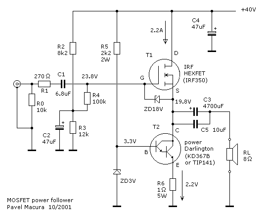
With one drawback - voltage gain is only +1 **, so it needs preamplifier able to deliver up to 12V RMS. The sound impression is perfect, surpassing the common Source MOSFET circuit. You can see schematic that I have tested in Fig.1.
** The actual voltage gain is in fact 0.98 (for RL=8 Ohm), as the IRF350 MOSFET transconductance is 6 [1/Ohm] and therefore ...
Gain = 6 / (6 + 1 / 8) = 0.979Measurement gave the same number.
The circuit consists of an N-Channel MOSFET voltage follower T1 (common Drain) and current source T2 (NPN Darlington). Current source is set to 2.2 Amps. With 40V of supply voltage the circuit is able to deliver about 17W into an 8 Ohm loudspeaker. The amplifier will take 88W from the power supply all the time.

Figure 1 - MOSFET Power
Follower
Bandwidth (-3dB) is from 4Hz to 250kHz. Rise time is 1.5 us. Output resistance 0.16 Ohm. The circuit is very tolerant of different kinds of load. Input resistance is 10 kOhm (R0), but can be increased up to 100 kOhm (R4) by omitting R0. Input capacitance remains relatively high, about 1500 pF. For this reason, the preamp should not have higher output impedance than 1 kOhm to maintain high frequency limit about 100 kHz. An input potentiometer can be used instead of R0.
The drawing shown is slightly different from Pavel's original. A fixed resistor has been used for the zener feed, and I made a couple of minor changes so the schematic was more like my standard style. [esp]If the value of the potentiometer is 5 kOhm then the high frequency limit will be about 70 kHz. The power follower can be connected directly to the output of CD player, and for reduction of volume potentiometer 5 kOhm can be used. As a preamplifier you may use Nelson Pass's projects "Bride of Zen" or "Balanced Line Stage" (see www.passlabs.com).
Note: The DoZ preamp will also drive this amplifier well, especially if the supply voltage is increased slightly. Although it is specified for +30V, it will operate quite happily at up to +40V. It may also be possible to direct couple the preamp's output to the power follower - omit R0, R2, R3, R4, C1 and C2 - as well as the output capacitor on the preamp. Needless to say, this would be my recommendation as the ideal preamp for Pavel's circuit - especially with direct coupling (see below). [esp]How does it sound? Wonderful, regardless low or high volume. Entire spectrum from bass to high is perfect. It only needs a good preamplifier.
I have tested an amp for a considerable amount of time and there was never problem with thermal runaway. Normally, the thermal coefficient of zener voltage of 3V type is negative, and so is Ube voltage of the darlington transistor. As Ube is reduced by -2mV/°C, zener voltage also goes down with increasing temperature inside a box (but the zener is not on the heat sink of the MOSFET and should not be). In fact there was a fluctuation of 40mA at 2A constant current, from my point of view it is negligible. Of course the heatsink for T1 and T2 should be better than 0.5°C/W for each transistor, so four such heatsinks are needed for stereo.
PROS:
KD367B's parameters:NPN Darlington
Ucbo <= 100V
Uceo <= 100V
Ic <= 8A
Ib <= 0.15A
Ptot <= 60W
hfe = 1000 approx.
Rthjc <= 2.1°C/W
fT = 7MHz
TO3 case
| Comments: | macura@centrum.cz |
| Original Page: | www.pha.inecnet.cz/macura/audiopage.html |
Pavel has PCBs available for this project, including the DoZ preamp section. If you are interested, please contact him directly at the above e-mail address.
To get the voltage gain needed for a normal installation, the DoZ preamp can be used. Everyone who has built this circuit has commented on the exceptional sound quality, and it is ideally suited to this application. Pavel has tried the combination, and he says ...
I have already checked the DoZ with the Follower. Both original versions, with caps (not direct coupled). The DoZ being supplied from external 30V power supply. The DoZ and the Follower interconnected by 5 kOhm potentiometer. Works perfectly, sounds wonderful.

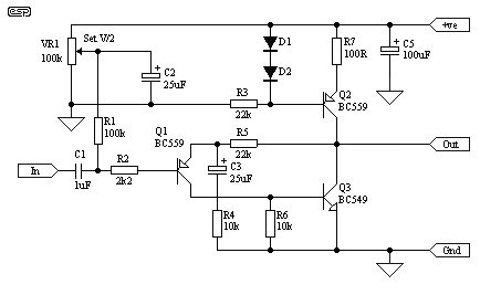
Figure 2 shows the modified version of the preamp, the output of which would be connected directly to R1 in Pavel's circuit. The quiescent output voltage is now set by VR1 in the preamp, and the voltage at the source of T1 should be set to 19.8V as shown in Figure 1 by means of VR1 - the voltage at the gate (preamp output) should be 4V higher, i.e. 23.8V. The DoZ preamp board is stereo, and can drive a pair of Pavel's power followers with ease. Q2 and Q3 should be fitted with small "flag" heatsinks to allow them to dissipate the increased power caused by the higher operating voltage.
As shown, the gain is 3.2, so it will require nearly 4V RMS input for full power. To change the gain, I suggest that R4 be changed to 3k3 to obtain a gain of 7.7 (17.7dB), which will give an input sensitivity of about 1.5V for maximum output. C3 will also need to be changed, and a value of 100uF will be more than adequate. I do not recommend that R4 be reduced to less than 2k7, which will give a gain of 9.15 (19.2dB). To maintain good low frequency response, C3 will need to be about 100uF, although even with 25uF, the low frequency response is maintained to 2Hz. Ideally, the input network should define the low frequency limit, so the higher value is recommended if R4 is reduced.
Unless a preamp is used in front of the amp, a pot will be needed at the input for gain control. 10k is fine here, and will not cause excessive loading on the source.
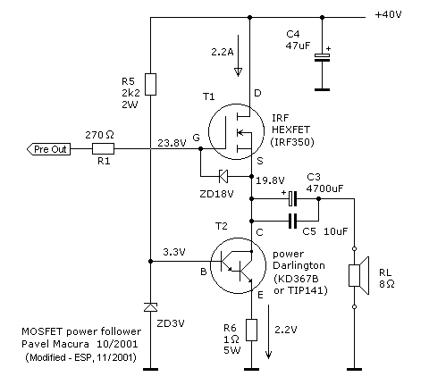
Figure 3 shows what Pavel's amplifier looks like after it is modified for direct coupling to the DoZ preamp. The complete circuit is deceptively simple, but should give a very good account of itself.

Figure 3 - Power Follower
Modified for Direct Coupling
The amplifier can also be used to drive headphones, and the quiescent current may be reduced considerably. R6 controls the current, and may be increased to 10 Ohms for use as a headphone amp. This will reduce the current to about 200mA and dramatically reduces the heatsinking requirements. 120 Ohm resistors should be used in series with the headphone output, and C3 can be reduced to 220uF for a single headphone output, or 470uF for dual outputs (using 2 x 120 ohm resistors).
| Copyright Notice. This article,
including but not limited to all text and diagrams, is the intellectual
property of Pavel Macura and Rod Elliott, and is Copyright |