Last modified: July 6, 2002
Other Projects:
Mosfet/Bipolar Power Follower
Balanced MOSFET Follower
INTRO
I have been trying for years to find high quality solution for power audio amplifier. I have tried tubes, bipolars, mosfets, class B, AB, A push-pull, A single-ended .... , you know what stuff I speak about.
Nelson Pass describes those terms perfectly (see www.passlabs.com). He also describes why he prefers the solution of single-ended class A MOSFET power stage with common Source (S-electrode). I think that his thoughts can be broadened even more. From my point of view a power MOSFET follower is a still better solution. It has benefits of single-ended class A amplifier with common Source plus something more - less distortion, lower output impedance, higher input resistance and .. no feedback. With one drawback - voltage gain is only +1, so it needs preamplifier able to deliver say 10Vrms. But sound impression is perfect, surpassing the common Source MOSFET circuit. You can see schematics that I have tested in Fig.1.
PROS:
The circuit consists of N-MOSFET voltage follower T1 (common Drain) and current source T2 (NPN Darlington). Current source is set to 2.2 Amps. With 40V of supply voltage the circuit is able to deliver about 17W into 8 Ohm loudspeaker. But takes 88W from power supply anytime. Bandwidth (-3dB) is from 4Hz to 250kHz. Rise time is 1.5 us. Output resistance 0.16 Ohm. The circuit is very tolerant to different kinds of load.
Input resistance is 10 kOhm (R0), but can be increased up to 100 kOhm (R4) when omitting R0. Input capacitance remains high, about 1500 pF. For this reason, the preamp should not have higher output impedance than 1 kOhm to maintain high frequency limit about 100 kHz.
An input potentiometer can be used instead of R0. If the value of the potentiometer is 5 kOhm then the high frequency limit will be about 70 kHz. The power follower can be connected directly to the output of CD player and for reduction of volume the potentiometer 5 kOhm can be used.
PARAMETERS
You can see the schematic of the power supply that I use in Fig.5.
PREAMPLIFIERS
As a preamplifier you may use Nelson Pass's projects "Bride of Zen" or "Balanced Line Stage" (see www.passlabs.com).
The other possibility is Rod Elliott's DoZ preamp (see www.sound.au.com or http://sound.westhost.com). An article describing the use of this MOSFET power follower with Rod's preamp can be seen at http://sound.westhost.com/project83.htm as "Project 83". The schematic of the DoZ preamp (©Rod Elliot, ESP, see his pages, and you can also order PCB's for the DoZ from him..) modified for this purpose can be seen in Fig.2.
To fulfill the specs of Q1-Q3 transistors, a supply voltage +Vs should be 30V. An experiment shows that they will survive supply voltage of 40V, so it is up to you to make a decision.... It might be better to use BC547/BC557 as they are rated at 45V.
When interconnecting the DoZ and the Follower, it is necessary to omit the R0 resistor of the follower. This slightly modified circuit can be seen in Fig.3. The complete amplifier is shown in Fig.4. As shown, the gain is 3.2, so it will require nearly 4V RMS input for full power. To increase the gain, change the R4 of the DoZ to 3k3 to obtain a gain of 7.7 (17.7 dB) and increase the value of C3 to 47uF.
DISTORTION
Distortion figure shows the harmonic distortion curve from 15 milliwats to 6 Watts at 1.8kHz and 8 Ohms for 7W version of the Follower with DoZ preamp. The distortion is mostly second harmonic.
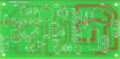
PRINTED CIRCUIT BOARDS
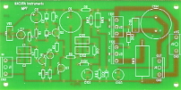
You can see printed circuit boards: the board and components layout. The preamp is included. Component numbers are a little bit different from the schematics, but one can easily identify them.
In case that you are interested to purchase the boards, please send me an e-mail
How does it sound? Wonderful, regardless of low or high volume. Entire spectrum from bass to high is perfect. It only needs a good preamplifier.
Comments: macura@centrum.cz
P.S. You may reduce the supply voltage or quiescent current if your heatsink is not good enough. 30V of supply voltage will give you about 10W/8 Ohm. R7 will be then used to trim a current through zener diode 3V to maintain appropriate quiescent current through R6. This current (the current of constant current source T2) can be easily measured - a voltage drop in Volts accross R6 resistor has the same value as the current through T2 in Amps, because of the R6 value (1 Ohm). In case you reduce quiescent current to 1.4 A (at 40V of supply voltage) you will get about 8W/8 Ohm.
Pavel Macura November 9, 2001
PHOTOS
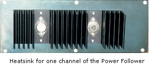
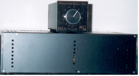
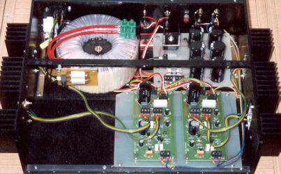
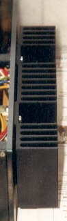
Following photos show construction of the amplifier. Please note that the heatsink shown is suitable for continuous operation with total power dissipation of 60W (per one channel). For power dissipation of 88W the heatsink should have twice that size.
heatsink
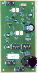
PCB with components
power follower + D7A volume control
box
side
OTHER SCHEMATICS
Sinclair Z-30 (modified, revised April 12, 2002) : class
A-B amplifier from early seventies
Transiwatt TW 40
Last modified: July 6, 2002