Module 6-3
PHOTOGRAPHIC RECORDING MEDIUMS
©
Copyright 1987 by The Center for Occupational Research and DevelopmentAll rights reserved. No part of this book may be reproduced in any form or by any means without permission in writing from the publisher.
The Center for Occupational Research and Development
601 C Lake Air Drive
Waco, Texas 76710
Printed in the U.S.A.
ISBN 1-55502-024-0
(1) Many experimental phenomena must be permanently recorded for future analysis and documentation purposes. When either high speed and/or high resolution is desired, such recordings frequently make use of photographic techniques. The field of photographic science is so broad that it won’t be feasible to cover the many facets of this interesting technology. We’ll concentrate on the basic principles involved, and address important photographic material characteristics that must be considered for the optimum selection from a large range of candidate recording mediums.
(2) This module will cover the basic concepts and techniques of the black and white photographic process with a brief introduction to color photography. We’ll discuss properties of photosensitive materials such as sheet, roll, and plate film, as well as Polaroid emulsions.
(3) Details of film processing procedures—from chemical changes that take place during exposure, through developing, washing, fixing, and various other photographic processing techniques—will be presented. You’ll learn about sensitometry as a way to determine film performance and suitability, and work a lab experiment on sensitometry. You should know standard precautions for dealing with high-quality optics and hazardous chemicals. You should be aware of the principles and procedures of introduction to laser safety, helium-neon gas lasers, F-stops and apertures, laser power and energy measurements, the cleaning of optical components, sources and their characteristics, and radiometry and photometry.

(4) When you complete this module, you should be able to do the following.
1. Describe in your own words the process of latent image formation in photographic emulsions.
2. Assume an appropriate exposure has been made. Describe in functional detail the necessary processing steps to arrive at a black and white negative. The steps to be described will include development, stop bath, fixing, washing, and drying.
3. Sketch a typical H-and-D curve that defines the ordinates and identifies the following regions on the H-and-D curve:
a. Inertia point
b. Background fog level
c. Gamma (g )
d. Saturation
e. Latitude
f. Speed
g. Overexposure (reversal, solarization)
h. Region of normal exposure
i. Toe
j. Shoulder
4. Define reciprocity and reciprocity failure as regards film behavior.
5. Exhibit—by means of a graph—the spectral sensitivity of a typical photographic emulsion. Describe its importance in the concept of spectral matching.
6. Through the use of given technical characteristics, select an appropriate emulsion for a given application to include spectral sensitivity, speed, and resolution.
7. Given a reproducible light source and appropriate photographic materials, cameras and chemicals, expose and develop a photographic emulsion to determine a relative H-and-D curve for the emulsion under a given set of conditions.
DISCUSSION
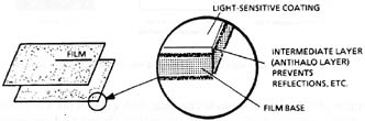
(5) Photographic images produced by various photosensitive emulsions are dependent on the formation of a latent silver halide (silver bromide, silver chloride, etc) image through photochemical reaction. This latent silver halide image can be reduced to a permanent image consisting of metallic silver through a process known as developing, whereupon the unexposed silver halides are removed by a solvent known as a fixing agent. Suspended particles of elemental silver remain behind in the emulsion. They reproduce the intensity distribution that was incident upon the film during the time of exposure. Figure 1 shows a typical film.
Fig. 1
Cross section of a typical black and white photographic film
(6) The final result of this process is called a negative. That’s because the areas of greatest intensity in the photographed scene seem black, and the areas that are dim appear as clear (transparent) areas when viewed with back illumination. Of course, this negative can be inverted to produce a positive through an additional photographic cycle. This photographic process is shown in Figure 2. The above description briefly describes the process of image formation.
(7) Let’s look at a more detailed description of specific aspects of the process. Photographic film generally consists of a thin material or film base made of glass, cellulose acetate, nitrocellulose or other organic compounds. Frequently, film bases made of polyolefins and polyearbonate are used for scientific purposes because of their greater strength and dimensional stability. A light-sensitive emulsion is applied to this base.
(8) Frequently, there’s a thin, dark-color intermediate layer called the antihalo layer. It acts as an absorber for scattered radiation. The antihalo layer also decreases reflection from the film base. Reflection might lead to unwanted additional activation of silver halide particles. A typical emulsion may consist of 40% silver bromide crystals, 50% gelatin (as a binder), and 10% water. We’ll see later that the size of the active silver halide crystals determines two important characteristics of photographic emulsions. These characteristics are speed and the resolving power.
(9) The silver bromide emulsion normally used in many black and white films isn’t equally sensitive to all frequencies of light. However, you can change the sensitivity dramatically by adding small quantities of additives such as gold, mercury, etc. By the use of other photosensitive materials, the spectral utility of films can be extended from the infrared down through the visible, to the ultraviolet, and into the X-ray region.

Fig. 2
The basic steps in the black and white photographic process
(10) So, it’s important to be able to select—from the numerous photographic emulsions available—that particular one that’s best for recording the technical data you need in an experiment. You must therefore be familiar with the properties of photographic emulsions that will allow this optimum selection.
(11) The best way to determine a photographic emulsion’s technical characteristics is by sensitometry. Sensitometry is the science of evaluating the response of photographic materials after exposure and development under controlled and specified conditions. Sensitometric properties are closely related to the way the film was manufactured, exposed, processed, and so on. Factors that affect the darkening or exposure of photographic emulsions are the spectral content of the exposing radiation, the type and degree of development, the procedures used to measure the resultant density, etc. All are related through sensitometry. They will accurately describe the density or darkening obtained under a given set of conditions.
(12) Let’s define some useful terms. The first and most important is exposure H which is formally defined in sensitometry as the product of the irradiance E on the film and the time (D t) for which the film is exposed to this irradiance.
H = E (D t) |
Equation 1 |
(13) Recall that optical density (D) of a material was defined as the negative log of the transmission.
D = –log T |
Equation 2 |
(14) Density is defined logarithmically since the response of the eye is logarithmic and film normally is evaluated by human observance. This is analogous to the decibel (dB) scale used to measure relative sound levels.
(15) So, a density of 1 corresponds to a transmission of 10%. A transmission of 0.1% would correspond to an optical density of 3.
The Characteristic Curve
(16) The characteristic curve normally is used to describe the sensitometric properties of main interest to technical photographers. This curve in reality plots the photographic effect as output versus input, that is, the density produced in an emulsion as a function of the exposure. Most frequently this curve is plotted as density versus the log of the exposure. So it’s frequently known as the D, log H curve or the H-and-D curve, after Hurter and Driffield. Hurter and Driffield proposed that the log of 1/T (density) should be proportional to the mass of silver per unit area in the developed layer. Their experiment consisted of exposing photographic plates to a light of constant intensity and varying the time of exposure D t. The result leads to a curve shown in Figure 3.
(17) The H-and-D curve is probably the most simple and most-used way to describe the performance of a given photographic emulsion. This curve will be unique for each film, developing process, and exposure conditions such as spectral characteristics of the exposing source. Let’s examine this curve in detail.
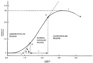
Fig. 3
Typical H-and-D curve
(18) The first characteristic of the curve is the toe or inflection region
(19) The density level f corresponds to the density of a developed photographic emulsion that hasn’t been exposed to light. This is often called the background fog density. This density level can change depending upon specific processing procedures used. The extrapolation of the linear portion
(20) For most applications, the linear portion
g = tan q |
Equation 3 |
A high-contrast film has a high gamma.
(21) The exposure range between g and h is called the latitude. Again, it’s the part of the curve that’s most suitable for recording photographic scenes that will yield the most satisfactory reproduction of various shades or tones.
(22) It’s obvious that under conditions of heavy exposure there will be fewer and fewer silver halide molecules left to be reduced to elemental silver. So a saturation takes place under these conditions. The onset of this process takes place at point h. It continues through the shoulder region to point j. The density at j is denoted dmax or ds and is called the maximum or saturation density with additional exposure. This process is called solarization or reversal, since a greater exposure reduces the final density. The detailed reasons for this response are discussed in books and journal articles on photochemistry.
(23) It’s important to remember that a given H-and-D curve isn’t only characteristic of the film, but can be modified through processing changes and changes in the spectral content of the exposing source. H-and-D curves for all commercially available films, together with the recommended processing criteria, are readily available in handbooks or pamphlets from various film manufacturers.
Sensitometry
(24) Frequently you want to find the H-and-D curve for your particular experimental arrangement and processing procedures. Generally, you can get these experimentally with a densitometer. A sensitometer is an instrument that produces, on a photographic material, a series of precisely known graduated exposures. The correct performance of a sensitometric measurement depends on five determinable conditions. The conditions are:
1. a light source that emits radiation of known intensity and spectral composition,
2. a means of producing graded exposures of known relative values,
3. standardized development conditions,
4. a way to quantitatively measure the developed image,
5. a way to interpret the results by suitable quantities or expressions.
(25) The essential components of a sensitometer are shown in Figure 4.
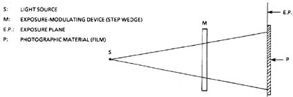
Fig. 4
Essential components of a sensitometer
(26) This simple arrangement makes use of a step wedge. A step wedge is usually a film that has known density gradations. The density gradations are usually sufficiently small. But, because of their large number (>20), they can vary the recorded density from a single exposure to cover the whole H-and-D response curve. Of course, each portion of the wedge must be illuminated under uniform conditions (intensity, etc.). Numerous types of sensitometers are used in the photographic field.
(27) The various sensitometers can be designed to address specific measurements in the sensitometry field such as the very-short-duration response of emulsions, the response of photographic materials to repetitive exposures, multicolored sensitometers for color photography, and so on. We’ll do a very simple sensitometry experiment in the lab for this module.
Reciprocity and Reciprocity Failure
(28) Equation 1 indicates that, for a given exposure H, intensity and exposure time vary inversely. In other words, if one increases, the other must be decreased a corresponding amount to produce the same film density. This is reciprocity. It means that a source of unit intensity exposing a film for a given duration produces an image density the same as if the film were exposed by a source twice as bright for only half the duration as the original source.
(29) However, if you investigate this reciprocity at the extremes of exposure, you’ll find that the relation fails. For example, a Q-switched laser with a pulse length of 10 nsec illuminating a photographic emulsion at 106 W/cm2 corresponds to an exposure of 10–2 joules/cm2. Reciprocity states that a source that illuminates the film at a level of 1 milliwatt/cm2 for 10 seconds—which can be produced by a CW gas laser—is also an exposure of 10–2 joules/cm2. You’d expect the density to be the same from these two exposures. However, this won’t be the case. This is not a failure of the film, but rather a characteristic of it.
(30) This reciprocity failure comes about because we’ve assumed that the photochemical action is dependent only on the amount of light energy absorbed and not on the rate of absorption (power). For this reason, in many high-speed, time-resolved photoinstrumentation observations, you have to determine the H-and-D curve as a function of the temporal characteristics of the exposure. You can’t rely on commercial curves that primarily govern the normal reciprocal response of photographic emulsions.
Spectral Sensitivity
(31) Spectral sensitivity is another important characteristic of photographic emulsions. It’s of particular concern to the scientist. The spectral sensitivity describes the degree of photographic response to radiation of various wavelengths.
(32) Technically, sensitivity is the reciprocal of exposure required to produce a specified density above background fog when the material is processed as recommended. Normally, two graphical methods are used to describe spectral sensitivity—the sensitivity of an emulsion as a function of wavelength. The first, frequently used when dealing with a monochromatic source such as a laser, is the evaluation of an H-and-D curve at a specific wavelength. However—more generally as an aid in selection of emulsions—plots such as in Figure 5 often are used.
(33) A summary of Kodak photographic emulsions frequently used in scientific photography is shown in Figure 6. As you can see, type Z emulsions are used often to photograph lasers operating at 1.06 m m. A variety of emulsions are suitable at the 0.6328-m m wavelength of the helium-neon laser.
(34) The way that emulsions vary in spectral sensitivity comes from a process known as sensitization. Sensitization generally is changing or altering the spectral sensitivity by adding certain dyes to the emulsion. The variety of dyes used is very numerous. We won’t cover them here. However, film manufacturers offer spectral sensitivity data on all photographic materials sold.
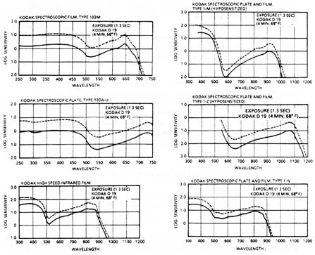
Fig. 5
Spectral sensitivity of selected Kodak scientific films
(35) Another aspect of sensitization can be achieved in a similar way. That’s the increase of a film’s speed from its normal sensitivity or speed. Most sensitizations that increase a film speed come from changes in the processing procedure—either by the addition of heat or by chemical treatment of the film emulsion before exposure.
(36) Hypersensitization is a frequently used process to increase the infrared sensitivity of films suitable for use in that portion of the spectrum. Here the emulsions are immersed in a caustic such as sodium hydroxide or ammonia immediately before exposure. This process greatly increases the response of the emulsion. But it must be done carefully to ensure a uniform increase in sensitivity over the entire film area.
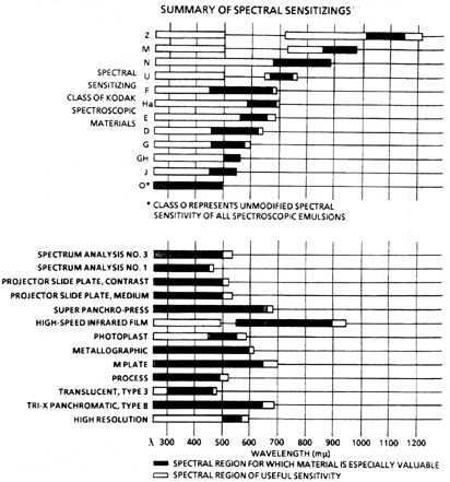
Fig. 6
Summary of spectral sensitizing for Kodak scientific and technical emulsions
Resolution
(37) A final characteristic of photographic emulsions that frequently must be specified is resolution. Resolution or resolving power is the ability of emulsions to record fine details. To find the resolution of an emulsion or complete photographic system, you use a bar chart that’s photographed at a greatly reduced scale. This aspect will be covered in later modules.
(38) Suffice it to say, upon examination under a microscope, you can use the number of dark lines per millimeter that are just recognizable in the image as an indication of resolving power.
(39) The resolution of an emulsion depends only slightly on development. But there are great variations at both high and low exposure levels. The maximum resolution usually occurs at some intermediate exposure.
(40) Resolving power is determined in large part by the physical construction of the film. (See Figure 7.) Film resolution can be altered (deteriorated) by the various coatings of the hi lm base. These coatings are essentially optical components that can cause deviation of light rays—generally from scattering. Low-resolving-power materials have resolutions below 56 lines per millimeter. Emulsions—for example, those used in holographic applications—have been produced with extremely high resolving power of greater than 2,000 lines per millimeter.
ANTIABRASION COATING |
SILVER HALIDE BEARING GELATIN EMULSION |
FILM BASE |
ANTI-HALATION (AND NONCURLING) GELATIN COATING |
Fig. 7
Schematic view of film construction
(41) Some specialized emulsions have been developed that are essentially "grainless." One example is the so-called "DCG" or dichromated gelatin holographic plate. It’s often used with argon lasers to produce bright "whitelight" reflection holograms. These plates function on a principle that’s entirely different from conventional silver halide film.
(42) In the DCG plate, intense green light from the argon laser is absorbed by ammonium dichromate dissolved in the gelatin. The absorption of the light, coupled with a dehydration process, causes a change in the index of refraction of the emulsion. Therefore, the holographic image is stored as phase information in the plate, rather than areas of high and low transmission as is the case in traditional photography. In the DCG plate, the limit of resolution is down near the molecular scale rather than being dependent on grain size. Holography is discussed in greater detail in Course 7.
(43) The ultimate practical limit to the resolution is the grain size of the photosensitive material in the emulsion. Generally speaking, emulsions used for high-speed films have very thick emulsions that lead to large grain sizes. The grain is actually a group of reduced silver atoms to form a detectable area. For thinner emulsions, you generally have smaller grain sizes, thus higher resolving power and reduced speed. (See Figure 1.)
(44) The specific technical objectives will dictate the required characteristics. For example, in electron microscopy or optical microscopy at high magnification, you use a long exposure with a low-speed, high-resolution film. Dim transient events will need a high-speed film for recording, even though the resolution may suffer. We’ll see in later modules how we can use other techniques—such as electronic image intensification—to compensate for some of the undesirable features of photographic emulsions.
Film Processing
(45) Let’s talk about—in some detail—the development process often used with black and white emulsions. (Refer to Figure 2.)
(46) The first step in the process is called development. Development is achieved by chemical treatment of the emulsion to produce an observable darkening of the film corresponding to the object being reproduced or imaged. As we’ve said, this darkening comes from the reduction of activated silver halide photosensitive materials to pure elemental silver. The chemicals used in this process are called developing agents. A mixture of these chemicals in water is called the developer.
(47) Most commonly used developer solutions include metol and hydroquinone. Specific developers are recommended for each type of emulsion. This information is readily available through many sources. You can find it in the Photo Lab Index and scientific and technical data available from specific film manufacturers.
(48) The length of film immersion in the developer is a critical factor in the development process. If you leave the emulsion in the developer too long, too many silver halides—even those not activated—would be reduced to pure silver. On the other hand, the development process isn’t immediate. So a rapid immersion would reproduce an essentially undiscernable darkening. At the end of the right development time, the "negative" is fully developed. As we’ve indicated, it’s a reversed representation of the photographed subject.
(49) Another important variable is the development temperature. The development process is a chemical reaction, so you can expect elevated temperatures to speed up the reaction. If the temperature is too cold, no reaction at all may take place. For normal processing, the preferred temperature is usually around 68ḞF. Many developing procedures, such as immersion times, are specified assuming the solutions are at 68ḞF.
(50) When the emulsion has been developed according to proper procedure, the film still contains all the silver. It has both the reduced silver and the silver that’s still combined in the halide form. To remove the unreacted silver halides, you must perform chemical reaction on the emulsion.
(51) Before this next step, you should wash the emulsion with pure water to (1) stop the development process and (2) avoid contamination of the chemicals used in the next step by the developer chemicals. This is frequently called a stop bath. It’s usually made weakly acidic to neutralize the alkaline developer. Acetic acid is the most commonly used chemical. This reaction actually dissolves the unexposed silver halides.
(52) The next chemical step is fixing. The chemical commonly used is called hype. Hypo dissolves the unexposed silver halide. This process is also selective. The hypo dissolves the silver halide, but not the reduced silver. Again if this process is too long, the hype eventually will dissolve even the reduced silver. So this step is also critical in length of time and temperature that the emulsion is in contact with the fixing bath.
(53) Fixers also contain chemicals that help to preserve the film by hardening the gelatin. Sodium sulphide is the chemical commonly used for this purpose.
(54) At the end of the fixing process, the emulsion is washed in pure water to remove all traces of chemicals. Then it’s carefully dried under controlled conditions. The total development process is summarized in Figure 8.
(55) We’ve just discussed those aspects commonly found in routine development. But, many variations can be used to modify the sequence of steps. We won’t delve into the variations to any extent.
(56) It’s important to realize that modifications to the sequence can make photographic emulsions more able to record luminous events. One such modification is the forced development of films.
(57) Forcing can greatly increase the normal speed of typical emulsion. For example, Royal-X Pan film has a rating of ASA 1250. It can be "pushed" to an equivalent ASA speed of approximately 1600 by changes in the development process. You’d immerse it in the developer longer, with the developer at a much higher temperature. This change from normal processing gives a higher-contrast film. You’d get degraded resolution, however, due to the very grainy structure of the final developed film emulsion.
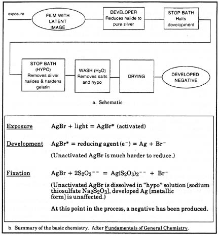
Fig. 8
The photographic development process
Printing
(58) If you put a negative in close contact with another piece of unexposed and undeveloped sensitive material, the new material may be exposed by passing light through the negative under controlled conditions.
(59) Each grain of silver will cast its shadow on the new material, and inhibit exposure of the silver halides at that point. Where the negative is clear, light will pass to expose the new material. Where the negative is dense and black, little or no light passes to the new material. The new material then is a negative exposure of the original negative. The final result, after development, is an accurate reproduction of the originally photographed object. The new negative is called the positive. The second sensitive material used determines the form of the positive. If the material is photographic paper, the positive is a print. When the positive is produced on a film, it’s called a transparency. The transparency can be projected, like motion-picture film. From one negative, you can make many prints or transparencies.
(60) For amateur, and some scientific work, such as oscilloscope recordings, a single print may be all that you need. In this case, you can eliminate the film negative through a special process called reversal process. Here, the originally exposed film contains the finished positive. The process differs in the steps that follow development.
(61) Remember that after development, the negative silver image and all the unexposed silver halides are in the emulsion. You can bleach this silver image (make it soluble) with a selective chemical reaction that affects only the silver. It doesn’t affect the undeveloped silver salts. Now the emulsion consists of soluble silver in the negative image and the silver halide left over from the development process.
(62) A clearing bath removes the pure silver and leaves only the unexposed silver halides in the emulsion. A deliberate second exposure of the halides will render them reducible by any development that transforms all silver halides to pure silver.
(63) The new image is precisely the opposite to the negative that would have been produced by normal processing. It’s a positive. This reversal or "direct positive" system is used in some automatic cameras that use sensitized paper and produce a print directly (Polaroid film camera systems).
Color Photography
(64) You’ll often need to use color photography to maximize the information recorded in technical photography. There are many different processes of color photography, but generally they can be divided in two main groups:
• Additive processes used primarily for transparencies.
• Subtractive processes used for both transparencies and paper prints.
(65) In all cases, the principles of color photography are essentially the same in that images are formed in three primary colors. Color film has three separate emulsions. One emulsion is sensitive to the yellow, one to the green, and the last to the red portion of the spectrum. This is done by using dyes that are sensitive to these portions of the spectra.
(66) The principles in which these single-color images are combined to produce the final "essentially" continuous spectrum result varies from one type of process to another.
(67) One method is the reversal process. It’s a subtractive process, and it’s the one most commonly used today. Because color photography development normally is done by a special processing laboratory, we won’t go into these details.
(68) A particular type of multiple-emulsion film—called extended-range film—is used often in scientific photography. If you’re investigating a source that has dim as well as bright regions of emission, you can’t record many important aspects of the event under study on normal film. That’s because of their unlimited latitude. With extended-range emulsion, you can use three different layers. The layers correspond to three separate colors, and each has a different sensitivity. Events that have been investigated with this type of film include high-altitude nuclear detonations, exploding wires, laser produced plasmas, and so on. Some of these films have a latitude of response over six orders of magnitude in exposure.
(69) To evaluate and analyze the documented event, you simply put a filter in front of the projector. The filter is one that selects from the stack the individual emulsion whose sensitivity corresponds to the level of illumination of interest. Again, this film normally is processed under special development conditions not normally used with limited darkroom capabilities.
Polaroid Emulsions
(70) Because of the popularity and frequent use of Polaroid photography in technical work, let’s describe the characteristics of these emulsions. To help you to understand both Polaroid films and color photography, we’ll address specifically the Polaroid Land color film process.
(71) Processing of ordinary color films takes many complex operations. So the rapid one-step production of colored positives by Polaroid colored film is used a lot in photography. This large use is in no small measure due to the fact that you can reproduce a colored positive within one minute of the exposure.
(72) Figure 9 shows Polaroid color film. It’s coated with three photosensitive layers that have the silver halide crystals, three layers that have dyes and developers, and two intermediate layers. Each pair of silver halide and spectrally selective dye layers responds to the blue, green, and red regions of the spectrum.
(73) As shown in Figure 9, blue light is primarily stopped in the first layer, green will be stopped in the second silver halide layer, and red will pass through to the third silver halide layer. Obviously, light sources that have all three colors will cause an exposure in each silver halide layer as shown.
(74) After exposure, the film or a strip is pulled from the camera. This releases the developer-activating paste. Through the action of smooth precision-spaced steel rollers, the negative layer is pressed firmly onto the so-called positive layer. The positive layer has the color and intermediate layers and an acid layer for neutralization and stabilization of the color image.
(75) Paste rapidly diffuses into the negative. It first enters the blue-sensitive layer and liberates a yellow dye in the adjacent layer. It then diffuses by similar process through the other pairs of layers. In the green-sensitive pair, it liberates a purple dye, and in the red-sensitive layer, a blue-green dye is liberated.
(76) The dyed molecules that have been liberated by the paste are a reproduction of the latent image. They now diffuse in all directions. When they encounter a grain of reduced silver they’re retained and held by it. The dye molecules that don’t encounter silver grains keep migrating until they reach the positive layer. They’re retained there.
(77) At the end of the process, water is formed in an alkali neutralizing process. It serves to wash the positive.
(78) This explanation didn’t just describe the way Polaroid prints are obtained. It also told you how one-step rapid processing emulsions can lead to positive prints that faithfully reproduce the color tones in the photographed scene.
(79) Between the extremes of the Polaroid Land process and the one originally described for black and white film negatives, there are a lot of slight variations in photographic development processes. If you’re interested in more detail, you should look at the references cited at the end of this module.
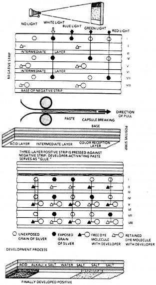
Fig. 9
Polaroid Land color film
Spectral Matching
(80) Spectral Matching is an important concept in technical photography. To get the best performance inherent in the photographic process, you choose the specific photographic emulsion for optimal response in recording the event under study.
(81) For example, Polaroid emulsions often are used to record oscilloscope traces. To get the maximum resolution and performance of the oscilloscope-recording process, you need to use as small a spot as is detectable on the oscilloscope face.
(82) As you know, the oscilloscope face is coated with a phosphor that fluoresces from impact of the electron beam that’s translated across the face plate as a result of the various sweep circuits. There’s a wide selection of phosphors available on oscilloscopes. They have different emission characteristics.
(83) To get the maximum resolution in the recording process, you should use an emulsion of the required resolution. It should be one that’s maximized in spectral sensitivity at the peak of the wavelength emitted by the fluorescent screen. For example, you’d use a blue-sensitive film when you record images on an oscilloscope with a P-11 phosphor that emits primarily in the blue.
(84) From the technical data in this module, you should see that there’s limited infrared response of normal photographic emulsions. So, when you record weak emissions from 1.06-m m-operating neodymium YAG lasers, you’ll often use type-1Z plates that have the greatest response in the region (See Figure 6.)
(85) You can see that, to select the best photographic emulsion for recording any technical event, you don’t just consider the characteristics of the film. You also try to match the film to the emission characteristics of the object to be recorded.
Characteristics of Photosensitive Materials
(86) To help you evaluate the suitability selection of photographic emulsions for specific technical applications, you should get information that’s readily available from film manufacturers. You can find an excellent compilation of commercially available films and plates normally used within the United States for various scientific and industrial photography. It’s Kodak Booklet No. 9. The title is "Kodak Plates and Films for Science and Industry." An example is shown in Figure 10, which is shown on two pages as Figures 10a and Figure 10b.
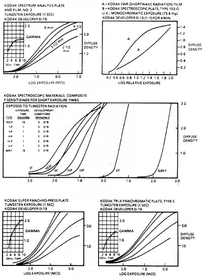
Fig. 10a
Some typical Kodak Film characteristics
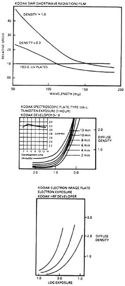
Fig. 10b
Some typical Kodak Film characteristics
(87) You can find similar information for other films made within the United States, such as DuPont X-ray films, or from film manufacturers in other countries, such as Ilford in England, Agfa-Gevaert in West Germany, Fuji in Japan. In many cases films made in other countries have unique characteristics that make them suitable for specific applications such as high-resolution holographic recording.
(88) Characteristics of available Polaroid films are given in Table 1. The spectral response and density curves for the seven more commonly used Polaroid films are shown in Figure 11. This information has been taken from the Photo Lab Index.
Table 1: Speed of Polaroid Films*
Film |
|
Picture |
Picture |
Speed |
Devel Time |
Roll Films
20 |
8-exp roll |
B & W print |
2Ẅ Ṫ 3ỳ |
3000 |
15 sec |
32 |
8-exp roll |
B & W print |
2Ẅ Ṫ 3ỳ |
400 |
15 sec |
38 |
6-exp roll |
Color print |
2Ẅ Ṫ 3ỳ |
75 |
60 sec |
42 |
8-exp roll |
B & W print |
3ỳ Ṫ 4ỳ |
200 |
15 sec |
48 |
6-exp roll |
Color print |
3ỳ Ṫ 4ỳ |
75 |
60 sec |
Pack Films
107 |
8-exp pack |
B & W print |
3ỳ Ṫ 4ỳ |
3000 |
15 sec |
108 |
8-exp pack |
Color |
3ỳ Ṫ 4ỳ |
75 |
60 sec |
4 Ṁ 5 Film Packets
51 |
20 single-exp packets |
High-contrast B & W print |
1 Ṫ 5 |
200 |
15 sec |
52 |
20 single-exp packets |
B & W print |
4 Ṫ 5 |
400 |
15 sec |
57 |
20 single-exp packets |
B & W print |
4 Ṫ 5 |
3000 |
15 sec |
58 |
10 single- |
Color print |
4 Ṫ 5 |
75 |
60 sec |
55 P/N |
20 single-exp packets |
B & W and |
4 Ṫ 5 |
50 |
20 sec |
Special- purpose Films
46-L |
8-exp roll |
Cont-tone B & W |
3ỳ Ṫ 4 |
800 |
2 min |
146-L |
8-exp roll |
High-contrast |
3ỳ Ṫ 4 |
200 |
15 sec |
410 |
8-exp roll |
High-contrast |
3ỳ Ṫ 4ỳ |
10,000 |
15 sec** |
* Processing times on this table may need some modification dependent or the temperature conditions. You can find more detailed information on the instruction sheet packed with each particular type of film.
** To facilitate rapid-sequence recording, Type 410 Land film can be advanced at 2-second intervals and prints developed 13 seconds outside the camera.

Fig. 11
Spectral response and density curves for Polaroid films

1. Describe in your own words the process of latent image formation in photographic emulsions.
2. List the required steps, and name the various bath solutions and times required for processing the film used in the laboratory (in proper sequence).
3. What are the two variables plotted on an H-D curve?
4. Draw a typical H-D curve and identify the following:
a. Toe
b. Shoulder
c. Latitude
d. Inertia point
e. Solarization region
f. Contrast
g. Background fog level
h. g
i. Saturation
j. Speed
5. Define reciprocity and reciprocity failure as regards film behavior. Convey the same meaning as given in the text. Use examples.
6. Draw a graph of the spectral sensitivity of a typical photographic emulsion similar to the graphs given in the text. Relate the importance of this graph to the concept of spectral matching.
7. A technical photographer wants to photographically record a weak 1.06-micrometer laser radiation pattern in a holographic investigation. What two prime characteristics should she look for in selecting an emulsion? Check the most appropriate emulsion from the technical information given in the text.
8. If, after initial experiments, she determines that the chosen emulsion doesn’t have enough sensitivity, what alternatives does she have for overcoming this deficiency?
For the next two problems, you’ll need a copy of the Kodak B & W Darkroom Dataguide.
9. You are about to develop Kodak Tri-X Pan film using Polydol developer in a darkroom that’s at a temperature of 24.5ḞC. Assume that you will develop the film "normally" (no "push"). How long should you keep the film in the developer?
10. Repeat the above problem. But now consider that you’ll be "pushing" the film. (Push processing compensates for underexposure, but at the expense of increased graininess.)

Roll of twenty-exposure black and white film (Kodak Tri-X Pan)
Camera (35 mm) with bulb ("B") or time ("T") shutter settings available
Electronic flash unit that can be single-flash triggered (Strobotac)
Darkroom facility and chemicals for black and white processing
Optical bench with fixtures (holders)
Graph paper
Kodak Black and White Darkroom Dataguide
HeNe Laser (about 2 mW)
Collimator/beam expander
Iris
Optical power meter

1. Set up on a 1-meter optical bench, the large frosted glass plate and camera, so that the camera is focused on the glass plate and the plate covers the field of view. See Figure 12.
2. Set up the Strobotac behind the glass plate (approximately 120 cm) so that illumination on the plate will be fairly uniform. Place an ND 3.0 filter in front of the lamp to attenuate the bright flash (ND value will depend on brightness of strobe).
3. Set the Strobotac setting for single-flash operation.
Caution: If you decide to use the "auto-fire" mode of your flash for the longer exposures (128, 256, etc), make sure that the flash intensity is the same in the single-shot and auto modes. The old-style General Radio strobes decreased flash intensity significantly in the "auto-fire" mode.
4. Set the camera on time ("T") setting, after advancing the film to the first frame. Then set the camera aperture to the smallest setting: f/22 or f/16.
Note: Some cameras do not have "T" setting. So you must use the bulb ("B") setting. On "T" one click opens the shutter and another closes it (two clicks per picture required).
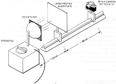
Fig. 12
Exposure setup for production of H-D curve
On "B" the shutter stays open as long as the shutter button is depressed. It closes when you release the button. In this case, you should use a shutter extension cable.
5. Darken the laboratory, open the shutter and flash a single flash. Then close the shutter and advance the film.
6. Repeat Step 5, but flash the unit two times.
7. Repeat Step 5, but flash the unit four times.
8. Repeat Step 5, doubling the number of flashes for each succeeding frame.
9. After you’ve made about 9 exposures, remove the film from the camera.
10. Develop the film according to manufacturer’s instructions (see Appendix A). Cut film into 35-mm slides and mount in cardboard or plastic slide holders. Number the slides by order of exposure.
11. Note visually the variation in the film density as a function of the number of flashes. If all of the exposures look approximately the same density you’ll have to repeat the experiment. Change either the value of the ND filter or the F# on the camera lens to either increase or decrease the exposure until you get a good "dynamic range" of exposures.
12. Set up an optical arrangement as shown in Figure 13.
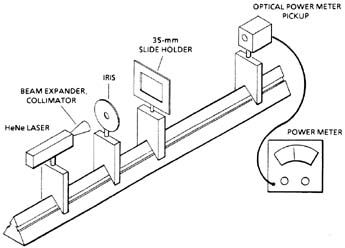
Fig. 13
Setup for making relative H-D curve
13. Adjust the collimator so that the beam is about 1 cm in diameter. Set iris to about 1/2 the collimated beam diameter so that only the center of the beam is used. Align the beam with the center of the exposed region on the film.
14. Measure the power, with meter, for each exposure made. Tabulate "number of flashes." Plot the data obtained in this step with density (103 1/T) on the Y-axis and log to the base 2 of the number of flashes on the X-axis. Use the following conversion table:
No. flashes |
Log 2 (No. flashes) |
|
0 |
— |
|
1 |
0 |
|
2 |
1 |
|
4 |
2 |
|
8 |
3 |
|
16 |
4 |
|
32 |
5 |
|
64 |
6 |
|
128 |
7 |
|
256 |
8 |
|
512 |
9 |
15. Plot density (log 1/T) versus log2 (# of shots) on graph paper. On your graph show the linear portion of the H-and-D curve, saturation (if you achieved it), the film’s gamma and the film’s inertia. Note that your values for gamma and inertia are only "relative" values because the horizontal axis of the graph isn’t given in actual exposure units (joules orergs per cm2).

Number of |
log2 (Number |
Power Reading |
Power Reading ẁ
|
0 |
|||
1 |
|||
2 |
|||
4 |
|||
8 |
|||
16 |
|||
32 |
|||
64 |
|||
128 |
|||
256 |
|||
512 |
P0 = incident power = ________mW transmission T

Baines, H. The Science of Photography. New York: John Wiley & Sons, Inc.
Brode, Wallace R. Chemical Spectroscopy. New York: John Wiley & Sons, Inc., London: Chapman and Hall, Limited.
Eastman Kodak Co., Rochester, NY.
Basic Developing, Printing, Enlarging, No. J-2.
Kodak Black-and-White Darkroom Dataguide, No. R-20.
Kodak Films for CATHODE-Ray Tube Recording, No. P-37.
Kodak Films in Rolls for Black and White Photography, No. F-13.
Kodak High Resolution Plates, No. P-47.
Kodak Plates and Films for Science and Industry, No. P-9.
Processing Chemicals and Formulas for B & W Photoaraphy, No. J-1.
Ultraviolet Sensitization of Kodak Plates, No. M-13.
______."A Guide to Polaroid Film," Industrial Photography, Vol. 22, No. 8, August 1973, p 53.
Mees, J. The Theory of the Photographic Process. New York: MacMillan Company.
Neblette, C. B. Fundamentals of Photography. Van Nostrand Reinhold Co.
Photo Lab Index. Morgan and Morgan, Inc. Publishers, 101 Park Avenue, New York City, N.Y. 10017.
Sorum, C. H. Fundamentals of General Chemistry. Second edition, Prentice-Hall,1963.
Appendix A
Instructions for Developing Kodak Tri-X Pan Film
Step |
Time (min) |
| Developer (D76) Rinse (Dl water) Stop bath Fixer Wash (Dl water) Hypoclear (optional) Wash (Dl water) Photoflo (optional) Dry |
See development dial 1.0 0.50 3.0 1.0 2.0 5.0 1.0 30 (depends on temp) |
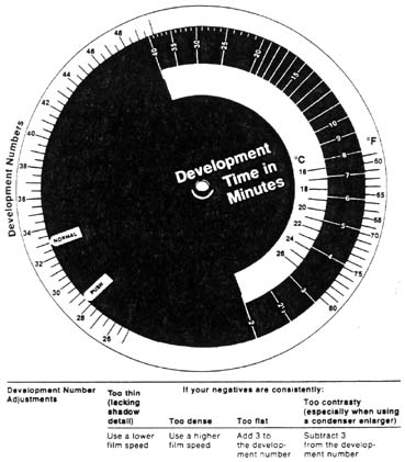
Development Dial
Set for development number 33 (Tri-X Pan in D-76) See next page.
—————————————————————————————————
| Development Number | Too thin | If your negatives are consistently: |
||
| Adjustments | (lacking | Too contrasty | ||
| shadow | especially when using | |||
| detail) | Too dense | Too flat | a condenser enlarger | |
| Use a lower film speed |
Use a higher film speed |
Add 3 to the develop- ment number |
Subtract 3 from the develop- ment number |
|
This and the following page are taken from: Kodak Black-and-White Darkroom Dataguide, 7th edition, publication # R-20, Eastman Kodak Company, 1980.
DEVELOPMENT NUMBERS
Development Numbers for Kodak Developers |
|||||||
| Kodak Black-and-White Films | |||||||
| D-76 (1:1) | Microdol-X | DK-50 | HC-110 | HC-110 | |||
| 35 mm Films | D-76 | Microdol-X | (1:3) | (1:1) | Polydol | Dil.A | Dil.B |
| Panatomic-X | 32 | 36 | 42 | NR | 33 | NR | 30Ẅ |
| Plus-X Pan | 33 | 36 | 42 | NR | 33 | NR | 32 |
| Tri-X Pan | 37Ẅ | 40 | 46 | 34Ẅ | 36 | 28 | 36Ẅ |
| Recording 2475 | NR | NR | NR | NR | NR | 31 | 38Ẅ |
| High Speed Infrared | 41 | NR | NR | NR | NR | NR | 34 |
| Technical Pan 2415 | See Film Instructions | ||||||
| Roll Films | |||||||
| Panatomic-X Professional |
32 |
36 |
42 |
NR |
33Ẅ |
NR |
30Ẅ |
| Verichrome Pan | 36 | 38Ẅ | 43Ẅ | NR | 34 | NR | 32 |
| Tri-X Pan | 37Ẅ | 40 | 46 | 34Ẅ | 36 | 28 | 36Ẅ |
| Tri-X Pan Professional | 37Ẅ | 40 | NR | 37Ẅ | 39 | NR | 39 |
| Plus-X Pan Professional |
33 |
36 |
41 |
NR |
33 |
NR |
32 |
| Royal-X Pan | NR | NR | NR | NR | 36 | 34 | 40 |
| Sheet Films | DK-50 | ||||||
| Royal-X Pan 48166 | NR | NR | 34 | NR | 38 | 34 | 40 |
| Royal Pan 4141 | 40 | 41 | 32 | 37Ẅ | 37Ẅ | NR | 36Ẅ |
| Tri-X Pan Professional 4164 |
36 |
39 |
NR |
35 |
37Ẅ |
NR |
36Ẅ |
| Super-XX Pan 4142 | NR | NR | 32 | 38 | 38Ẅ | 29Ẅ | 35 |
| Plus-X Pan Professional 4147 |
37Ẅ |
40 |
NR |
34 |
37Ẅ |
NR |
36 |
| Tri-X Ortho 4163 | 36Ẅ | 39 | NR | 35 | 37Ẅ | NR | 36Ẅ |
| Ektapan 4162 | 40 | 43 | NR | 34 | 40 | 28Ẅ | 34 |
NR = not recommended
| How to find the development time |
Find the development number for your film and
developer above. Set the NORMAL pointer at the development number and read the development time opposite the temperature of the developer. Push Processing—Use the PUSH pointer instead of the NORMAL pointer to determine development times. See page 14 for details |