| This version reflects the comments of the core participants as reviewed and incorporated in accordance with CORD's FIPSE-supported Curriculum Morphing Project. | |||||||||||||||||||||||||||||||||||||||||||||||||||||||||||||||||||||||||||||||||||||||||||||||||||||||||||||||||||||||||||
MODULE 4-7 ELECTRO-OPTIC AND ACOUSTO-OPTIC DEVICES General Comments of John Simcik lectro-optic and acousto-optic devices are used with lasers as Q-switches, beam deflectors, modulators, and mode-lockers. The electro-optic effect is a change in the index of refraction for certain crystals as a function of applied voltage. The index change is dependent on the direction and polarization of the incident beam. The acousto-optic effect involves an interaction between sound waves and light waves traveling through other types of crystals. The acousto-optic effect can be used to control the frequency, intensity, and direction of an optical beam.
When you complete this unit, you will be able to: 1. Describe the operation of electro-optic devices and give a list of potential applications. 2. Define extinction ratio as it applies to an electro-optic modulator. 3. Given the relevant parameters, calculate the transmission of an electro-optic modulator. 4. Define the difference in operation for an electro-optic modulator operated in the longitudinal and transverse modes. Draw a diagram illustrating each configuration. Compare the characteristics of each mode. 5. Describe the operation of acousto-optic devices and give a list of potential applications. 6. Draw and label a block diagram of a simple acousto-optic beam-deflection system. 7. State the equation for the rise time for an acousto-optic modulator as a function of laser beam diameter. Calculate and plot the rise time as a function of the diameter for a given acoustic velocity. 8. Given the necessary parameters, calculate the deflection angle for an acousto-optic light-beam deflector. 9. Compare the speed and number of resolvable spots for electro-optic and acousto-optic light-beam deflectors. 10. Use an electro-optic modulator to modulate a beam of laser light. Measure the half-wave voltage, the extinction ratio, and the modulation frequency. From the measured values, calculate the birefringence as a function of applied voltage. 11. Set up and operate an acousto-optic beam deflector. Adjust the drive frequency of the deflector and measure the deflection of a laser beam.
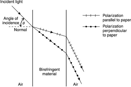
Electro-Optic Modulators In this section, we discuss the operation and application of electro-optic devices that rely on the phenomenon of birefringence that is induced by application of voltage to a crystal. Let us first define birefringence. In certain crystalline materials, an incident light ray will separate into two rays that may travel in different directions. These crystals are called birefringent. The direction in which the light travels is dependent on its polarization. For each of the two different perpendicular states of polarization, the light will travel in a different direction. Birefringence is also called double refraction because when the light enters the crystal, it is refracted into two different directions. Figure 1 shows the effect of birefringence when a beam of unpolarized light enters the surface of a birefringent material at an angle q to the normal to the surface. The two different components of polarization (horizontal and vertical) travel in two different directions. The material has two different indices of refraction, one for each of the two perpendicular components of polarization. In accordance with the laws of geometric optics, the two rays are refracted at different angles as they enter the crystal.
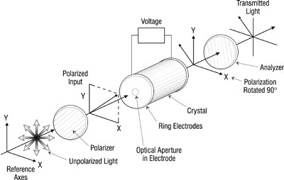
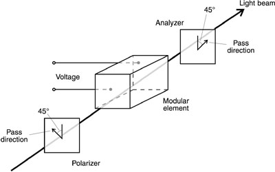
Fig. 1 Many crystalline materials exhibit birefringence naturally, without application of any voltage. The birefringence is present all the time. Examples of such crystals are quartz and calcite. There are also a number of crystals that are not birefringent naturally but in which application of a voltage induces birefringence. This phenomenon is called the electro-optic effect. The electro-optic effect leads to the ability to control light beams in a variety of ways and is the basis of a number of applications, including light-beam modulators, Q-switches, and deflectors. Examples of crystals that exhibit the electro-optic effect are potassium dihydrogen phosphate (commonly called KDP), ammonium dihydrogen phosphate (ADP), potassium dideuterium phosphate (KD*P), lithium niobate, and barium sodium niobate. The operation of an electro-optic device used as a light-beam modulator is shown schematically in Figure 2. Polarized light is incident on the modulator. The light may be polarized originally or a polarizer may be inserted, as shown. The analyzer, oriented at 90º to the polarizer, prevents any light from being transmitted when no voltage is applied to the electro-optic material. When the correct voltage is applied to the device, the direction of the polarization is rotated by 90° . Then the light will pass through the analyzer.
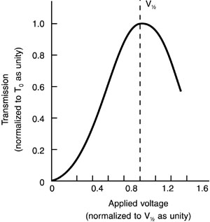
Fig. 2 Two types of electro-optic effect have been used: the Kerr electro-optic effect, which is shown by liquids such as nitrobenzene, and the Pockels electro-optic effect, shown by crystalline materials such as ammonium dihydrogen phosphate or lithium niobate. Some early electro-optic devices used nitrobenzene, but the liquid tends to polymerize in the presence of the intense laser light. Modern electro-optic modulators use the Pockels effect. The electro-optic modulators are often called Pockels cells. The orientation of the polarizer and analyzer at 45º to the vertical, as shown in Figure 1, is a common configuration, used with many commercial modulators. But the orientation depends on the particular material used and on the direction in which the crystal has been cut. The manufacturer’s instructions should be consulted to ensure proper orientation of the modulator and the directions of the pass axes for the polarizer and analyzer. With the direction of polarization at 45º to the vertical direction, the polarization vector is composed of two perpendicular components of equal intensity, one vertical and one horizontal. The crystalline element is oriented with its axes in a specified orientation (which depends on the crystalline symmetry of the particular material). The applied voltage induces birefringence in the crystal, so that the two components of polarization travel with different velocities inside the crystal. This induced birefringence is the basis of the electro-optic effect. The two components travel in the same direction through the crystal and do not become physically separated. But the two components, in phase as they enter the crystal, emerge with different phases. As they traverse the crystal, they accumulate a phase difference, which depends on the distance traveled and on the applied voltage. When the beams emerge from the crystal, the polarization of the combined single beam depends on the accumulated phase difference. If the phase difference is one-half wavelength, the polarization is rotated by 90º from its original direction. This by itself does not change the intensity of the beam. But, with the analyzer, the transmission of the entire system varies, according to T = T0 sin2(p D nL/l ) Equation 1 where T is the transmission, T0 the intrinsic transmission of the assembly, taking into account all the losses, D n the birefringence (that is, the difference in refractive index for the two polarizations), L the length of the crystal, and l the wavelength of the light. The birefringence is an increasing function of the applied voltage, so that the transmission of the device will be an oscillatory function of applied voltage. The maximum transmission occurs when D n = l /2L Equation 2 This occurs at a voltage called the half-wave voltage, denoted V1/2. The half-wave voltage depends on the nature of the electro-optic material. The half-wave voltage for a particular material increases with the wavelength. Thus, in the infrared the required voltage is higher than in the visible. This factor can limit the application of electro-optic modulators in the infrared. The transmission of an electro-optic device as a function of applied voltage is shown in Figure 3, indicating the maximum transmission at the half-wave voltage.
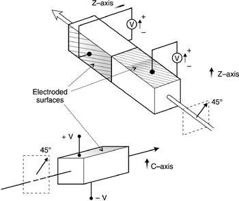
Fig. 3 In most crystals, each of the prominent crystalline faces belongs to one of three families of planes that intersect along what are called crystal axes. These axes can be designated as coordinate axes, even though they are not generally at right angles to each other. When one fabricates an electro-optic modulator, the crystal must be cut at certain specified angles to the crystalline axes. A full discussion of the different orientations and the reasons for them is beyond the scope of this module. We simply note that different crystalline symmetries require that specific relations be maintained between the crystalline axes and the faces of the electro-optic element. One important performance parameter for electro-optic modulators is the extinction ratio, defined as the ratio of the transmission when the device is fully open, to the transmission when the device is fully closed. In practice there is always some light leakage, so the minimum transmission never reaches zero. A high value of the extinction ratio is desirable because it determines the maximum contrast that may be obtained in a system that uses the modulator. Commercial electro-optic modulators can have extinction ratios in excess of 1000. Electro-optic modulators may be fabricated with different physical forms. In one form, voltage is applied parallel to the light propagation, as was shown in Figure 2. One uses transparent electrodes or electrodes with central apertures. This is called a longitudinal electro-optic modulator. In another form, metal electrodes are on the sides of the crystal (which has a square cross section) and the voltage is perpendicular to the light propagation. This is called a transverse modulator. Two examples are shown in Figure 4. The top is a two-element configuration suitable for use with materials like ADP. The use of two crystals oriented as shown provides compensation for the natural birefringence of the material. The bottom portion of the figure shows a single-element configuration suitable for lithium tantalate-type materials. Both single- and dual-element configurations are in use in commercial modulators.
Fig. 4 Longitudinal and transverse modulators have different applications. Longitudinal modulators may have large apertures, but the half-wave voltage will be high, often in the kilovolt range. Longitudinal modulators are often used with conventional light sources. Because it is difficult to vary the required high voltages rapidly, the frequency response of longitudinal modulators tends to be low. Applications for which longitudinal modulators are suited include relatively low-frequency modulation of laser beams or use with non-laser sources. In transverse modulators, the voltage is applied perpendicular to the light propagation. The phase retardation for a given applied voltage may be increased simply by making the crystal longer. The half-wave voltage thus may be much lower for transverse modulators, perhaps as low as 100 volts. It follows that the frequency response may be much higher. Transverse modulators are thus suited for fast, broadband applications. A problem with transverse modulators is the relatively small aperture that they permit, because the crystal may be a long, thin parallelepiped. This physical configuration means that transverse modulators are best suited for use with narrow, well-defined laser beams. In addition, the extinction ratios available with transverse modulators tend to be lower than for longitudinal modulators. Applications of transverse modulators include broadband optical communication, display and printing systems, and fast image and signal recorders. Table 1 lists electro-optic materials and some of their characteristics. The table includes the names of a number of electro-optic materials, their common abbreviations, their chemical formulas, and the spectral range over which they are transmissive. The bandwidths quoted are for use of the materials in commercially available electro-optic light modulators. Most of the materials are suited for use in the visible and near-infrared portions of the spectrum, but cadmium telluride is useful as a modulator for CO2 lasers in the long-wavelength infrared. Of the materials in the table, ADP, AD*P, and KD*P are relatively older materials. They may be used as either longitudinal or transverse modulator materials, but have relatively high half-wave voltages. Lithium niobate and lithium tantalate represent a relatively modern class of electro-optic materials, which have larger electro-optic effects and smaller half-wave voltages. They are hard to grow in large crystals of high quality but they are perhaps the best available modern electro-optic materials.
The speed of electro-optic modulators is expressed as a bandwidth, i.e., the rate at which the device can be turned on and off. The bandwidth of electro-optic modulators can be very large, up to hundreds of megahertz. The speed is limited mainly by the ability to produce voltage pulses of sufficient amplitude at high frequency. We summarize some of the advantages and drawbacks of electro-optic devices as light-beam modulators. Electro-optic modulators have higher speed and larger bandwidth than competing technologies (mechanical and acousto-optic devices). Electro-optic devices have some limitations, including their relatively high voltage requirements and limited beam-diameter capabilities.
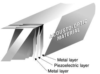
Acousto-Optic Modulators A different approach to modulator technology uses the interaction between light and sound waves to produce changes in optical intensity, phase, frequency, and direction of propagation. Acousto-optic modulators are based on the diffraction of light by a column of sound in a suitable interaction medium. When a sound wave travels through a transparent material, it causes periodic variations of the index of refraction. The sound wave can be considered as a series of compressions and rarefactions moving through the material. In regions where the sound pressure is high, the material is compressed slightly. This compression leads to an increase in the index of refraction. The increase is small, but it can produce large cumulative effects on a light wave passing some distance through the compressed material. An acousto-optic device requires a material with good acoustic and optical properties and high optical transmission. Several types of material are available. We shall describe acoustic-optic materials in more detail later. The sound wave is produced by a piezoelectric transducer. Piezoelectric materials exhibit slight changes in physical size when voltage is applied to them. An example of one such material is crystalline quartz. If the piezoelectric material is placed in contact with the acousto-optic material and a high-frequency oscillating voltage is applied to the piezoelectric material, it will expand and contract as the voltage varies. This in turn exerts pressure on the acousto-optic material and will launch an acoustic wave (sound wave) which will travel through the material. The frequency F of the acoustic wave will be the same as the frequency of the applied voltage. The acoustic wave will have a wavelength L given by: FL = C Equation 3 where C is the velocity of sound in the material, typically of the order of 105 cm/sec. Variation of the acoustic frequency of the driver will thus change the acoustic wavelength, which in turn changes the characteristics of the acousto-optic interaction. A typical structure for an acousto-optic device is shown in Figure 5. The piezoelectric materials and metal layers are bonded or deposited on the acousto-optic material. A radio-frequency field is applied across the piezoelectric material using the metal layers as electrodes. The acoustic wave is then launched into the acousto-optic medium by the piezoelectric material. Acoustic waves propagating from a flat piezoelectric transducer into a crystal will form almost plane wavefronts traveling in the crystal. The opposite end of the material from the transducer should have an acoustic termination to suppress reflected acoustic waves.
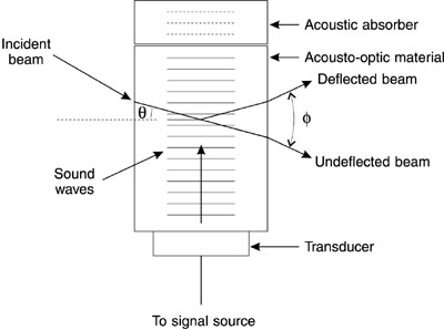
Fig. 5 The elasto-optic properties of the medium respond to the acoustic wave so as to produce a periodic variation of the index of refraction. A light beam incident on this disturbance is partially deflected in much the same way that light is deflected by a diffraction grating. The operation is shown in Figure 6. The alternate compressions and rarefactions associated with the sound wave form a grating that diffracts the incident light beam. No light is deflected unless the acoustic wave is present.
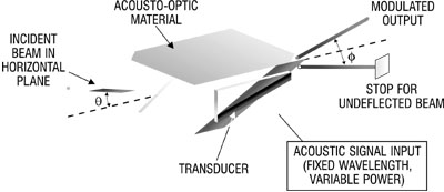
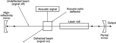
Fig. 6 For a material with a fixed acoustic velocity, the acoustic wavelength or grating spacing is a function of the radio-frequency drive signal; the acoustic wavelength controls the angle of deflection. The amplitude of the disturbance, a function of the radio-frequency power applied to the transducer, controls the fraction of the light that is deflected. Thus, the power to the transducer controls the intensity of the deflected light. Modulation of the light beam is achieved by maintaining a constant radio frequency, allowing only the deflected beam to emerge from the modulator and modulating the power to the transducer. Thus the modulator will be in its off state when no acoustic power is applied and will be switched to its transmissive state by the presence of acoustic power. The transmission T of an acousto-optic modulator is T = T0 sin2(p (M2PL/2H)0.5/l cos Q ) Equation 4 where P is the acoustic power supplied to the medium, l is the wavelength, L is the length of the medium (length of the region in which the light wave interacts with the acoustic wave), H is the width of the medium (width across which the sound wave travels), and the inherent transmission T0 is a function of reflective and absorptive losses in the device. The quantity M2 is a figure of merit, a material parameter that indicates the suitability of a particular material for this application. It is defined by M2 = n6p2/r v3 Equation 5 where p is the photoelastic constant of the material, r is its density, and v is the velocity of sound in the material. This figure of merit relates the diffraction efficiency to the acoustic power for a given device. It is useful for specifying materials to yield high efficiency, but in practical devices, bandwidth is also important, so that specifying a high value of M2 alone is not sufficient. The angle Q is the so-called Bragg angle. The diffraction of the light beam by the periodic array of acoustic waves satisfies the same relationship as the scattering of X rays by periodic planes of atoms (so-called Bragg scattering). Hence the diffraction of the light waves is also referred to as Bragg reflection. Bragg reflection of X rays occurs at the planes of atoms in a crystal which are spaced a regular distance apart. The so-called Bragg angle gives the angle at which the most efficient reflection occurs. The phenomenon of optical reflection from the regular wavefronts of the acoustic waves is exactly the same, with the provision that the acoustic wavelength replaces the distance between planes of atoms. The Bragg angle Q is defined as the angle the beam makes with the reflecting waves. It is given by: sin Q = l /2nL Equation 6 where n is the index of refraction of the material, l is the optical wavelength and L is the acoustic wavelength. To use the acousto-optic device as a modulator, one should employ the deflected beam as shown in Figure 7. This will give higher values of the extinction ratio than using the undeflected beam. When the acoustic drive is off, the light in the direction of the deflected beam is zero. When the acoustic drive is on, light is diffracted into that direction. Thus, the acousto-optic device controls the light in that direction, turning it on and off at will. The device is operated as a modulator by keeping the acoustic wavelength (frequency) fixed and varying the drive power to vary the amount of light in the deflected beam. As we shall see later, the use as a light-beam deflector is somewhat different.
Fig. 7 The design and performance of acousto-optic beam modulators have several limitations. The transducer and acousto-optic medium must be carefully designed to provide maximum light intensity in a single diffracted beam, when the modulator is in an open condition. The transit time of the acoustic beam across the diameter of the light beam imposes a limitation on the rise time of the switching and therefore limits the modulation bandwidth. The acoustic wave travels with a finite velocity and the light beam cannot be switched fully on or fully off until the acoustic wave has traveled all the way across the light beam. Therefore, to increase bandwidth, one focuses the light beam to a small diameter at the position of the interaction so as to minimize the transit time. Frequently the diameter to which the beam may be focused is the ultimate limitation for the bandwidth. If the laser beam has high power, it cannot be focused in the acousto-optic medium without damage. General Comments of John Simcik The rise time tr for an acousto-optic modulator is given by the equation: tr = d/C Equation 7 where d is the diameter of the laser beam in the region of the interaction and C is the velocity of sound in the material. As an example, for a tellurium dioxide acousto-optic modulator, with an acoustic velocity of 8.03 ´ 105 cm/sec and a laser-beam diameter of 100 m m, the rise time is 0.01 cm/8.03 ´ 105 cm/sec = 1.245 ´ 10- 8 = 12.45 nsec. Thus acousto-optic devices are capable of high-frequency modulation. Acousto-optic light-beam modulators have a number of important desirable features. The electrical power required to excite the acoustic wave may be small, less than one watt in some cases. High extinction ratios are obtained easily because no light emerges in the direction of the diffracted beam when the device is off. A large fraction, up to 90% for some commercial models, of the incident light may be diffracted into the transmitted beam. Acousto-optic devices may be compact and may offer an advantage for systems where size and weight are important. As compared to electro-optic modulators, they tend to have lower bandwidth, but do not require high voltage. Table 2 presents the characteristics of some materials used in commercially available acousto-optic modulators. Several materials are available for use in the visible and near-infrared regions, and one material (germanium) is useful in the far infrared. The table also presents some values for the figure of merit M2, at a wavelength of 633 nm, except for GaAs (1530 nm) and Ge (10.6 mm). The factors that enter into the definition of M2 vary with crystalline orientation; the values in the table are for crystals oriented to maximize M2. The values for bandwidth and for typical drive power are representative of commercially available acousto-optic devices.
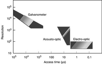
Light-Beam Deflectors Light-beam deflectors, sometimes called scanners, form an important class of accessory that is required for applications such as display optical processing and optical data storage. Three main methods of light-beam deflection are commonly used: mechanical (i.e., galvanometer-type), electro-optic, and acousto-optic. The capabilities of these three types of systems are compared in Figure 8. Light-beam deflection is measured in terms of "resolvable spots," rather than in terms of the absolute angle of deflection. One resolvable spot means that the beam is deflected by an angle equal to its own angular spread. The access time is the random-access time to acquire one specific spot or resolution element. The figure indicates that mechanical methods give the largest number of resolvable spots, but are slowest, whereas electro-optic devices are fastest, but have the smallest number of resolvable spots. The figure characterizes the speed in terms of random access time to reach any desired spot. This is a useful parameter for applications like a random-access memory. Another possible method of characterizing speed would be the spot scan rate during a sequential scan. This would be useful for applications like imaging or projection display. Again the mechanical systems are slowest and the electro-optic fastest, but the difference is less pronounced than for the random-access time. We shall now describe the electro-optic and acousto-optic methods in more detail.
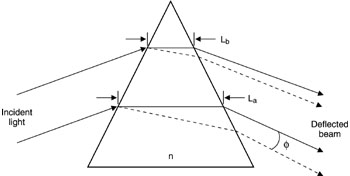
Fig. 8 Electro-optic deflectors use prisms of electro-optic crystals like lithium niobate. A voltage is applied to the crystal and changes the index of refraction of the material, and hence the direction of propagation of the beam traveling through the prism. Figure 9 illustrates the operation of such a device.
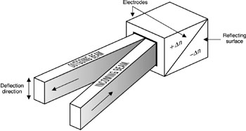
Fig. 9 The deflection angle for a plane wave passing through such a prism is obtained by applying Snell’s law at the boundaries of the prism. The number N of resolvable spots is N = D n(La - Lb)/e l Equation 8 where D n is the change in the index of refraction, which is a function of the applied voltage, La and Lb are the widths defined in Figure 9, e is a factor of the order of unity, and l is the wavelength. A method of construction for a useful beam deflector is shown in Figure 10. This uses two prisms, one with a positive value of D n and one with a negative value, when voltage is applied to the electrodes as shown.
Fig. 10 Electro-optic deflectors exhibit very fast response and short access time, but have relatively small numbers of resolvable spots, as Figure 8 showed. Other limitations are limited availability of electro-optic crystals with high optical quality throughout a sufficiently large volume, and relatively high requirements on operating power. Because of these factors, electro-optic deflectors are used less frequently than galvanometers, rotating mirrors, or acousto-optic devices. Most of the work done on electro-optic deflectors has been experimental; relatively few commercial models are available. Acoustic waves propagating from a flat piezoelectric transducer into a crystal form almost planar wavefronts in the crystal. Light rays passing through the crystal approximately parallel to the acoustic wavefronts are diffracted by the phase grating formed by the acoustic waves. The diffraction satisfies the Bragg condition, similar to the diffraction of X rays from planes of atoms in a crystalline lattice. The Bragg angle has been defined above in equation 6. The operation of acousto-optic devices has been illustrated in Figure 6 in connection with acousto-optic modulators. When an acousto-optic device is used as a modulator, one observes the diffracted beam at a fixed angle and varies the acoustic power to change the diffraction efficiency. When one uses an acousto-optic device as a deflector, one keeps the acoustic power constant but varies the acoustic wavelength so as to change the Bragg angle. Then F , the angle formed by the undiffracted and diffracted beams, is
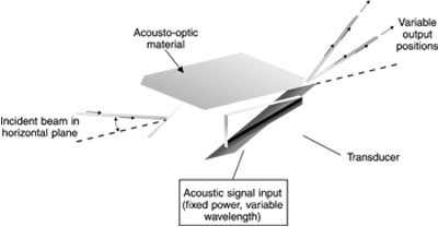
where l is the optical wavelength and The operation of an acousto-optic device as a light-beam deflector is illustrated in Figure 11. The drive power is kept constant and the acoustic wavelength (frequency) is varied, to deflect the beam to different angular positions. This is different from the way the device is used as a modulator (Figure 8).
Fig. 11 The bandwidth is limited by the time it takes for the acoustic wave to propagate across the diameter of the light beam, the same limitation that applies to the acousto-optic modulator. Acousto-optic deflectors offer several advantages: • easy control of deflection modes and position • simple structure • wide variety of uses from a single deflector • larger number of resolvable spots than electro-optic devices • faster access than mechanical devices The capabilities of acousto-optic deflectors have been shown in Figure 8. Commercial models offer up to 1000 resolvable spots, with access times typically in the range of 5-50 microseconds. Two-dimensional deflection may be obtained by using two deflectors in series, with their directions of deflection at right angles. Acousto-optic deflectors have been employed in applications such as high-frequency scanning and optical signal processing. A variety of different types of Q-switch has been developed. As we describe them, we shall use a solid-state laser as an illustration, but the basic methods are applicable for other types of lasers also.
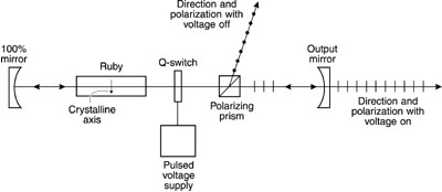
Q-Switches Q-switching methods all employ a variable attenuator between the laser rod and the output mirror. During the time the rod is being pumped to a highly excited state, the attenuator is opaque and laser action is inhibited. When the attenuator is suddenly switched to a transparent condition, the laser rod can "see" the output mirror. The energy stored in the rod can be extracted by the stimulated-emission process and emitted through the output mirror in a short, high-power pulse. The various types of attenuator that can be used define three other classes of Q-switch. The three types of variable attenuator that have been used most widely are electro-optic elements, acousto-optic elements, and bleachable dyes. Bleachable dyes, although least expensive, tend to open irregularly so that, for the highest performance, electro-optic or acousto-optic Q-switches are preferred. The use of electro-optic and acousto-optic elements as light modulators has been described earlier. It is apparent that a Q-switch is a specialized type of modulator. The operation of an electro-optic Q-switch for a solid-state laser is shown schematically in Figure 12. The solid-state crystal is ruby, because when the ruby rod is oriented as shown, the light emitted from the rod is polarized in a horizontal direction. The analyzer will prevent the light from reaching the output mirror. When voltage is applied to the electro-optic switch, the plane of polarization of the light is rotated 90° . Then light from the rod passes through the analyzer and reaches the mirror. Electro-optic Q-switches use the Pockels effect in crystalline materials like potassium dideuterium phosphate. They are extremely fast, with opening times around one nanosecond. They are used most often at shorter wavelengths, in the visible spectrum, because the half-wave voltage increases at longer wavelengths.
Fig. 12 Acousto-optic Q-switches rely on the diffraction grating set up by sound waves in certain materials, as described earlier. The light beam is deflected from its path by diffraction when the sound wave is present. The operation of an acousto-optic Q-switch is shown in Figure 13. When the acoustic wave is present, some of the light is diffracted and misses the mirror. The deflection angle, a small fraction of one degree, is exaggerated in the figure. The loss due to diffraction is enough to keep the laser below threshold. When the pumping of the laser is complete, the acoustic wave is switched off. Then all the light reaches the mirror and a laser pulse builds up rapidly. The most commonly encountered acoustic Q-switch uses fused silica. The opening time is typically around 100 nanoseconds, longer than for the electro-optic device. General Comments of John Simcik
Fig. 13 Acousto-optic devices have proved to be the most useful type for Nd:YAG lasers. The voltage required for operation of an electro-optic device increases with wavelength, a disadvantage for infrared applications. Bleachable dyes for Q-switching in the infrared are less developed than those for use in the visible. Thus acousto-optic devices are most useful for Nd:YAG Q-switching.
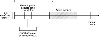
Mode-Lockers Within a Q-switched laser pulse there may be further substructure. This arises because of a phenomenon called mode-locking. If a number of longitudinal modes is present in the laser output, these modes may interfere and lead to an oscillatory behavior for the output. Thus, within the envelope of the Q-switched pulse, there may be a train of shorter pulses. If only a single longitudinal mode is present in the laser output, there will be opportunity for mode-locking. In many lasers, a number of longitudinal modes will be present simultaneously. Ordinarily, the phases of these modes will be independent of each other. But under some conditions, the modes can interact with each other and their phases can become locked together. Then the behavior of the output will contain a train of short, closely spaced pulses within the Q-switched pulse. Mode-locking may be accomplished intentionally by introducing a variable loss into the cavity, such as an electro-optic or acousto-optic modulator, so that the gain of the cavity is modulated at the frequency c/2L, which is the difference in frequency between adjacent longitudinal modes. Here c is the velocity of light and L is the length of the laser cavity. In the time domain, the output of the mode-locked laser consists of a series of very short pulses. From a simple point of view, one may consider that there is a very short pulse of light bouncing back and forth between the laser mirrors. Each time the pulse reaches the output mirror, a mode-locked pulse emerges from the laser. The result is a series of short pulses separated in time by 2L/c, the round-trip transit time of the cavity. The duration of these pulses is very short, often of the order of a few picoseconds. Hence, a laser operating in this fashion is often called a picosecond pulse laser. The mode-locking behavior is encouraged by inserting a modulator in the laser cavity near the output mirror and opening the modulator at a frequency c/2L. This is shown in Figure 14.
Fig. 14 The minimum duration for a mode-locked pulse is equal to D n , where D n is the spectral width of the active medium. For an Nd:glass laser, the spectral width is large, around 1012 Hz. The minimum pulse duration for such a laser is then around 1 picosecond. The shortest pulses that have been produced have come from liquid-dye lasers, for which the spectral width can be very large. Pulses as short as 30 femtoseconds (30 ´ 10- 15 sec) have been produced. This is remarkable in that the total duration of the pulse contains only a few cycles of the high-frequency electric field. One may obtain a single pulse with this duration by using an output coupler such as an electro-optic switch that opens long enough to let one pulse emerge from the train of output pulses and then closes again.
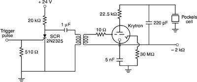
Drivers for Electro-Optic Devices Electro-optic devices require relatively high voltages, typically of the order of kilovolts for longitudinal devices and a hundred volts to a few hundred volts for transverse devices. The power supplies that are used to supply them may be ordinary laboratory power supplies if the frequencies are not too high. Any power supply or function generator that can supply the required half-wave voltage at the required frequency will generally be adequate. The Pockels cell represents a capacitive load, so the power dissipation is not excessively high. If the frequency is high or a very rapid rise time is required, it becomes more difficult to switch the required values of voltage at high speed. One circuit that has been employed for driving Pockels cell modulators at high speed is shown in Figure 15. This circuit uses a switching tube called a krytron. This is a gas-filled tube that has the capability of shorting out voltages in the 3- to 7-kilovolt range. The trigger pulse that initiates the operation of the switch is delivered through a silicon-controlled rectifier (SCR) and transformer. This circuit is capable of switching the Pockels cell modulator at speeds in the nanosecond range. The chief drawback of the circuit is the limited lifetime of the tube.
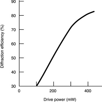
Fig. 15. Drive circuit for electro-optic Pockels cell The manufacturers of commercial electro-optic light-beam modulators, deflectors, and Q-switches generally also supply a line of power supplies for their devices. The voltages and impedances of particular power supplies are matched to the requirements of individual electro-optic devices. The rise times for some of these voltage drivers may be less than one nanosecond. Drivers for Acousto-Optic Devices The drive circuit for an acousto-optic device may be an electrical signal generator that delivers a periodic voltage to the electrodes attached to the piezoelectric material bonded to the acousto-optic device. A simple radio-frequency generator may suffice. The generation of the acoustic waves does dissipate power, so some drive power is necessary. Usually a few watts is sufficient. Figure 16 shows how the drive power affects the performance of a commercial acousto-optic device. The figure shows the diffraction efficiency as a function of drive power. The diffraction efficiency is the optical power in the diffracted beam divided by the incident optical power. The diffraction efficiency increases with drive power and then saturates at a value near 100%. This means that almost all the incident light gets into the diffracted beam. For this example, it takes only a few hundred milliwatts to reach high values of diffraction efficiency. For other devices, it may take several watts.
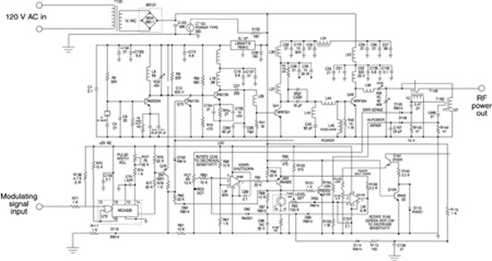
Fig. 16 As one example of the complexity that a drive circuit for an acousto-optic device can take, Figure 17 shows a circuit that has been developed to drive a 50-watt, 24-MHz laser Q-switch.
Again, the manufacturers of commercial acousto-optic light-beam modulators, deflectors, and Q-switches generally also supply a line of power supplies for their devices. The voltages and impedances and drive power capabilities of particular power supplies are matched to the requirements of individual acousto-optic devices. The frequencies of these power supplies are often in the range of hundreds of megahertz.
Helium-neon laser (one with plane polarized output preferred) Electro-optic modulator DC power supply for modulator Sine-wave variable-frequency power supply for modulator Power meter compatible with laser Photodiode detector and appropriate circuitry Oscilloscope and cables Sheet polarizer Polarizing prisms (one if He-Ne laser output is plane polarized, otherwise, two) Angular rotation mount Acousto-optic light-beam deflector Acoustic signal generator (power supply) Angular rotation mount for deflector Screen Meter stick
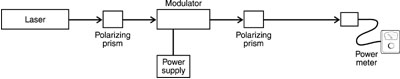
First you will operate an electro-optic modulator and measure some of its characteristics. In these procedures, observe all appropriate safety procedures, and use laser protective eyewear according to the rules of your laboratory. You will need a beam of plane polarized light from the helium-neon laser. Determine the polarization of the laser light by placing a piece of sheet polarizer in the beam, mounted on the angular rotation mount. Direct the beam emerging from the polarizer into the power meter. Rotate the polarizer through 360° and observe the variation of the power meter. If the beam is plane polarized, the reading of the power meter should decrease to zero at two positions 180° apart. At angles that are 90° from the positions where the intensity is zero, the intensity will rise to a maximum. In this case, when the laser output is plane polarized, it may be used as is. If the light passing through the polarizer does not decrease to zero at two positions 180° apart, it is not plane polarized. It may be unpolarized (intensity does not change as the polarizer is rotated) or partially polarized (intensity goes through two minima 180° apart, but the minima are greater than zero). In either case, a polarizing prism must be used to yield plane polarized light. Use a polarizing prism rather than sheet polarizer. The prism will give better results. Direct the beam through the polarizing prism. The beam emerging from the prism should be plane polarized. Check it again, using the sheet polarizer, to be sure. Now set up the electro-optic modulator and use it to modulate the laser beam. Set up the experimental arrangement shown in Figure 18. The first polarizing prism will not be required if the laser was originally plane polarized. Carefully align the modulator so that the light beam passes accurately along the axis of the device and emerges with minimum loss of intensity. Mount the second polarizing prism on an angular rotation mount so that the beam passes through it and enters the power meter. Rotate the prism until the light transmitted through it is at a minimum. The minimum should be near zero.
Fig. 18 The orientation of the polarizer and analyzer at 45° to the vertical, as shown in Figure 19, is a common configuration, used with many commercial modulators, especially modulators employing materials like ADP. But the orientation depends on the particular electro-optic material used and on the direction in which the crystal has been cut. Consult the manufacturer’s instructions to ensure proper orientation of the modulator and the orientation of the pass directions for the polarizer and analyzer.
Fig. 19 Next connect the DC power supply to the electrical connectors on the case of the modulator. Turn on the power supply and gradually increase the voltage from zero. Observe the increase in the light reaching the power meter. As you increase the voltage in steps, record the voltage and the power meter reading at each step. The power meter reading should increase with increasing voltage at first. Then a maximum reading will be reached and, with further increase in voltage, the power meter reading should begin to decrease. When you have reached this point, you may terminate this part of the measurement. The value of the voltage at which the power is maximum is the half-wave voltage. Plot the power meter reading as a function of the applied voltage and determine the value of the half-wave voltage. Determine the extinction ratio for the modulator. The extinction ratio is the power meter reading when the applied voltage is equal to the half-wave voltage divided by the power meter reading when the voltage is zero. Use the plot of power versus applied voltage to derive the birefringence D n as a function of applied voltage. Use the equation:
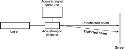
P(V) = P(V1/2) ´ sin2 (p D n/l ) to determine D n as a function of voltage V. Here P(V) is the meter reading at voltage V, P(V1/2) is the meter reading at the half-wave voltage V1/2, L is the length of the crystal, and l is the wavelength (632.8 nm). You will need to determine the value of L. Either use the value specified by the manufacturer or carefully measure the length of the crystal. Solve the equation above for D n at several values of voltage V, using the values of P(V) obtained above. Then plot D n as a function of voltage V. Next, you will modulate the light at a high frequency. Remove the DC power supply and connect the sine-wave generator to the modulator. Replace the power meter with the photodiode and direct the beam onto the photodiode. Connect the output of the photodiode circuit to the oscilloscope input. Turn on the power supply and adjust the voltage so that the peak of the sine wave is equal to the half-wave voltage. This will lead to maximum contrast in the modulated beam. Observe the output of the detector on the oscilloscope. The scope trace should show a modulated output. Vary the frequency of the sine-wave generator and observe how the oscilloscope signal changes. With the frequency of the sine-wave generator set at a fixed value, measure the frequency of the modulation. Measure the time between successive maxima in the intensity of the modulated signal. Use the known sweep speed of the oscilloscope to make this measurement. Calculate the frequency of the modulation, which is equal to the reciprocal of the time just measured. Compare this frequency to the frequency of the sine wave produced by the sine-wave generator. Next you will operate an acousto-optic light-beam deflector. Set up the experimental arrangement shown in Figure 20. The acousto-optic device should be inserted in an angular rotation mount. Angular adjustment is needed so that the light beam intersects the acoustic wavefronts at the Bragg angle. It is possible to calculate the Bragg angle and set the acousto-optic device in place at the proper angle, but it is usually more simple to rotate the device until optimum operation is obtained.
Fig. 20 During the initial alignment, the drive power from the signal generator should be off. When the acousto-optic device is in place, turn on the laser, but do not turn on the signal generator. Adjust the position of the laser beam and the acousto-optic device so that the beam passes undeflected through the acousto-optic device. The undeflected beam should emerge from the acousto-optic device traveling in the same direction as the original beam. Adjust the alignment until this occurs. Turn on the signal generator and increase the drive power until most of the light goes into the deflected beam. Project the deflected beam onto the screen, at a distance of several meters from the deflector. The drive power will be kept constant and the frequency will be varied. This will change the acoustic wavelength and will deflect the beam. The deflection of the beam will be observed through movement of the spot of light on the screen. To observe the deflection, vary the acoustic frequency and note how the spot of light moves across the screen. Measure the total distance on the screen through which the beam can be deflected. It may be necessary to adjust the alignment so that the total motion of the spot stays on the screen. To measure the deflection angle, set the drive frequency at its lowest value. Determine the position x1 where the beam strikes the screen. Change the drive frequency to its highest value and measure the position x2 where the beam strikes the screen. Use the meter stick to measure the distance x1- x2. Now use the meter stick to measure the distance D from the deflector to the screen. Measure to the screen at the midpoint between x1 and x2. Calculate the maximum deflection angle f of the beam using the equation: sin (F /2) = |x1 – x2|/2D Compare the result to the specification for the detector. Now determine the number of resolvable spots that this deflector can achieve. First determine the beam-divergence angle of the laser, either by measuring it directly through measuring the beam diameter at a known large distance from the laser or by using the specification given by the laser manufacturer. Calculate the number of resolvable spots by dividing the beam-deflection angle f obtained above by the beam-divergence angle. Compare your result to the specified value for the acousto-optic deflector.
Electro-optic measurements
1. 2. 3. 4. 5. 6. 7. 8. 9. 10. 11. 12.
Distance between maxima on scope trace (divisions) ______ Scope sweep speed (microseconds per division) ______
Acousto-optic measurements Distance x1 - x2 (cm) ______ Distance D (m) ______
1. Describe the operation of electro-optic devices and give a list of potential applications. 2. Define extinction ratio as it applies to an electro-optic modulator. 3. An electro-optic modulator has an intrinsic transmission of 95% (5% insertion loss). The crystal in it is 3 mm long. A light beam with a wavelength of 633 nm is directed through it. Voltage is applied so that the induced change in index of refraction is 0.0001. Calculate the transmission of the electro-optic modulator. 4. Define the difference in operation for an electro-optic modulator operated in the longitudinal and transverse modes. Draw a diagram illustrating each configuration. Compare the characteristics of each mode. 5. Describe the operation of acousto-optic devices and give a list of potential applications. 6. Draw and label a block diagram of a simple acousto-optic beam-deflection system. 7. State the equation for the rise time for an acousto-optic modulator as a function of laser-beam diameter. Calculate and plot the rise time as a function of the spot diameter over the range from 10 to 1000 micrometers for a device fabricated from lithium niobate that has an acoustic velocity of 6.57 ´ 105 cm/sec. 8. An argon laser beam with wavelength 514.5 nm is directed through a tellurium dioxide
acousto-optic light-beam deflector excited by a 9. Compare the speed and number of resolvable spots for electro-optic and acousto-optic light-beam deflectors.
Berg, N. J., and J. N. Lee, editors. Acousto-Optic Signal Processing, Theory and Implementation. New York: Marcel Dekker, Inc., 1983. Goldstein, R. "Electro-Optic Devices in Review." Lasers and Applications, April 1986. Gottlieb, M., C. L. M. Ireland, and J. M. Ley. Electro-Optic and Acousto-Optic Scanning and Deflection. New York: Marcel Dekker, Inc., 1983. Higgins, T. V. "There is a lot more to an A-O modulator than meets the eye." Laser Focus World, July 1991: 133. Kaminow, I. P. An Introduction to Electro-optic Devices. New York: Academic Press, 1974. Korpel, A. Acousto-Optics. New York: Marcel Dekker, Inc., 1988. Main, R. P. "Fundamentals of Acousto-Optics." Lasers and Applications, June 1984: 111. Yariv, A. Quantum Electronics. 3rd ed. New York: Wiley, 1988.
|
|||||||||||||||||||||||||||||||||||||||||||||||||||||||||||||||||||||||||||||||||||||||||||||||||||||||||||||||||||||||||||