| This version reflects the comments of the core participants as reviewed and incorporated in accordance with CORD's FIPSE-supported Curriculum Morphing Project. | |||||||||||||||||||||||||||||||||||||||||||||||||||||||||||||||||||||||||
MODULE 4-5 (1) Arc lamps are continuous optical sources used to pump continuous-wave lasers and many pulsed solid-state lasers operating at low to moderate output power. They represent broadband sources with very high brightness. They have rated lifetimes of a few hundred hours. The most common arc lamps contain krypton and emit a spectrum of light well suited to excitation of Nd:YAG lasers. They typically generate more heat than flashlamps and adequate cooling is important. A possible explosion hazard presents a significant safety issue. 
1. Prepare a drawing showing the basic components of an arc-lamp power supply. Identify the function of each component. 2. Explain the purpose and operation of the trigger circuit for a continuous-arc lamp. 3. Prepare a drawing showing the difference in construction between arc lamps and flashlamps. Identify the difference and explain why they are made differently. 4. Identify different types of arc lamps, and list an application for each type. 5. Explain the failure mechanisms for arc lamps. Explain the effect of operation above rated current on lamp lifetime. 6. Describe safety measures that should be employed when one is working with arc lamps. 7. Demonstrate proper procedures for care of arc lamps. 8. Demonstrate starting procedures for arc lamps. 9. Measure the current voltage characteristic for an operating arc lamp and the output of an arc-lamp-pumped laser versus input current to the lamp. 10. Measure the ripple in the output voltage from an arc-lamp power supply.  Types of Arc Lamps
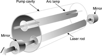
(2) Arc lamps are gas-discharge devices similar to flashlamps in design but intended to be operated continuously. There are two main types of arc lamps: linear lamps and short-arc lamps. The linear lamps are very like flashlamps, except for electrode design, having pointed cathodes instead of the rounded cathodes used in flashlamps. They are cylindrical in shape and have bore diameters that typically lie in the range between 4 and 7 mm and typically have arc lengths between 5 and 15 cm. They are filled with gas at a pressure usually between one and three atmospheres. They are well-suited to act as the pump sources for solid-state lasers, because the shape of the spectral emission is well-matched to the absorption of laser rods. A typical arrangement for pumping a solid-state laser with a linear arc lamp is illustrated in Figure 1.
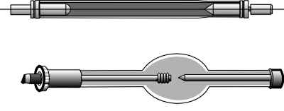
Fig. 1 (3) In short-arc lamps, the distance between electrodes is much shorter, typically less than one millimeter, so that these devices act essentially as point sources of light. They are suited for applications like illumination and exposure of photoresist. The structure of linear lamps and short-arc lamps is compared in Figure 2.
Fig. 2 (4) Arc lamps may be filled with a number of different gases, including krypton, xenon, mercury, and mercury-xenon. The linear krypton-filled arc lamp emits a spectrum that is well-matched to the absorption of Nd:YAG. Linear krypton arc lamps are used almost universally for pumping continuous Nd:YAG lasers and continuously pumped, repetitively pulsed Nd:YAG lasers. Since the Nd:YAG laser is the most common solid-state laser, for our purposes we will emphasize the linear krypton arc lamp. For completeness, we will describe briefly the other types of arc lamps and their applications. We shall also describe another lamp that is sometimes used to pump continuous solid-state lasers, the tungsten-halogen lamp, although it is not an arc lamp. (5) The discussion here is centered on conventional light sources useful for pumping of lasers. This module does not describe the growing use of semiconductor laser diodes for optical pumping of solid-state lasers.
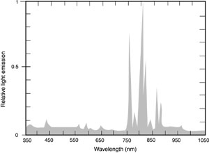
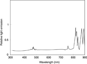
Krypton Arc Lamps (6) Krypton arc lamps emit a spectrum of light that is marked by a number of strong spectral lines in the 750-900-nm region. A typical example of the spectrum of a continuous krypton arc lamp is shown in Figure 3. This spectrum is similar to the spectrum of the krypton flashlamp with relatively low input energy, as shown in Figure 24 of Module 4-4. The level of excitation is similar in these two cases.
Fig. 3
(7) Because the peak absorption of Nd:YAG is in the 800-nm region, krypton arc lamps
make very effective pumps for Nd:YAG lasers. The absorption spectrum of Nd:YAG has been
shown in Figure 26 of Module 4-4. It has strong absorption in the same region where the
emission of krypton is high. As much as 40% of the light output of a krypton arc lamp can
be used for excitation of Nd:YAG under favorable circumstances. Thus, krypton arc lamps
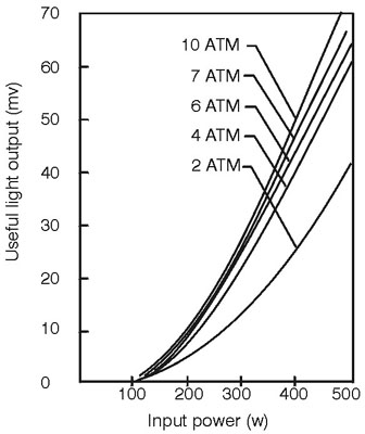
have (8) The useful light output of krypton arc lamps for excitation of Nd:YAG lasers increases rapidly with lamp input power, bore diameter, and gas fill pressure. Figure 4 shows how the light output of a krypton arc lamp increases with input power for a fixed bore diameter of 4 millimeters at several different fill pressures. Output increases rapidly with fill pressure up to about 4 atmospheres, but increases only slowly at higher pressures.
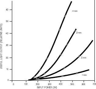
Fig. 4 (9) Figure 5 shows the useful light output as a function of lamp input power for krypton arc lamps filled to 6 atmospheres cold pressure and with several bore diameters. The output is a strong function of bore diameter up to a diameter around 4 millimeters, but increases more slowly at larger diameters.
Fig. 5 (10) Krypton arc lamps are available as both linear lamps and short-arc lamps, but the linear type is used for excitation of solid-state lasers. Table 1 shows characteristics of some representative high-power rod-seal continuous krypton arc lamps, suitable for pumping of solid-state lasers, to give an idea of what is commercially available. Rod-seal construction will be discussed in the section on mechanical characteristics.
*Based on information from EG&G Electro-Optics
Xenon Arc Lamps (11) Xenon arc lamps have a spectrum that is relatively broad and featureless throughout the visible and ultraviolet regions, in contrast to the strong line structure of the krypton arc lamp. Their spectral distribution closely matches the solar spectrum in these regions, so that they often are used as the light source for solar simulators. The spectrum of a typical xenon arc lamp is shown in Figure 6.
Fig. 6 (12) These arc lamps do have line structure in the infrared spectrum, but they are not so well-matched to the Nd:YAG absorption as the krypton lamp. They have been used to pump alexandrite lasers, however. (13) The relatively smooth spectral distribution also makes them useful for measurements of absorption and fluorescence. For these applications, the source wavelength is scanned with a wavelength-selecting element.
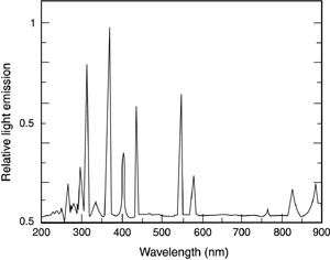
Mercury Arc Lamps (14) Mercury arc lamps feature a strong ultraviolet output with discrete lines. A spectrum for a typical mercury arc lamp is shown in Figure 7. It is apparent that the spectrum is dominated by strong discrete mercury lines through the ultraviolet and visible range. The emission spectrum extends into the deep ultraviolet, to wavelengths shorter than 300 nm.
Fig. 7 (15) These lamps contain mercury in liquid form at room temperature along with a small amount of starter gas, such as argon or xenon. The discharge begins in the starter gas. As the lamp warms, the mercury is vaporized and, after a warm-up period of five to ten minutes, the emission spectrum is dominated by the mercury lines. (16) Because of the strong ultraviolet spectrum, these lamps are often used in photochemical applications, such as exposure of photoresist, lithography, and curing of adhesives. Individual strong lines may be isolated by means of filters and used for excitation of fluorescence and spectroscopy.
Mercury-Xenon Arc Lamps (17) These lamps contain a mixture of mercury and xenon, with the xenon present at higher pressure than required as a starter gas. The discharge again begins in the xenon, and after warm-up the mercury lines are strong. But in this case the xenon lines are also strong so that the spectral output is a combination of mercury lines in the ultraviolet and xenon lines in the infrared. The spectrum of this type of lamp is essentially a combination of the xenon and mercury spectra shown in Figures 6 and 7. Such lamps are useful for research applications in which strong spectral lines are required over a broad wavelength range.
Short-Arc Lamps (18) Short-arc lamps are similar in their basic construction to linear arc lamps, but the length of the discharge between the electrodes is much shorter, in some cases as short as 0.25 mm. These lamps thus act essentially as point sources of light. They represent very-high-radiance sources, with brightness greater than any sources other than lasers. They are useful for applications such as solar simulation, illumination, projection, and ultraviolet exposure of materials. They are not useful as pump sources for solid-state lasers, because the shape of the arc is not well-matched to the shape of the laser rod. (19) Short-arc lamps are available with all the types of gas fill mentioned above.
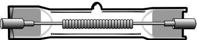
Tungsten-halogen lamps (20) The tungsten-halogen lamp is a filament lamp that has been used for pumping continuous solid-state lasers. It is illustrated in Figure 8. It is not an arc lamp, but is described here for completeness. It has been used in the past for pumping of Nd:YAG lasers, but appears not to be used in modern lasers as much as krypton arc lamps.
Fig. 8 (21) Tungsten-halogen lamps are low in cost and use relatively simple power supplies. They have also been used in motion pictures and theater lighting. (22) The distinguishing feature of tungsten-halogen lamps is the use of a halogen gas, instead of a vacuum, around the tungsten filament. A process called the halogen cycle increases the life of these lamps. In a filament lamp, tungsten is evaporated from the hot filament and deposited on the inside of the lamp envelope. This decreases light output because of envelope darkening, and eventually causes failure of the filament. In the halogen cycle, the gas, usually iodine or bromine, chemically reacts with the tungsten deposited on the envelope and converts it to tungsten halide gas. The gas diffuses back to the hot filament where the molecule is broken apart and the tungsten is redeposited on the filament. This has the desirable effects of extending filament lifetime and reducing the darkening of the envelope. In addition, it allows operation of the tungsten filaments at higher temperature than would be possible in vacuum. (23) The use of tungsten-halogen lamps appears to be less favored than krypton arc lamps for pumping of Nd:YAG lasers because of several factors. First, the efficiency of the lamps for excitation of Nd:YAG is less than that of krypton lamps. Also, tungsten-halogen lamps are not available in as high a range of power output as the krypton arc lamps. Finally, lifetime of the tungsten-halogen lamps is shorter than that of arc lamps. Still, tungsten-halogen lamps represent an extremely versatile and relatively low-cost light source with longer life than conventional filament lamps. (24) We now return to the discussion of linear krypton arc lamps and shall emphasize them for the remainder of the discussion.
Electrical Characteristics (25) The characteristics of electrical discharges in gaseous media were described in connection with Figure 1 of Module 4-2. These electrical characteristics are shared by arc lamps. At low voltage there is no current flow. As voltage increases, the current remains zero until some relatively high voltage is reached, at which point a very small current begins to flow. This current increases slowly until the breakdown voltage is reached. At the breakdown voltage a large number of gas molecules becomes ionized. Electrons are accelerated to velocities at which they can ionize more molecules through collisions. As current increases, the resistance of the gas decreases and the voltage required to sustain the discharge decreases with increasing current. This condition is called negative resistance and the current must be limited by inserting a positive resistance in the external circuit or the current will continue. An uncontrolled increase would lead to circuit damage. (26) Electrical characteristics of arc lamps, like flashlamps, may be discussed in terms of three different operating regimes:
(27) The power supply contains components to control the operation of the arc lamp in each of these regimes. We shall discuss this in detail in the section on power supplies for arc lamps. (28) In the triggering and unconfined-discharge stages, the arc lamp is similar to the flashlamp. But in stabilized operation, the arc lamp operates in a regime of lower current density. (29) The triggering process, the initiation of the electrical discharge in the gas, is similar to that discussed in Module 4-4 on flashlamps. Triggering begins with a spark streamer that crosses the gap between the electrodes and creates a conductive path between them. The voltage drop across this path should be less than the voltage supplied by the external circuit, so current will begin to flow through the lamp. (30) As with flashlamps, arc lamps may be triggered by application of an overvoltage to the lamp or by an external trigger. Some typical parameters for the triggering characteristics of commercial continuous krypton arc lamps were shown in Table 1. We shall return in the next section to a discussion of possible trigger circuits. (31) After the arc lamp is triggered, a relatively low value of current is flowing through the gas. The resistance of the gas is still relatively high, and the electrical discharge is undergoing expansion. The discharge in this regime is still a thin streamer, not filling the lamp. The discharge is said to be unconfined. The discharge region then begins to expand. As the power supply drives the lamp through this regime, the current increases and the resistance of the lamp drops. This stage also is similar to the unconfined-discharge stage in flashlamps. (32) At the end of this period of unconfined discharge, the current density in the discharge has increased to a value in the range 30-300 A/cm2. This is a value much lower than is characteristic of pulsed flashlamps, but thermal considerations will not allow continuous operation at the same current density encountered in flashtubes. The discharge has expanded, and fills the tube. It is stabilized by the presence of the envelope of the lamp, so that this regime is called wall-stabilized operation. After start-up, the lamp spends all its life in this regime. (33) Voltage/current characteristics of arc lamps are shown in Figure 9 for arc lamps operating in the stabilized continuous regime, for some different values of bore diameter. In this type of operation, we note that the resistance of the lamp is positive; that is, an increase of current requires an increase of voltage. This is in contrast to flashtubes, which generally operate in a region of negative resistance. Thus, issues are not as severe with current-limiting resistors in the operating circuit for arc lamps as they are with flashtubes. Some typical parameters for steady-state operation for representative continuous krypton arc lamps were shown in Table 1.
Fig. 9
Power Supplies for Arc Lamps (34) The power supply for an arc lamp contains three main components that correspond to the three operating regimes described in the section on electrical characteristics. The three main components are:
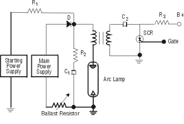
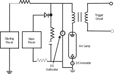
(35) A typical circuit for arc-lamp operation is shown in Figure 10. Exact values for voltages, currents, and circuit parameters will depend on the specific circumstances, including gas pressure, arc length, lamp diameter, and power required, but the figure does illustrate the basic elements, and the values indicated may be regarded as typical.
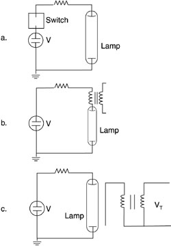
Main power supply: 100-300 V DC, 10-60 A Starting power supply: 1.5-2 kV DC, 10 mA R1: 200 kW R2: 10-50 W R3: 10 kW Variable ballast resistor: 2 W C1: 16 mF C2: 1 mF D: starting diode, 2 kV inverse B+: 400-1500 V DC (36) The trigger shown in this figure is a series trigger, but as with flashlamps, several types of trigger circuits are possible. The purpose of the trigger is to produce in the lamp some level of ionization, high enough to initiate the discharge within the tube. One applies a high enough voltage across the tube to exceed the self-voltage threshold. Figure 11 shows three possible variations for triggering an arc lamp. In the top portion of the figure, the initial voltage V is high enough to break down the gas in the tube and to begin the discharge. This method is sometimes called the overvoltage method. So the discharge won’t begin spontaneously, the voltage must be isolated from the tube by a switch, such as a thyratron or triggered spark gap. When the switch is triggered, voltage is applied across the arc lamp and the discharge can begin.
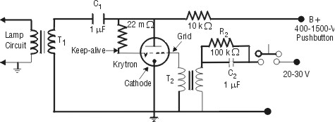
Fig. 11 (37) When arc lamps are used to pump lasers, it is more common to use other methods than overvoltage to initiate the discharge, so that the bias voltage V is lower than the breakdown voltage of the lamp. The middle portion of Figure 11 shows series triggering, also called series injection triggering. This method uses an "in-line" transformer. The transformer is wound with heavy-gauge wire for its secondary, which is connected in series with the lamp in the main discharge circuit. When a pulsed voltage is applied to the primary of the transformer, the voltage in the secondary exceeds the breakdown voltage of the lamp and the discharge begins. This triggering method is the most common one for initiating the discharge in arc lamps used with continuous solid-state lasers. It has the highest reliability, especially with high-pressure krypton arc lamps, because the triggering occurs at lower bias voltage V. (38) The external trigger method, shown in the bottom portion of Figure 11, employs a high-voltage pulse, perhaps 15 kV, which passes through the trigger wire that is wrapped around the outside of the arc lamp. The presence of the high voltage will induce some ionization in the lamp, enough to start the discharge. External triggering has the desirable features of using less-expensive transformers than are used with series triggering and of removing the secondary wiring of the transformer from the main discharge circuit. But it has disadvantages of exposing high voltage on the outside of the arc lamp and of generating more electromagnetic interference (EMI). Thus it is used less often than series triggering. (39) The circuit in Figure 10 showed use of a silicon-controlled rectifier in the trigger circuit. Figure 12 shows an alternate method for generating the trigger pulse. It uses a tube called a krytron, filled with krypton gas. The fourth electrode in this tube maintains standby ionization in the krytron to make triggering easier. The capacitor C1 is charged to 1000 V through the resistor R1, while the capacitor C2 remains initially uncharged because of the resistor R2. When the push-button switch is closed, C2 charges through the primary of transformer T2. This applies a voltage pulse of 300-500 V to the grid of the tube. The grid-to-cathode voltage is sufficient to ionize the gas, allowing current to flow from the anode to the cathode. The capacitor C1 discharges rapidly through the primary of T1, producing a pulse around 20 kV in the secondary of T1. This type of circuit is sometimes called a crowbar, because it has the same effect as dropping a crowbar across the terminals of the capacitor C1 and transformer T1.
Fig. 12 (40) The initial trigger pulse carries the arc lamp past the breakdown point but does not lower the flashtube resistance to the point where the main power supply will sustain the discharge. The function of the starting power supply is to drive the discharge through its period of arc expansion during lamp start-up, into the regime where the main power supply can take over and operate the lamp continuously. The starting power supply essentially lowers lamp resistance to the point where the lower-voltage main power supply can operate the lamp. In Figure 10, this function is performed by a starting power supply with relatively low current capability and by the capacitor C1. The starting power supply charges C1, which then discharges after the lamp is triggered and provides the required current pulse to drive the arc through its expansion phase. (41) The starting power supply is sometimes called a boost power supply. In some cases, two stages of starting power supply are used. Under some circumstances, especially if gas pressure in the arc lamp is relatively low, the starting power supply may not be necessary. (42) The main power supply should be a well-regulated current-controlled power supply, with relatively little ripple, capable of supplying the current and voltage to drive the lamp continuously in its regime of wall-stabilized operation. Its function is to supply the necessary current to maintain the electrical discharge after start-up. This is the region in which the arc lamp spends its useful life.
Mechanical Characteristics (43) This section will describe some of the important considerations related to lamp construction, lamp envelopes, electrode configurations, and mounting techniques. (44) Just as in flashlamps, the envelope for continuous arc lamps for laser pumping applications is usually fused quartz (vitreous silica). It is used for the same reasons it is employed in flashlamps, including its transmission over a broad spectral range (from the mid-infrared well into the ultraviolet), its high thermal conductivity, and its relatively low thermal expansion coefficient. These last two properties are very desirable in the environment of high thermal loading that is characteristic of laser pumping. Glass has been used as the envelope for lamps for applications requiring lower average power, but glass cannot withstand the severe thermal environment and high energy-dissipation requirements associated with pumping of continuous solid-state lasers. (45) There are three basic structural variations for sealing the electrodes into the quartz tubes for continuous arc lamps:
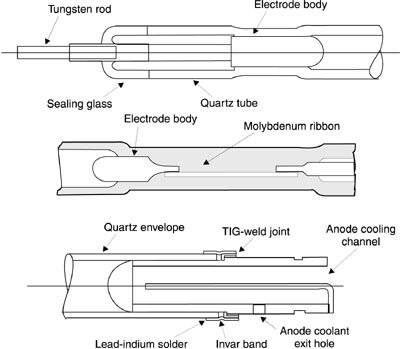
(46) The first and third of these sealing methods are similar to those described in connection with sealing of flashlamps, but the ribbon seal is not used in flashlamps. (47) Rod- or graded-seal lamps have a thin tungsten rod welded or brazed to the electrode. Then the seal between the tungsten and the quartz envelope of the lamp is made with one or two glasses that have values of the coefficient of thermal expansion intermediate to the values of tungsten and quartz. The rod-seal construction is shown in the top portion of Figure 13. This arrangement allows the stress arising from thermal expansion to be reduced at any particular material interface. In turn, this allows the lamps to be processed at high temperature in vacuum, to reduce contamination. It also allows operation of the lamps at high temperature. Rod-seal arc lamps are capable of reliable operation at relatively high operating temperature. They are frequently chosen for use in pumping solid-state lasers because of their relatively long life, their ability to operate with high electrical currents, and their ability to handle high average power.
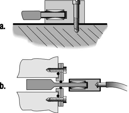
Fig. 13 (48) Ribbon-seal arc lamps use a molybdenum ribbon to make the seal to the quartz tube. The structure of such a seal is shown in the middle portion of Figure 13. This structure is formed in a high-temperature vacuum process, like the rod seal. The ribbon seal thus also produces lamps with very low contamination. (49) As compared to the other types of seal, the thick section of quartz around the molybdenum ribbon provides a high degree of ruggedness. But the ribbon seal cannot handle currents as high as the rod seal can. Thus its use is restricted to applications in which current can be held to moderate values. (50) Solder seals, also called end-cap seals, incorporate a seal between a circular band of invar (a nickel alloy with low thermal expansion coefficient) and the quartz tube. The circular band constitutes the end cap, as shown in the bottom portion of Figure 13. The seal is made with a lead-indium solder with a melting point around 350° C. Perhaps the main motivation for use of the solder seal is lowered manufacturing cost. The structure is also compatible with incorporation of cooling channels directly into the anode assembly, so that end caps are often used in larger-diameter arc lamps, for which cooling of the anode becomes a problem. But because of the relatively low melting point of the solder, the seals cannot be processed at high temperature, in contrast to the rod and ribbon seals. As a result, the solder seals may have shorter lifetime and poorer reliability. They are also restricted to operation at moderate currents, because they cannot tolerate the heating associated with high-current operation. (51) Electrodes in arc lamps must withstand high temperature and high electrical current density over hundreds of hours of operation. The tips of the anodes are generally either pure tungsten or thoriated tungsten. Thoriated tungsten is tungsten impregnated with thorium oxide. It has superior machining characteristics to tungsten. The cathode tip is usually formed of a so-called tungsten dispenser matrix, although sometimes thoriated tungsten is used. The dispenser matrix is tungsten impregnated with an emission material that lowers the work function of the surface and allows it to emit more electrons at a given temperature. Each manufacturer has its own proprietary materials for the dispenser matrix. (52) Shape of the cathode is one of the distinguishing features between flashlamps and arc lamps. Tips of the anodes in arc lamps are rounded, similar to the shape of anodes in flashlamps. This allows spreading of the anode current over a larger area. But the tips of the cathodes in arc lamps are pointed. This allows the discharge to attach to a single point at the cathode and helps position the arc in the center of the bore. This is in contrast to the case of flashlamps, in which the cathode tips are rounded. Because of the higher values of peak current the flashlamp must carry, a pointed tip would be eroded rapidly. (53) Conventionally, many manufacturers mark the anode end of their arc lamps red. (54) Mountings and supports for arc lamps are another important consideration. The end mountings often serve both as the physical support for the arc lamp and as the electrical connection. There are many possible variations for end mountings. It is extremely important that the mountings be secure, but not exert stress on the lamp seal or housing. The seals of arc lamps are susceptible to failure when they are stressed, especially when they are stressed in a direction perpendicular to the long axis of the tube. The support must be flexible, yet firm enough to support the lamp well and to form a good electrical contact capable of carrying high values of electrical current. (55) The common mounting methods are also similar to those used with flashlamps. (56) Two approaches, out of many possible, are shown in Figure 14. The top portion of the figure shows a mount that employs a louver band made of a springy metal, like beryllium-copper. The louver band flexibly supports the lamp by its base. The design can handle high current density. It is compatible with designs in which the cooling water is allowed to contact the electrical connections.
Fig. 14 (57) The lower portion of Figure 14 shows a design that avoids contact between the electrical connections and the cooling water. It makes use of O-rings. Possible problems may arise because of high temperatures reached by the end terminals, which are not cooled by the water. These problems become more severe as tube diameter increases; for bore diameter greater than 5 mm, it is necessary to have some contact of the cooling water with the end terminal. (58) Some laser manufacturers have developed mounting fixtures that allow the arc lamp to be removed and replaced without opening the laser cavity. The lamps are removed through the end of the laser pump housing assembly.
Cooling for Arc Lamps (59) Because of the very high power dissipation by arc lamps, they must be effectively cooled. Total power dissipation may be in the multikilowatt range (see Table 1) and power denisty dissipated at the surface of the envelope may exceed 300 W/cm2. If temperature of the lamp is allowed to increase excessively, the lamp may fracture because of overheating or stress buildup. Even if this does not occur, life of the lamp may be significantly decreased because of electrode deterioration. Thus, effective cooling is needed to keep the electrodes, seals, and envelope at acceptable temperatures. (60) The only way to cool an arc lamp adequately is with a liquid flowing with high velocity along the outside of the envelope. This is in contrast to the case of flashlamps operating at lower average power dissipation, which may be cooled adequately by flowing gas. In practice the coolant used is water, although other coolants have been investigated. The water must have high purity, both to reduce electrical shorting problems and to avoid buildup of dark deposits on the surface of the lamp. Deionized water is generally used. (61) The design of an arc lamp is often in the form of a double-walled tube. The gas fill is in the inner tube. The outer jacket, coaxial with the inner tube, is filled with flowing cooling water. (62) The cooling water flowing along the surface of the lamp must be in close contact with the entire envelope of the lamp and it must be in turbulent flow. If any regions of boiling water develop along the surface of the lamp, the result is generally envelope fracture and explosive lamp failure. The flow velocity should be at least six meters/second. (63) In addition, the anode of an arc lamp may need special cooling. Many arc lamps, especially those with larger-diameter bores, have special cooling channels through the anode, and a fraction (perhaps 20%) of the cooling water flows through the anode. Cooling of the cathode is less critical and special cooling channels are not usually employed.
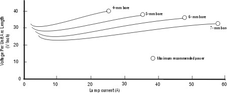
Arc-Lamp Failure Mechanisms and Lifetime (64) A number of factors contributes to gradual degradation of the light output of continuous arc lamps, leading eventually to their failure as an effective light source for the excitation of lasers. (65) The leading causes for normal arc-lamp degradation over a period of several hundred hours include:
(66) Cathode degradation is perhaps the leading cause of arc-lamp deterioration, because of darkening of the envelope and reduction of light output. When the lamp is at temperature, some of the impregnating chemicals in the dispenser cathode are driven out of the cathode and appear as white deposits on the inside wall of the lamp. These materials initially do not seriously reduce the lamp output. But as the lamp ages, the materials interact with the envelope and cause it to darken. (67) Deposition of metal from the electrodes also causes darkening of the envelope. Because operating temperature of the anode in an arc lamp is greater than in a flashtube, anode sputtering is greater in arc lamps. Sputtering from the anode is usually confined to a relatively small region near the position of the anode. (68) Gradual deterioration of the quartz envelope in a krypton arc lamp is related to electrode degradation and sputtering. The degradation takes the form of vaporization of the inside surface of the envelope and devitrification of the envelope. (69) Contamination of the fill gas in arc lamps can also influence the life. This results from causes such as outgassing of electrodes and evaporation of the envelope material. Contamination of the fill gas makes it difficult to trigger and start the lamps. (70) Typical lifetimes for arc lamps used for pumping lasers tend to be a few hundred
hours, ranging perhaps from 50 to 1000 hours, depending on the particular lamp and on the
power loading. As might be expected, the lifetime of an arc lamp is reduced as power
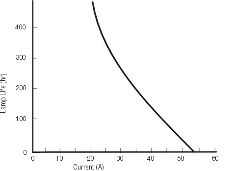
loading increases. Figure 15 shows lamp lifetime—defined as the time during which the
lamp output exceeds
Fig. 15 (71) At its rated current around 35 A, nominal lamp life would be 200 hours. But if current is increased to 50 A, lamp life drops to 50 hours. One could extend the lamp life by operating at a lower current than 35 A, but this would be at the expense of light output and reduced laser power. (72) The discussion above centered on mechanisms that cause the lamp to deteriorate gradually over a period of some hundreds of hours, with eventual failure caused by reduced light output or difficult starting. This should be considered the normal end of life for an arc lamp. But arc lamps may fail suddenly and catastrophically in several ways. This should not be considered the norm, but it must be mentioned as a possibility. Arc lamps are especially susceptible to stresses caused by bending or twisting the seals or to chipping of the envelope. Any loss of contact of the cooling liquid with the envelope is likely to cause envelope fracture and explosion. Driving the lamps above their recommended maximum operation points similarly can lead to explosive failure. To avoid these possibilities, the lamps must be handled and operated with great care. We shall discuss the care of arc lamps in detail in the next section. (73) Replacement of arc lamps at the end of their lifetimes is a significant expense for users of continuous solid-state lasers. The makers of arc lamps are seeking methods and materials to provide longer lamp life: hot tungsten cathodes and the use of molybdenum end caps. These expedients have led to extended life for experimental devices. We may expect that further developments will increase the operating life of arc lamps.
Arc-Lamp Maintenance and Care (74) To maximize the operating life of arc lamps and to reduce the cost of lamp replacement, proper maintenance and care are necessary. (75) Arc lamps are very sensitive to mechanical stress exerted around the lamp seals, particularly to bending stress. They should be handled with great care. When installing arc lamps, one should be careful not to stress the seals or the envelope. When the lamps are being mounted in clip holders, the clips may be expanded with a pencil eraser to allow easy, stress-free insertion. The clip holders should be inspected first to make sure that they are not corroded or bent. (76) Similarly, because of the lamps’ sensitivity to chips or scratches on the envelope, one should use great care in handling, making sure not to bump the lamp envelope into any objects. (77) The quartz envelopes are sensitive to contamination by fingerprints, dirt, or other contaminants. Surface contamination also reduces lamp life. Thus, one should not touch the lamp surface with bare hands. Arc lamps may be cleaned of fingerprint oil or other contaminants by careful wiping with lint-free tissue soaked in methyl alcohol. (78) Lamps should be inspected periodically for buildup of deposits on the lamp surface. If deposits are found, the cooling-system filter, deionizer cartridge, and deionized water should be changed. (79) One should, as much as possible, avoid thermal cycling of the arc lamps. One should start the lamps as seldom as possible. It is usually preferable to run the lamp continuously, rather than to shut it off for short periods. One should employ power supplies in which there are no large excursions in output and that have little ripple. (80) In summary, to maximize lifetime of arc lamps and reduce danger of explosion of the lamps, one should:
Safety Around Arc Lamps (81) Use of arc lamps is accompanied by several different types of hazards, and appropriate safety measures are required. Perhaps the most significant hazard is that of explosion. Arc lamps are filled with gas at a pressure above one atmosphere, and during operation the pressure rises, to as much as tens of atmospheres. Explosion should not be considered to be the normal end of life for arc lamps, but if there any nicks or scratches on the envelope, the lamp may explode during operation. Also, if the electrode seals have been stressed, they may fail during operation, with resultant explosion. In addition, if there is a loss of contact at any point between the cooling fluid and the lamp envelope, the lamp will overheat in that area and explode. The explosion will send fragments of glass flying in all directions and is a serious hazard to personnel. (82) Arc lamps also can explode during handling. This should not occur if the lamps are handled properly, but if the envelope is scratched or nicked, or if the end seals are subjected to mechanical stress, the lamp may explode. (83) Krypton arc lamps also can generate potentially harmful ultraviolet radiation. This may cause burns to exposed skin or, especially, to the eyes. One should not expose the skin or eyes to the directed or reflected radiation of an operating arc lamp. (84) Safety measures necessary to counter the explosion hazard include the following:

Continuous Nd:YAG laser pumped by krypton arc lamps (Quantronix Model 114 or equivalent) Krypton arc lamps (make and model appropriate for available laser) Plastic gloves Lint-free tissue and methyl alcohol DC ammeter DC voltmeter Laser power meter capable of operation at 1.06 m m Oscilloscope and low-capacitance probe Resistor, electrical leads, and connectors, as required 
In these procedures you will:
(85) In the first portion of the exercise, you will remove the arc lamps from the cavity of the laser, inspect them, clean them, and reinstall them. Procedures for arc-lamp removal vary from one laser manufacturer to another. For specific removal instructions, follow the procedures in the operator’s manual for the laser available. (86) The essential point for this portion of the exercise is to demonstrate a high degree of care in the handling of the arc lamps, avoiding any mechanical stress to the lamps in any part of the operation. (87) Wearing plastic gloves, remove the arc lamps from the laser cavity, following the manufacturer’s instructions. Carefully inspect the lamps for dirt or contamination. Inspect the lamp mounts for corrosion, contamination, or bending. Clean the surface of the lamps carefully, using lint-free tissue and methyl alcohol. Reinstall the lamps, taking great care not to stress the seals or the lamp envelope. (88) In the next portion of the exercise, you will demonstrate the procedures for starting arc lamps. Procedures given here are relevant to the circuit shown in Figure 10. If the circuit in the particular apparatus available is different from the one in Figure 10, the procedures may be adjusted accordingly. Values of the currents and voltages also should be adjusted to be in accordance with recommendations of the equipment manufacturer. (89) Adjust the voltage of the main power supply to the proper value for the specific arc lamp, typically around 200 V. The lamp is not drawing current. Starting power-supply voltage is raised to 1000 V or above to charge the starting capacitor C1. The B+ trigger voltage is increased to 1000-1500 V. The lamp is then triggered, usually with a manual push-button. The trigger circuit initiates the discharge, and the discharge of the starting capacitor lowers the resistance of the lamp. When voltage across the lamp drops below 200 V, the starting diode begins to conduct and the lamp will draw current from the main power supply. The value of the variable ballast resistor is adjusted so that the lamp is drawing the proper current. One adjusts this constant current supply to the desired value. Then the starting power supply and the trigger circuit are disconnected from the circuit. The same procedures are followed every time the lamp is started. (90) In the next portion of the exercise, you will measure the current/voltage characteristics of the arc lamps and will measure how output of the laser varies with lamp current. (91) Add a DC voltmeter and DC ammeter to the circuit as illustrated in Figure 16. Also, direct the output from the laser into the entrance aperture of the power meter. Start the lamps as was done previously. When the lamps are started, vary the voltage from the main power supply, starting from a minimum value necessary to sustain lamp operation. Increase lamp voltage in equal steps until the maximum recommended operating point is reached. At each step, record the lamp voltage, current, and laser power output. Plot lamp current as a function of lamp voltage. Plot laser output as a function of lamp current.
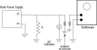
Fig. 16 (92) In the final portion of the exercise, you will measure the ripple of the main power supply for the lamps. This is important because low power-supply ripple is desirable for maximum lamp life. Every DC power supply, no matter how well regulated, will have some ripple, which may be observed as a waveform on an oscilloscope. (93) Connect the equipment as shown in Figure 17. The resistor R should have a value, in ohms, equal to the rated output voltage of the power supply divided by the maximum rated current.
Fig. 17 (94) Set the oscilloscope to its AC mode of operation. This eliminates the DC component of the power-supply output. Since ripple voltage is generally small compared to the DC voltage, the DC voltage would drive the display off the screen if one attempted to make a sensitive measurement in the DC mode of operation. Do not turn on the oscilloscope, until after the power supply is turned on. (95) Turn on the power supply. Measure the value of the voltage on the DC voltmeter. Adjust the oscilloscope controls to produce two or three stationary cycles of each wave on the screen. Measure the peak amplitude of the ripple on the voltage-calibrated vertical scale of the oscilloscope. (96) Calculate the percentage of ripple, using the equation: Ripple percentage = 100 ´ Ripple voltage/DC voltage.

1. Prepare a drawing showing the basic components of an arc-lamp power supply. Identify the function of each component. 2. Explain the purpose and operation of the trigger circuit for a continuous arc lamp. 3. Prepare a drawing showing the difference in construction between arc lamps and flashlamps. Identify the difference, and explain why they are made differently. 4. Identify different types of arc lamps, and list an application for each type. 5. Explain the failure mechanisms for arc lamps. Explain the effect of operation above rated current on lamp lifetime. 6. Describe safety measures that should be employed when one is working with arc lamps. 
Koechner, W. Solid-State Laser Engineering. 3rd ed. Berlin and New York: Springer-Verlag, 1992. Lenk, J. D. Complete Guide to Electronic Power Supplies. Englewood Cliffs, NJ: Prentice Hall, 1990. An Overview of Flashlamps and CW Arc Lamps. Technical Bulletin 3. Sunnyvale, CA: ILC Technology, 1986. Reichert, T., et. al. "Continuous-Wave Laser Pump Light Sources: New Concepts." Applied Optics 32 (1993): 6607-6609. Yoshikawa, S., K. Iwamoto, and K. Washio. "Efficient Arc Lamps for Optical Pumping of Neodymium Lasers." Applied Optics 10 (1971): 1620-23.
|
|||||||||||||||||||||||||||||||||||||||||||||||||||||||||||||||||||||||||