| This version reflects the comments of the core participants as reviewed and incorporated in accordance with CORD's FIPSE-supported Curriculum Morphing Project. | |
MODULE 4-2 Changes in red were made as a group by Jack Ready (Course Director), Cal Christensen, John Simcik (Texas State Technical College-Waco), and Ray Wick The power supplies for continuous-wave gas lasers are similar in design to those used in direct-current power supplies. Gas laser power supplies tend to be current-limited regulated DC power supplies. The designs are basically the same for all gas-discharge devices. The details depend on the particular voltage-current characteristics of the gas and the configuration of the laser. Three essential elements are used in the design of all gas laser power supplies: the starter or ignition circuit, the operating supply, and a current-limiting element. Many gas lasers such as CO2, metal vapor, and excimer are operated in a pulsed mode. These lasers pose greater problems in power-supply design because the impedance of the gas is changing rapidly during the laser pulse. 
When you complete this unit, you will be able to: 1. Draw a voltage/current curve for a gas laser tube. Indicate regions on the curve for pre-breakdown current, breakdown voltage, and discharge current. 2. Identify the three major elements of high-voltage power supplies used in gas lasers and explain the function of each. 3. Draw and label a voltage-doubler power supply for a helium-neon laser with an internal starter circuit. Include approximate values for the components. Show current charge paths for capacitors and trace current from load back to power supply. 4. Explain the operation of a thyratron tube. 5. Describe the operation of pulsed carbon dioxide TEA lasers. 6. Draw and label a typical circuit for a CO2 TEA laser power supply. 7. Draw and label a typical high-voltage delivery circuit for an excimer laser. 8. Draw and label a Marx bank power supply circuit and explain its operation. 9. Using parts and schematic diagram provided, assemble a power supply for a helium-neon laser tube. Use the power supply to operate the laser tube. 10. Measure the tube voltage and current during operation of a helium-neon laser tube. Plot the current/voltage characteristics and determine the breakdown voltage and the region of negative resistance for the tube.
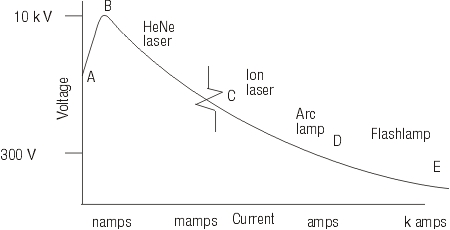
Electrical Characteristics of Most gas lasers are pumped by an electrical discharge that flows through the gas mixture between electrodes in the gas. Collisions between electrons in the electric discharge and the molecules in the gas transfer energy from the electrons to the energy levels of the molecule. In this process, the upper levels of the laser transition become populated. To describe the requirements of the power supplies needed to drive the gas discharges, we begin with a discussion of the nature of the discharge and its initiation. Electrical discharges in gases are characterized by current/voltage characteristics shown in Figure 1. The exact characteristics, of course, depend on the nature of the gas, its pressure, and the length and diameter of the discharge. At low values of voltage applied to the gas, there is no current flow. As the voltage is increased, the current remains essentially zero until some relatively high voltage is reached. This is denoted point A in the figure. At this point a very small current begins to flow because of a small amount of ionization that is always present. This small amount of ionization is provided by the presence of natural radioactivity and cosmic rays. The small current is referred to as the pre-breakdown current. The value of the current in this region may be a few nanooamperes.
Fig. 1 The pre-breakdown current increases slowly until a point called the breakdown voltage (perhaps around 10kv) is reached (point B in the figure). This is the value at which a large number of gas molecules becomes ionized. The conductivity of the gas is increased and the electrons are accelerated to velocities at which they can transfer enough energy to ionize more molecules through collisions. Thus as the current increases, the resistance of the gas decreases and the voltage required to sustain the discharge actually decreases with increasing current (region C in the figure). This is a condition called negative resistance. It is the behavior that would be predicted by Ohm’s law with a value of resistance less than zero. The current would continue to increase, through region D (amperes) to thousands of amperes (region E), with less and less voltage required to sustain it. Eventually some catastrophic event would occur. Thus, the current must be limited by inserting a positive resistance in the circuit. This positive resistance, called a ballast resistor, has the effect of limiting the current and keeping it within acceptable bounds. Figure 1 shows ranges of current, from nanoamperes to kiloamperes, along the abscissa. Devices operating at various valves of current are indicated above the curve. The requirements for power supplies for gas lasers derive from the characteristics of the curve in Figure 1. The exact design for a particular gas laser power supply will depend on the specific current/voltage curve for the gas mixture that is being excited, but three essential elements for any gas laser power supply are:
The characteristics of the gas discharge as shown in Figure 1 lead to challenges in the design of power supplies to drive gas lasers. It becomes difficult to control the voltage across the gas because after the discharge begins, the voltage depends on the current. To maintain a specified voltage across the gas, one controls the current to the value that corresponds to the desired voltage. In pulsed lasers, the impedance of the gas is changing over a very large range. As the gas breaks down and begins to conduct, the impedance drops rapidly. This makes the design of power supplies difficult. It becomes hard to control the current rapidly enough. We now turn to a description of power supply requirements for several types of gas lasers, beginning with the common He-Ne laser, and also describing power supplies for carbon dioxide lasers, metal vapor lasers and excimer lasers. The discussion of power supplies for ion lasers will be in the next module.
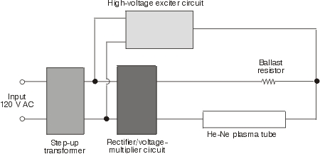
Power Supplies for Helium-Neon Lasers The helium-neon laser uses a mixture of helium and neon gases at a pressure in the range from a few tenths of a torr to a few torr. The exact pressure depends on the diameter of the laser tube. Although the actual laser emission arises from the neon atoms, the gas mixture typically contains five to ten times more helium than neon. The excitation of the neon atoms to the upper laser level is derived from an electrical discharge. In steady operation, the discharge passes a few milliamperes of current through the gas at a voltage in the range 1-2 kilovolts. Electrons in the discharge collide with the helium and neon atoms and raise them to excited energy levels. Most of the excitation is received by the more abundant helium atoms, which easily can transfer their excitation energy to neon atoms. This produces in the neon a condition of population inversion, in which a higher-lying energy level is more heavily populated than a lower-lying level. The condition of a population inversion is necessary for laser operation to occur. In the laser emission, the neon atoms fall from the higher energy level to the lower level, and emit the energy difference as laser light. The most common wavelength of emission is 632.8 nm, but a variety of other wavelengths is possible. In steady operation, the power supply must sustain the flow of electrical current through the gas mixture, accelerating free electrons to energies sufficient for excitation of the helium atoms and providing enough current flow to produce an adequate population inversion. The basic blocks of the power supply for a typical small helium-neon laser are shown in Figure 2. The input voltage first is increased by a transformer. The high-voltage exciter circuit supplies a voltage pulse that breaks down the gas and initiates the electrical discharge through it. The rectifier circuit converts alternating current to direct current and provides the necessary direct current for continuous steady-state operation. This portion of the circuitry often includes a voltage multiplier that increases the voltage from the transformer still further. The ballast resistor limits the current through the tube to a safe value.
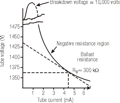
Fig. 2 The characteristics of the power supply for the helium-neon laser derive from the properties of the current/voltage curve for the helium-neon gas mixture. We already have discussed the general properties of current/voltage curves with respect to Figure 1. Figure 3 shows the current/voltage curve specific to a helium-neon mixture. The numerical values are typical for a low-power (few milliwatt) device. The breakdown voltage is around 3400 volts. At applied voltages below this value, very small values of current flow through the tube. When the breakdown voltage is applied, some of the neon atoms become ionized. A neon plasma is produced. This leads to a large increase in the current.
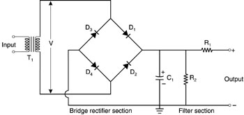
Fig. 3 We should note that the gas in the tube is weakly ionized; only a small fraction of the neon atoms become ionized. To supply the breakdown voltage momentarily to cause the initial ionization, a high-voltage exciter circuit or starter circuit is needed. This sometimes is called the voltage kicker or igniter circuit. In practice, the starter circuit often is integrated with the rectifier circuit. We will describe the details of the starter circuit shortly. Returning to Figure 3, in the region to the right of the breakdown point, it takes much less voltage across the tube after ignition to sustain a stable discharge. The DC voltage required in this region, which is the normal operating region for the laser, is supplied by the rectifier/voltage-multiplier section of Figure 2. Another important feature of the current/voltage curve is that it behaves as if the resistance of the discharge were negative. According to Ohm’s law for conventional resistors, to increase current flow, the voltage across the resistor must increase. But in the discharge tube for a helium-neon laser, a decrease in tube voltage leads to an increase in tube current. This is interpreted conventionally as an Ohm’s law type of relationship in which the resistance is negative. This interpretation is consistent with the negative slope for the current/voltage curve to the right of the breakdown voltage. Because increasing current requires less voltage, the current can continue to increase with no limitations imposed by the plasma. If the current were not limited in some other way, it could increase to a very large value, large enough to damage the tube. Thus a ballast resistor, a conventional resistor with a positive value of resistance, is inserted in series with the rectifier/voltage-multiplier circuit. This limits the current flow to a safe value. For the current/voltage curve shown here, to limit the operating current to a value around 4.5 mA, which we shall see later is an appropriate value, the value of the ballast resistor would be about 300 kW . We now discuss some details of circuits that have been used for driving helium-neon lasers. A number of different configurations has been used by different manufacturers. We shall not attempt to describe them all, but shall choose some representative examples. An example of one operating supply is the rectifier bridge shown in Figure 4. This is a full-wave bridge rectifier with an RC filter to smooth out fluctuations in the applied voltage. The term full-wave means that both the positive and negative alterations of the alternative current cycle are used, as opposed to a half-wave supply, in which only one of the alterations is used. The full-wave bridge requires more components than the half-wave supply, but the discharge time for the capacitor C2 is shorter than for half-wave rectification. Thus, the full-wave supply has less ripple than a half-wave supply.
Fig. 4 T1: 120 to 3000 V In the full-wave bridge, when the upper end of the transformer T1 is positive, current flows through diodes D1 and D4. This charges capacitor C1 to the peak value V of the voltage of the transformer. When the lower end of T1 is positive, current flows through diodes D2 and D3. This also charges C1 to the voltage V. The resistor R1 is the ballast resistor, but it also acts as an element in the RC filter. The value of R1 may be varied to adjust the tube current to the desired value. The bleeder resistor R2 allows charge to drain from C1 when the power supply is turned off. The values given for the components are typical for operation of a helium-neon laser with a tube length around 40 cm. For the values given, the time constant of the filter circuit would be about 0.1 sec, a time much longer than the period of the line voltage at the transformer primary terminals. Thus the voltage output will be relatively constant, with little ripple. A different possibility for the operating supply is shown in Figure 5. This combines the rectifier circuit with a voltage-doubler circuit. This is the type of functionality shown in Figure 2, which illustrated combined rectifier and voltage-multiplier functions. This type of circuitry allows the input voltage to be increased more easily to the high values needed for operation of the laser. It allows the use of a lower-voltage transformer and lower-voltage diodes. The figure also indicates the current flow at two positions.
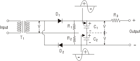
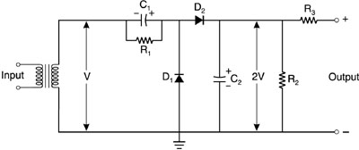
Fig. 5 T1: 120-700 V In this circuit, when the top of T1 is positive, the capacitor C1 is charged by current flowing through diode D1. When the bottom of T1 is positive, C2 is charged by current flowing through D2. The capacitors are in series, so the DC voltages add to give a doubled output voltage. The resistors R1 and R2 are bleeder resistors. The resistor R3 is the ballast resistor and also acts as a filter element. The value of R3, or the input voltage, may be varied to give the proper current through the tube. The component values specified would be appropriate for a tube with a discharge about 35 cm long. Another possible voltage-doubler circuit is shown in Figure 6. When the bottom of T1 is positive, current flows through D1 and charges C1 to voltage V. When the top of T1 is positive, its voltage and the voltage of C1 add in series. Current then flows through D2 so that C2 is charged to voltage 2V. The resistors R1 and R2 are bleeder resistors and R3 combines the functions of ballast resistor and filter element.
Fig. 6 T1: 120-700 V
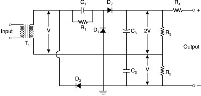
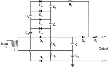
A voltage-tripler circuit is shown in Figure 7. The circuit is basically a combination of the two shown in Figures 5 and 6. The voltage on C3 will be 2V, while that on C2 will be V. The output voltage is then 3V. The reason for use of this type circuit is to be able to use the same transformer in different models of helium-neon lasers. One may obtain different values of voltage with a single model of transformer. This may make the purchase of the transformers more economical.
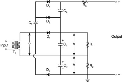
Fig. 7 T1: 120-700 V We now turn to the starter circuits used to trigger the electrical discharge through the gas. One simple type of starter uses an external trigger pulse in conjunction with a full-wave bridge rectifier circuit. A wire from one side of the transformer is connected to an external electrode on the tube. The external electrode is located near the cathode. The electrode may be a strip of metal foil wrapped around the tube. The peak voltage from the transformer is applied between the external electrode and the cathode. The resulting electric field is high enough to cause some ionization in the gas within the tube, so that the breakdown of the gas can begin. This type of starter cannot be used with other types of operating supplies because the output voltage from their transformer rectifiers is not high enough. Internal starting circuits are used more commonly. They also are more complicated than the external triggering arrangement. One type of internal starting circuit is shown in Figure 8. The starter is used with a voltage-doubler operating circuit as has been described. The first and second half cycles of the alternating input voltage charge capacitors C1 and C2 each to voltage V. The second half cycle also charges C3 to voltage 2V. Then, on the third half cycle, current flows from C3 and charges C4. At the end of the third half cycle, C3 and C4 are each charged to voltage V. The process continues on each successive cycle. The capacitor C3 is charged to 2V and then transfers some of its charge to C4 until both capacitors are charged to 2V. The voltages of all four capacitors add in series, so that the maximum output voltage would be 6V. The value 6V is greater than the breakdown voltage of the tube. At some point during the buildup of the output voltage, the breakdown voltage across the tube will be exceeded and the discharge will begin.
Fig. 8 T1: 120-700 V When the discharge begins, the resistance of the tube drops substantially. The voltage 2V across C1 and C2 is enough to maintain the tube current. The diodes D3 and D4 conduct this current, and C3 and C4 are bypassed. The capacitors C3 and C4 in the starting circuit have small values, typically a few thousandths of a microfarad. Their function is to deliver the single pulse of high voltage needed to break down the gas in the tube. Another possible variation of a voltage doubler with an internal starter circuit is shown in Figure 9. The most important change from the circuit in Figure 8 is the addition of a diode and a resistor that make it unnecessary for the operating current to flow through all the diodes. The figure shows four diode-capacitor pairs in the starting circuit. This allows the attainment of even higher starting voltage. The number of diode-capacitor pairs will depend on the particular laser tube and its breakdown characteristics.
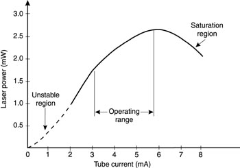
Fig. 9 T1: 120-700 V D1,2: 2000 PIV, 25 A D3–7: 2500 PIV, 25 A C1,2: 2 m F, 1200 V DC C3-6: 0.005 m F, 2000 V DC R1,2: 1 MW , 1 W R3: 120 kW , 12 W R4: 4 MW , 0.5 W When the tube is triggered and the discharge is passing through the gas, the output power of the laser may be varied by varying the current through the tube. This frequently is done by employing a variable ballast resistor and adjusting its resistance to optimize the light output. Figure 10 shows how the output power varies as a function of tube current for a small helium-neon laser. The results are for a laser tube with internal diameter of 1 mm and length 30 cm. At low values of current, less than 2 milliamperes or so, the discharge is unstable. The light emitted by the discharge flickers and only very little or no laser output is observed. As the current rises above 2 milliamperes, the discharge becomes stable. The flickering ceases and usable laser output appears. For this particular device, the usual operating range would be from 3 to 5.7 milliamperes, with laser output in the range from 1.8 to 2.6 milliwatts.
Fig. 10 As the current increases further, above 5.7 milliamperes, the output power begins to drop. (This occurs because the increased current heats the gas excessively.) This is an undesirable situation. It causes a decrease in the population inversion and also can shorten the life of the laser tube. Hence, one should limit the current to a value no higher than the value corresponding to the peak on the light output curve. This value of current, above which the light output starts to decrease, is called the saturation current. The saturation current will vary from one device to another, depending on tube diameter, discharge length, and gas pressure. Many commercial helium-neon lasers use currents around 5 milliamperes, but higher values are used in some devices. The power supplies for helium-neon lasers are inherently simple. They have modest power requirements, with power consumption in the 20-watt range for output power around one milliwatt. Low-power helium-neon lasers usually have passive air cooling. Higher-power models may have forced-air cooling with fans. The input voltage for most helium-neon lasers is the standard 120-V AC wall plug. For some models a 230-V AC input option is available. The development of power supplies for helium-neon lasers is quite mature, and many standard models are available from many manufacturers.
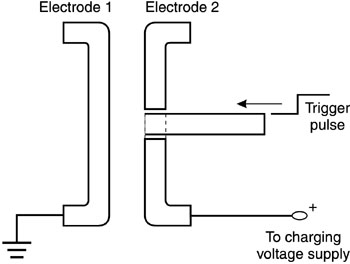
Switching Elements Helium-neon lasers almost always are operated continuously. After the startup, there is no need for high-voltage pulsing of the power supply. We now shall turn to a discussion of gas lasers that frequently are operated as pulsed lasers, and for which there is a need for short-duration high-voltage pulses. As a preliminary to the discussion of these lasers, we first shall describe high-voltage switching elements that often are employed with pulsed gas lasers. The two high-voltage switches that we will describe are spark gaps and thyratrons. These two types of switches commonly are used with gas lasers. In some cases other types of high-voltage switches have been employed, including solid-state switches. We later shall refer briefly to some of these in regard to specific lasers. The spark gap is a conceptually simple device. It consists of two electrodes separated by an insulating material. The insulating material may be a gas, solid, or liquid, but a gas is the most commonly used material. For our discussion, we will consider only gas-filled spark gaps. A voltage is applied across the spark gap, lower than the breakdown voltage for the gas. Then a trigger pulse is applied and the gas breaks down. The trigger often consists simply of applying a momentary overvoltage between the electrodes. Then the gas breaks down and current flows across the gap. The required breakdown voltage depends on the nature of the gas, its pressure, and the shape and separation of the electrodes. For plane electrodes spaced one centimeter apart and for a gas pressure of one atmosphere, the breakdown voltage is 1.3 kV for neon, 3.4 kV for argon, 12 kV for hydrogen, 22.8 kV for nitrogen, and 23 kV for air. These values are reduced for pointed electrodes. One possible electrode configuration for the electrodes in a spark gap is shown in Figure 11. Voltage is applied between the electrodes. When the trigger pulse arrives on the trigger electrode, the breakdown voltage across the gas is exceeded and the gas between the electrodes breaks down and becomes conductive. We should note that the spark gap could be employed in the opposite polarity also.
Fig. 11
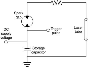
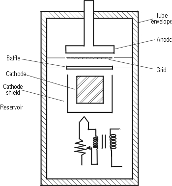
Fig. 12 Spark gaps usually are employed as high-voltage closing switches. A typical use to trigger a discharge in a pulsed gas laser tube is shown in Figure 12. The storage capacitor is charged to a voltage above the breakdown voltage of the laser tube, but the tube is isolated from the spark gap. When the spark gap is triggered, the laser tube is in an overvoltage condition and breaks down. The energy-storage capacitor discharges through the tube, which then produces a pulse of laser light. The applied voltage must be removed from the spark gap for the gap to recover to its open state. The recovery time is dependent on the nature and pressure of the gas and on the geometry of the gap. It can be as long as milliseconds. For this reason, spark gaps usually are not used when high-pulse-repetition-rate pulsing is required. Thyratron tubes offer higher performance characteristics than spark gaps, but are also more expensive. A thyratron is a gas-filled multielement tube with a hot cathode. Thyratrons are fabricated with glass or ceramic tubes, metallic anodes, and one or more grids. The grid controls the start of a continuous current so that the tube has a trigger effect. They are filled with hydrogen or deuterium at low pressure. Thyratrons were often used in early laser models. They have largely been replaced by solid state switches which offer longer lifetime, but thyratrons may still be encountered in older lasers. Figure 13 shows a simplified typical internal structure for a thyratron. The anode is usually of copper or molybdenum and the cathode of tungsten, coated to increase its emission of electrons. The baffle located behind the grid shields the grid from stray electrons emitted by the cathode. The reservoir contains a material like titanium hydride (or deuteride). When the reservoir is heated it establishes an equilibrium vapor pressure of hydrogen. This is necessary because hydrogen is absorbed by the tube and the electrodes.
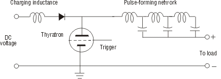
Fig. 13 Figure 14 shows how a thyratron could be used in a pulse-forming circuit. The conventional electronic symbol for a thyratron is indicated. When the tube is triggered by a positive trigger pulse, the gas in the tube breaks down and current flows through the tube. The circuit in the figure would be suitable for delivering a pulse of current to drive a gas laser.
Fig. 14 General Comments of John Simcik The circuit is intended as a pulse circuit and issues of matching the impedance of the load become important. The figure shows a pulse-forming network of capacitors and inductors in the discharge portion of the circuit. The current is limited by the inductance. The pulse-forming network is designed to optimize the efficiency of the circuit for energy deposition in the load. In addition, to provide resonant charging at high pulse-repetition rate, a charging inductance is inserted. After the tube has conducted and the current has fallen to zero, the electrons and ions in the thyratron should recombine rapidly and make the device electrically neutral. Then it is ready for another application of high voltage. Hydrogen-filled thyratrons have shorter recovery times than do deuterium-filled devices, but deuterium provides a higher standoff voltage. Thyratrons are capable of switching at rates greater than 20 kHz. They have very short jitter, perhaps 1-2 ns, as compared to the 20-ns jitter of spark gaps. Thus, thyratrons are preferred to spark gaps when very accurate pulse timing is desired. They are more expensive than spark gaps, however. Both thyratrons and spark gaps frequently are used for rapid switching of the power supplies associated with pulsed gas lasers.
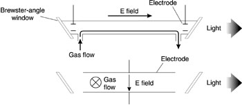
Carbon Dioxide Laser Power Supplies The carbon dioxide laser employs a mixture of carbon dioxide, nitrogen, and helium. The carbon dioxide is the active laser material. The upper laser levels of the carbon dioxide molecule are excited by collisions with excited nitrogen molecules, which in turn are excited by collisions with electrons in an electrical discharge through the gas mixture. The helium helps to depopulate the lower laser level by collisions and helps to remove heat. Carbon dioxide lasers most often operate continuously, but may be pulsed readily by pulsing the electrical power supply. In that case, the pulse has an initial spike followed by a longer, lower-power tail, at a power level close to that available in continuous operation. This pulse form is often useful for metalworking, with the initial spike breaking down the metal surface so that the energy in the tail can couple effectively into the metal. Early studies of carbon dioxide laser operation indicated that the power output scaled with the length of the laser tube. Typical power extraction was around 50-60 W/m of discharge length, for carbon dioxide lasers with relatively slow gas flow. Thus, continuous output power of a few hundred watts was easy to obtain in devices of reasonable size. But an output in the kilowatt range required an unreasonably long tube. In the late 1960s, it was discovered that increasing the rate of gas flow increased the output power. The power increased rapidly with gas-flow rate until it saturated at a flow near 4000 ft3/min. With fast gas flow, it is possible to obtain output powers of several hundreds of watts per meter of discharge length. It then becomes possible to construct lasers with high power (kilowatts) in devices of reasonable size. Thus the evolution of carbon dioxide laser construction has been as illustrated in Figure 15. The early models of carbon dioxide lasers were constructed as shown in the top portion of the figure, with gas flow along the axis of the tube sufficient to remove the harmful decomposition products. Such lasers now are referred to as slow axial-flow devices. A second class of lasers, with capability of higher power, uses fast flow of the gas along the length of the tube. Such devices are called fast axial-flow lasers. Such devices can emit perhaps 600 W/m of discharge length. Then models were developed in which the gas flow is perpendicular to the long axis of the laser, i.e., transverse to the optical path, as shown in the bottom portion of Figure 21. Because the impedance to gas flow is reduced with transverse flow, the power output can be increased further. Also the electrical discharge may be perpendicular to the optical path. It becomes easier to supply the optimum electric field (voltage per unit length) when the length of the discharge is reduced. Thus in many modern lasers, the electric field also is supplied perpendicular to the optical path. With a configuration such as shown on the bottom portion of the figure, extraction of several kilowatts of continuous power in a reasonably sized device becomes possible. Lasers constructed in this fashion are called transverse-flow lasers. Models of transverse-flow multikilowatt carbon dioxide lasers, with continuous power up to 45 kW, have become available. Models of slow axial-flow, fast axial-flow, and transverse-flow carbon dioxide lasers are all available commercially, with somewhat overlapping power ranges.
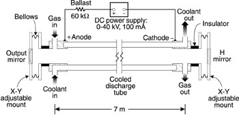
Fig. 15 The basic power supply for a continuous carbon dioxide laser operating at relatively modest power levels is relatively simple, consisting of a high-voltage power supply and a ballast resistor to limit the current. Figure 16 shows a schematic diagram of a continuous axial-flow carbon dioxide laser, with an assumed tube length of 7 meters. The provisions for gas flow and coolant flow are indicated. The current source may be simply a commercial high-voltage power supply, capable of operation up to several tens of kilovolts. Such a laser could be capable of operation at output levels of a few hundred watts. Many early carbon dioxide lasers operated with power supplies no more sophisticated than what is indicated in the figure.
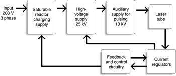
Fig. 16 In practice, power supplies for modern commercial carbon dioxide lasers become more complex. Figure 17 shows a block diagram for a commercial carbon dioxide laser capable of operation at the kilowatt level. The input power is 208 V, three-phase. The laser operates continuously with the 25-kilovolt supply. If the laser is to be operated in a pulsed mode, the extra 10-kilovolt power supply is activated, so that the voltage to the tube is increased to 35 kV. The charging of the power supply is controlled by a saturable reactor that will be described in more detail below. Variations in the discharge current are monitored and controlled by the feedback network. The control circuit compensates for variations by controlling the current to the saturable reactor.
Fig. 17
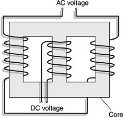
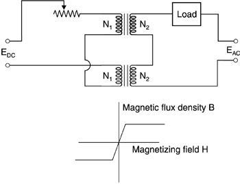
Fig. 18 One commonly employed device used in circuits designed for laser power supplies is a saturable reactor. A saturable reactor is a magnetic device that has nonlinear response to an input. Figure 18 shows a schematic diagram of the structure of a saturable reactor. The device has an iron-based three-leg magnetic core. It has a control winding that carries direct current. The value of the direct current is adjusted to change the degree of magnetic saturation of the core. This changes the reactance that the AC winding offers to the flow of a time-varying current. Figure 19 illustrates operation of a saturable reactor in a circuit. The top portion shows the configuration of the circuit and the bottom portion shows the magnetization curve for the device in an idealized fashion. In actual devices, the magnetization curve is a hysteresis loop with very small width. When the DC control voltage EDC is zero, the device is unsaturated. When the DC control voltage is greater than zero, current will flow through the control windings N1. The magnetic flux density in the core is increased. The time-varying magnetic flux density changes in response to the AC voltage EAC and the device will saturate as the AC current increases to some threshold value. The voltage across the load depends on the voltage across the load windings N2. As the AC voltage first increases from zero during its first half-cycle of the alternating current, this voltage appears almost entirely across the windings N2 before saturation. As the AC voltage continues to increase, the magnetization saturates and the flux density jumps abruptly to its maximum value as shown in the lower portion of the figure. When saturation occurs, the voltage across N2 drops to near zero and the voltage appears almost entirely across the load. As the AC voltage drops at the end of the half-cycle, the device unsaturates and the voltage again appears across the windings. The result is an essentially constant-current square-wave output to the load. The square wave has a duration equal to the time during which the device remains in magnetic saturation. Saturable reactors often are used as constant-current sources to drive laser power supplies.
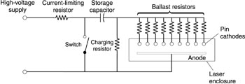
Fig. 19 So far we have discussed basic continuous carbon dioxide laser configurations. There have been many variations of carbon dioxide laser types. Within the scope of this module, we will describe only one, the so-called TEA laser. The power supplies for TEA lasers have features of special interest. A common variety of pulsed carbon dioxide laser is the TEA (transversely excited, atmospheric-pressure) laser. This is inherently a pulsed device rather than a continuous laser. In contrast to most carbon dioxide lasers that operate at total gas pressures much less than one atmosphere, the TEA laser operates near one atmosphere gas pressure. This allows extraction of relatively large amounts of energy per pulse. The energy in a pulse from a carbon dioxide laser that is pulsed in the microsecond regime increases as the square of the gas pressure. Thus it became desirable to increase the gas pressure and operate at a pressure near one atmosphere, a convenient value. But at these pressures, the uniform electrical discharge tends to transform into an arc discharge. The electrical discharge breaks down into a narrow streamer, similar to a lightning bolt. This does not excite the whole gas volume uniformly. To avoid this undesirable effect, the devices are operated in a relatively short pulse regime, and a number of other measures are used, including preionization and special shaping of the electrodes. The basic method of excitation for a carbon dioxide TEA laser (and for many other types of pulsed gas lasers) is to charge a capacitor to a high voltage and then to discharge the capacitor through the gas tube. There are many variations on this basic theme, depending on the particular laser type and its particular problems. Carbon dioxide lasers are less troubled by the change in impedance of the gas during the discharge than are some other types of lasers that we will describe later. But the carbon dioxide TEA laser is troubled by the tendency for the discharge to break down into bright line arcs. The development of TEA laser power supplies has involved a number of ways to solve this problem. One early approach is illustrated in Figure 20. The capacitor is charged and then the switch is closed and the gas begins to break down. The cathode is in the form of a large number of pins, each with a ballast resistor in series with it. The ballast resistors limit the current that can flow through any one pin, and thus inhibit arc formation and keep the gas volume uniformly excited.
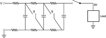
Fig. 20 Many TEA lasers employ Marx bank capacitor systems. A typical Marx bank configuration is shown in Figure 21. The basic idea of a Marx bank is to charge the capacitors in parallel and discharge them in series. In the figure, the charging is done with the switches open, at a voltage V, below the value that will break down the gas and begin the discharge. Then the switches are closed rapidly and the capacitors are in series. The voltage across the tube is now 3V, above the breakdown voltage, and the discharge can begin. The figure shows three stages, but Marx banks can have many more than three stages. Marx banks are suitable for providing the fast-rising pulses (1-2 microseconds) suited for many pulsed gas lasers.
Fig. 21 The excitation of a TEA laser is transverse, that is, perpendicular to the optical axis of the device. This keeps the total voltage requirements reasonable. The optimum electric field in a carbon dioxide laser discharge should be of the order of magnitude of 30 V/cm per torr of gas pressure. This is the optimum value needed to accelerate electrons to the proper velocity to effectively excite the gas. For a continuous laser, operating at low gas pressure, it is possible to supply the field axially, along the length of the tube, without having the total voltage become too high. But for a laser operating at a gas pressure of one atmosphere (760 torr), the voltage for a one-meter-long device would exceed two million volts, an unreasonably high value. Thus, the excitation is transverse, over a much shorter distance, and the total voltage can be kept down to some tens of kilovolts. We already have seen one method by which the discharge in a TEA laser can be controlled by means of a ballast resistor and a pin cathode structure. Modern commercial TEA lasers generally use a double-discharge approach. A low-energy preionizing discharge causes some level of ionization to be present in the gas when the main discharge occurs. This makes it more likely that the discharge will form throughout the volume of the gas. This approach greatly improves the stability and uniformity of the main discharge. A power supply to accomplish this is shown in Figure 22. The supply circuit is a two-stage Marx bank. The cathode is in the form of flat metal bars, parallel to each other. Trigger electrodes are placed between the strips that make up the cathode. The anode is a sheet of aluminum. The trigger electrodes are connected to the anode. When the discharge begins, the gap between the cathode and the trigger electrode experiences the full anode-cathode voltage over a very short distance. The resulting electric field is very high (>105 V/cm). This leads to emission of electrons from the cathode. The electrons form a sheath around the cathode so that when the main discharge occurs between the cathode and anode, the discharge is very uniform and involves the entire gas volume.
Fig. 22 Another method of controlling the discharge is the use of electrodes in the form of bars with a so-called Rogowski profile. This is a somewhat crescent-shaped cross section. Near the edge of the bar, the radius of curvature decreases gradually so that the value of the electric field does not become larger than its value in the plane portion of the bar. With these approaches, the use of short (microsecond) pulses so that arcs do not have time to form, the use of shaped electrodes, and the use of preionization and double discharges, the formation of arcs can be inhibited and TEA lasers can operate reliably. Finally, to show another variation of TEA laser power supplies, we present in Figure 23 a power supply for a large research TEA laser. This was also a double-discharge device. The storage capacitors C formed a two-stage Marx bank and were charged to 55 kV. The cathode was solid aluminum and the anode was stainless steel mesh stretched over an insulating frame. Internal to the anode were many internal trigger electrodes, each with a 100-pF capacitor in series. When the spark gap was triggered, the Marx bank discharged and the voltage between the anode and the trigger electrodes built up and caused a corona discharge that acted as the source of preionization. When the preionization had built up, the other spark gaps fired and the discharge between the main electrodes occurred. This system was capable of producing pulses with pulse energies of 300 J, a very high value for TEA lasers.
Fig. 23 The prime attraction of the TEA laser is its ability to produce short, intense pulses from a device that is modest in size. The TEA laser represents an important class of high-power pulsed infrared laser, with pulse durations in the submicrosecond to microsecond range and with peak powers in the multimegawatt regime. TEA lasers have important applications in industrial materials processing. To summarize, carbon dioxide lasers represent relatively mature technology and are widely available commercially. Models with continuous outputs that range from a few tens of watts up to 45 kilowatts are available, with models incorporating slow axial gas flow, fast axial flow and transverse flow all being offered. Small models of continuous carbon dioxide lasers can operate from 120-volt single-phase sources, but larger devices require 440/480 3jD three-phase input. Typical electrical power requirements are 10-20 times the rated output power. Many models of commercial carbon dioxide TEA lasers are also available, with electrical requirements ranging up to 50 amperes of 208 vac 3 j wye.
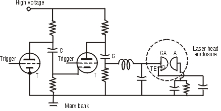
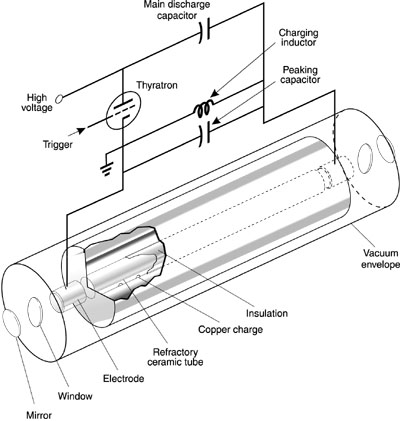
Power Supplies for Metal Vapor Lasers We turn now to a class of pulsed metal vapor lasers. The power supply requirements for these pulsed lasers become more complex than what we have considered previously. Pulsed metal vapor lasers first were developed around 1966 but were slow to mature. The technology of these lasers has been difficult, primarily because of the high temperature at which the laser tube must be operated to keep the metal in vapor form at a reasonable pressure (around 1500° C in the case of gold). Because these lasers offer desirable wavelengths, they have been developed to commercial status and are now reliable, robust commercial products. A metal vapor laser may consist of a ceramic tube with pellets of metal (such as gold or copper) positioned inside. The tube is surrounded by a cooling water jacket. An electrical discharge through a gas (neon) in the tube heats the metal and produces a low-pressure vapor. The laser is essentially a pulsed device, with a high pulse-repetition rate (kilohertz) so that the beam appears continuous to the eye. The beam diameters are typically one inch or more, larger than those of most familiar visible lasers. Commercial pulsed metal vapor lasers are copper (511- and 578-nm wavelengths) and gold (628 nm). Experimental demonstrations have included lead (723 nm), manganese (534 nm), and barium (1500 nm). The availability of these wavelengths from small devices with short pulse duration has allowed development of a number of novel applications, such as photodynamic therapy in medicine and high-speed photography. Although such lasers are still not common, they are beginning to be used for industrial material processing. The short wavelength and high peak power allow high irradiance to be delivered to a small area on a workpiece. Of the metal vapor lasers, copper is the most highly developed. Figure 24 shows a schematic diagram of a pulsed copper vapor laser. Some of the details of the construction necessary to deal with the presence of a metal vapor at very high temperature are indicated. The basic elements of the pulsed power supply include a DC charging power supply that charges a capacitor and a thyratron trigger, similar to elements that have been described above. When the thyratron is triggered, the capacitor, charged to a voltage above the breakdown voltage of the tube, discharges through the tube, creating a pulsed electrical discharge through the tube, leading to laser operation. The use of the peaking capacitor helps to increase the efficiency of deposition of electrical energy in the gas. The relatively simple circuitry indicated here has problems. First the current flow through the thyratron leads to erosion of the electrodes and shortened life for the thyratron. Second, the power supply is coupled to a load whose impedance is changing rapidly during a very brief pulse. Our earlier discussions have centered on lasers for which this was not so serious an issue. It is not a serious problem with continuous lasers, and carbon dioxide TEA lasers do not show so great a change in gas impedance. Thus, we have not had to deal with this issue. But the rapid change in impedance of the tube makes it difficult to control the current pulse and to optimize it. This leads to reduced efficiency for the laser.
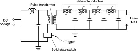
Fig. 24 Figure 25 shows a diagram of an advanced power supply for metal vapor lasers based on use of saturable inductors. The symbol for a saturable inductor is indicated in the figure. The saturable inductor is a toroidal core of ferrous metal (cobalt-based alloy) with insulated wire wound through it. The use of a saturable inductor helps to control the rate of the current risetime. The circuit employs a network of saturable inductors and capacitors. This network serves as a magnetic pulse-compression circuit and shortens the pulse duration from 5 microseconds to about 130 nanoseconds. The pulse duration is thus much better matched to the requirements of the laser discharge. Designs such as this have provided improved control of the current flow through the laser tube and increased efficiency of the use of the stored electrical energy. Because less energy must be stored in the storage capacitor, the lifetime of the switches also is extended. The figure also indicates the use of a solid-state switching device, which has longer lifetime than thyratron tubes.
Fig. 25 Figure 25 also shows the use of a pulse transformer to increase the voltage in the discharge portion of the circuit. This is a common feature in the power supplies of pulsed gas lasers, allowing the storage portion of the circuit to operate at lower voltage. Figure 25 is presented as one out of many possible examples for advanced power-supply designs for metal vapor lasers. Commercial copper vapor lasers emit average powers ranging from a few watts to more than 100 watts. The two wavelengths 511 and 578 nm are emitted simultaneously, with about 2/3 of the power at the shorter wavelength. The output is in the form of short pulses with duration in the 10-20-ns range at pulse repetition rates up to 20 kHz. The input power required ranges from a few kW for small devices to around 16 kW for larger ones. Typical small units operate on 220-V AC single-phase input and larger models use 220-V or 415-V three-phase input. Commercial pulsed gold vapor lasers can emit up to several watts of average output power. The other characteristics are similar to those of the copper vapor lasers.
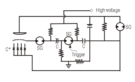
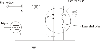
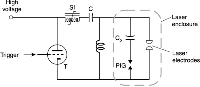
Excimer Laser Power Supplies Excimer lasers are notable for their capability to produce high-power radiation in the ultraviolet portion of the spectrum. Excimer lasers are in principle scalable to large high-efficiency devices. Operation in the ultraviolet means that the diffraction-limited spot can be very small, smaller than for other high-power lasers. In addition, the short wavelength generally means that there will be good coupling of the energy to a workpiece. The term excimer is derived from the word dimer, meaning a diatomic molecule formed by the union of two atoms. If the molecule is in an excited state, it is referred to as an excited dimer, or excimer. The excimer lasers use molecules that contain the noble gases, which do not form chemical compounds under normal circumstances. However, the noble gases may form compounds that have no stable ground state, but that may have excited states that are temporarily bound. An example is krypton fluoride. A gas mixture that contains krypton and fluorine is excited in a pulsed electrical discharge. In a chain of complex processes, the metastable excited state KrF* is produced. The asterisk denotes that the molecule is in an excited state. The excited state is bound for a short time and then dissociates according to the reaction KrF* ® Kr + F + hv where hv represents a photon with energy corresponding to a wavelength of 249 nm. Because there is no stable ground state, the population inversion needed for laser operation is obtained easily. Excimer lasers are necessarily pulsed devices, with pulse duration in the nanosecond regime. The emission of the photon causes the KrF* molecule to fall to its lowest energy state in which the two atoms repel one another, so that the molecule breaks up. Thus, even though the noble gases like krypton do not form stable chemical compounds, it is possible for them to combine briefly in excited states to form transient short-lived molecules, which can emit laser light as they break up. In addition to the 249-nm wavelength of KrF, other common excimer lasers include ArF (argon fluoride, 191 nm), XeCl (xenon chloride, 308 nm), and XeF (xenon fluoride, 351 nm). Excimer lasers have used two main methods of excitation: pulsed electric discharges or high-energy electron beams. Development of excimer lasers has branched into two channels that represent the two excitation methods. Electron-beam-excited devices are capable of producing very high energy pulses. Electron-beam excitation involves large, expensive sources of high-energy electrons. Such devices can be scaled to very large size and are capable of reasonably high efficiency, potentially in the 5- to 10-percent range. Devices have been constructed with energy in the kilojoule range, and amplifiers with energy-extraction capability in the hundred-kilojoule range appear possible. Such devices are large and expensive and consume many resources. They have been used in areas such as laser-assisted thermonuclear fusion and military research. Electric-discharge excimer lasers may be much smaller and less expensive. They are the devices that have found applications in industry for semiconductor fabrication, remote sensing, photochemistry, and material processing. Their energy-extraction capabilities are much lower than those of the electron-beam devices. Typical characteristics for commercial models are pulse energy of from a few tenths of a joule to a few joules per pulse and pulse repetition rates of tens to hundreds of hertz, with average power in the range of one hundred watts. Within the scope of this module, we shall discuss the power supplies for only the electric-discharge devices. Because of the unstable nature of the chemical species in an excimer laser, it is available only as a pulsed device with short pulses, typically in the 200-nanosecond regime. The problems with the changing impedance of the gas during the discharge become more severe. The change is much faster and covers a greater range than is the case for carbon dioxide laser gas mixtures. Excimer lasers require short excitation pulses with rise times in the range of tens of nanoseconds and currents in the range of kiloamperes. Also some means for preionizing the gas between the electrodes is required. The usual approach has been a two-stage circuit in which charge is stored on a storage capacitor, and then transferred by a thyratron switch to an array of secondary capacitors, called peaking capacitors. The basic idea is to be able to store the charge in one portion of the circuit, where the process can be relatively slow, and then to perform the discharge in another portion of the circuit, which can be much faster. The charge is transferred across preionization spark gaps that introduce some charge into the gap between the electrodes and prepare the gas for the main discharge. Figure 26 shows an early type of discharge circuit that employs this exchange of charge between the main storage capacitor C and the peaking (or pulse) capacitors Cp.
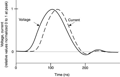
Fig. 26 A circuit such as this will be adequate for operation of excimer lasers operating at relatively low pulse-repetition rate and with moderate pulse energy. However, the design is stressing for the thyratron and the lifetime of the thyratron in a circuit like this tends to be short. Some of the problems of driving an excimer laser discharge may be understood with reference to Figure 27, which shows voltage and current waveforms for an excimer laser discharge. After switching, the voltage rises rapidly, reaching the breakdown voltage of the gas mixture within less than 100 nanoseconds. Then the current begins to flow. But because of the negative resistance characteristics of the discharge, the voltage drops rapidly as the current rises. This makes it difficult to accelerate the electrons in the discharge to the velocities needed to excite the laser species. Also, the power (voltage-current product) dissipated in the discharge is not as large as would be desired, because the voltage is dropping so rapidly as the current increases. This reduces the efficiency of the device This in turn means that, for a given laser output, more energy must be stored and switched by the circuit, making the power supply more expensive and reducing the life of the thyratron. Also, the figure shows the possibility of current reversal, which is another undesirable feature. Reversal of the current can damage the thyratron.
Fig. 27 Power-supply designs for excimer lasers have been developed to minimize these effects and to increase the efficiency of the use of the stored energy. There appear to be two main approaches employed in commercial electrical-discharge excimer lasers. One is shown in Figure 28. In this design, a saturable inductor is used as a magnetic switch control. It decouples the relatively slow charging portion of the circuit, including the thyratron, from the very fast discharge portion of the circuit. It thus reduces the peak current carried by the thyratron and extends the life of the thyratron. In addition it eliminates the possibility of current reversal. With the magnetic-switch control function, the discharge portion of the circuit can be designed for optimum matching of the low impedance of the laser gas mix, leading to a rapid discharge and increased laser efficiency.
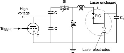
Fig. 28 A second approach to commercial laser power-supply design is shown in Figure 29. This design also employs a saturable inductor. It uses peaking capacitors that are internal to the laser housing, within the laser gas and close to the main electrodes. The internal capacitors allow design of a discharge circuit with low inductance and hence with faster discharge. In addition, placing the peaking capacitors internal to the laser reduces the number of feedthroughs into the laser housing.
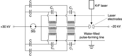
Fig. 29 The advances in power-supply design have improved excimer laser performance substantially, increasing the efficiency and significantly increasing the lifetime of the thyratron switches. The efficiency of commercial KrF lasers can be as high as 4.5%. As a final example, we consider an advanced experimental power-supply design, shown in Figure 30. This XeCl laser used a pulser circuit that provided a fast voltage pulse to the primary windings of two transformers surrounding one of the electrodes. A voltage of opposite polarity was induced in the secondary windings that fed the second electrode. The combined voltages exceeded the breakdown threshold of the gas mix and led to a rapid discharge. This circuit employed a deionized-water pulse-forming line and preionization by irradiation with ultraviolet light from a KrF laser. The gas mix contained a small amount of flourobenzene vapor, which was easily ionized by the KrF laser light. This example is intended to illustrate innovative approaches to advance the efficiency of extraction of energy from excimer lasers.
Fig. 30 Excimer lasers have reached commercial status while continuing improvements are increasing their reliability and lifetimes. Small excimer lasers may draw currents around 10 amperes and use single-phase 120-V AC wall plug sources. Larger devices draw currents of tens of amperes to one hundred amperes, and require 220-V or higher three-phase input power.
|