| This version reflects the comments of the core participants as reviewed and incorporated in accordance with CORD's FIPSE-supported Curriculum Morphing Project. | |||||||||||||||||||||||||||||||||||||||||||||||||||||||||||||||||||||||||||||||||||||||||||||||||||||||||||||||||||||||||||||||||||||
MODULE 3-14
The collimated nature of laser light creates an intense beam which appears to emanate from a point source at some distance behind the laser output aperture. This allows the beam to be focused by the human eye to microscopic, retinal spot diameters. These circumstances lead to high irradiance and create potential ocular hazards from both direct and reflected beams. In order to recognize potential laser hazards, it is necessary to be able to mathematically express the various conditions which may occur in the normal use of the beam. This module investigates the various conditions of both direct and reflected laser light in order that the basic calculations for hazard analysis can be accomplished. In the laboratory, the student will evaluate the optical hazards presented by laser beams under several laboratory conditions. 
Upon completion of this module, the student should be able to: 1. Calculate the optical gain of the human eye given the diameter of a focused beam, the average diameter of the eye pupil, and assuming that the cornea transmits to the retina all of the power incident upon it. 2. Calculate the irradiance at the retina produced by a laser beam of known divergence and output power, given the focal length of the eye lens and assuming no reflection or transmission losses. 3. Calculate the irradiance that is incident upon a diffuse reflector target from a laser of known beam divergence, power, and beam size at a known range from the laser. 4. Calculate the reflected radiance from a diffuse reflector with a known irradiance incident upon the surface. 5. Calculate the irradiance of a diffusely reflected laser beam of known power at a given range and angle from the surface. 6. Calculate the irradiance incident upon a diffuse surface that produces a known retinal irradiance in the eye of a Rhesus monkey of known pupil size and ocular transmission. 7. Using equipment and procedures given in the text:
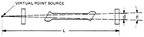
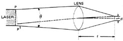
Beam Divergence and Virtual Point Sources The eye hazards presented by laser beams depend upon the low divergence of the beam and the eye’s ability to focus such a low-divergence beam to a small spot on the retina. The emission from most lasers can be considered as emanating from a "virtual point source" located within or behind the laser device. A "virtual point source" is one which really does not exist, but the properties of the emitted beam are such that there appears to be a source at this position. The geometry necessary to locate the virtual point source is shown in Figure 1. The distance of the virtual point source behind the front mirror of the laser can be related to the diameter d of the beam at the mirror and the laser beam divergence by Equation 1.
Fig. 1 For small beam divergences, the tangent of an angle is approximately equal to the angle expressed in radians. Thus tan where q is expressed in radians. Thus, Equation 1 becomes Equation 2 by substitution.
Example A illustrates the use of this equation to calculate the location of the virtual point source for a HeNe laser.
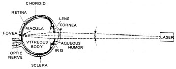
Focusing of Laser Beams by the Eye Consider now the ability to focus a beam from a laser. Since the laser can be considered to be a point source as verified in the previous discussion, the light can be focused to a spot size that, in theory, approaches the dimensions of the beam wavelength. In practice, however, the focused spot size will be larger than this so-called diffraction-limited spot size, in which the beam spread from the laser results only from diffraction effects. Most lasers have a beam spread that is larger than the theoretical limit. A simple geometrical argument can be used to calculate the spot size that occurs on the retina, at the back of the eye when a beam is focused by the eye lens. The condition of a visible laser beam directly incident on the human eye is depicted in Figure 2. This is considered to be the intrabeam viewing condition because all of the direct laser beam enters through the pupil and is focused upon the retina. Such a condition can occur from a direct exposure to the beam or to a specular reflection such as from a mirror-like surface.
Fig. 2 From the geometry shown in Figure 3, the diameter d of the laser beam focused on the retina can be calculated using the following equation: tan But since tan
Thus, the spot diameter may be given by Equation 3:
Fig. 3
The spot size of a beam focused on the human retina can now be easily calculated. Example B illustrates this using the beam from the previous example where q = 0.5 mrad and assuming that the focal length f of the human eye is 1.7 cm. To give some idea of how small this focused spot is, consider that 8.5 micrometers is approximately the size of one human blood cell.
The irradiance of the retina can be calculated by determining the area of the focused spot and dividing the beam power by this area. This is illustrated in Example C.
Example D is a calculation of the irradiance on the cornea of the eye assuming that the same laser beam just fills a 7-mm pupil.
Comparison of Examples C and D reveals that under the "worst case" conditions a corneal irradiance of only 5.26 mW/cm2 can result in a retinal irradiance of 3.52 × 10³ W/cm2. This assumes the "worst case" where the pupil is fully dilated to a 7-mm diameter, thus allowing an area of the beam equal to 0.38 cm2. The optical gain (OG) of the eye is defined as the ratio of the transmitted retinal irradiance, TER, to the corneal irradiance, EC. From the Examples C and D: Optical gain = where we have assumed 100% transmission (T = 1.00) in the eye. The student can verify that the optical gain can be related by the simplified Equation 4:
The importance of these mathematical arguments is to demonstrate that the irradiance at the retina is increased nearly one million times above the irradiance incident upon the cornea when directly viewing a HeNe laser. As a result, the theoretical irradiance at the retinal surface when directly viewing a 1-mw HeNe laser is well over one kilowatt per square centimeter. Such a value is extremely close to the irradiance necessary to cause a permanent retinal lesion with a very short exposure time.
Retinal Images of Diffuse Reflections Consider the case of directly viewing a diffuse reflection. In practice, most non-glossy surfaces which are slightly rough act as a diffusing surface to an incident laser beam, which emits visible or near-infrared radiation. Figure 4 illustrates the geometry of a diffuse reflection of a laser beam. In effect such a rough surface acts as a plane of infinitesimal scattering sites which reflect the beam in a radially symmetric manner. Consequently, the reflected radiant intensity (power per unit solid angle), denoted by the symbol I (f ), is dependent upon the cosine of the angle f measured from the normal to the surface and is given by Equation 5.
Fig. 4 This relationship is known as a Lambert’s Law, and a surface which behaves in this manner is often referred to as an Lambertian surface. This surface defines an ideal plane diffuse reflector. Figure 5 shows the distribution of light energy reflected from such a surface.
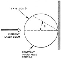
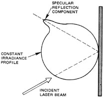
Fig. 5 It should be stressed that "rough" surfaces do not act as diffuse reflectors at all wavelengths. For example, brushed aluminum (which may partially diffuse for visible-frequency laser radiation) is a good specular reflector for far-infrared radiation as emitted from a carbon dioxide laser. Hence, caution must be exercised when assuming that diffuse reflections result from "rough" surfaces for all laser types. Additionally, most slightly "rough" surfaces may still have some properties that allow a small component of specular reflection. This may occur with just a few percent of the incident radiation specularly reflected and the remainder diffusely reflected. This behavior is generally the rule—and not the exception—for most common surfaces. As a result, the reflected radiation is not exactly radially symmetric, but has a skew in a constant irradiance profile that corresponds to the direction of the specularly reflected component, as shown in Figure 6.
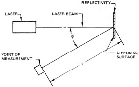
Fig. 6 It can be shown that the radiance L (often called the "brightness") of a plane diffuse Lambertian surface is related to the irradiance incident on the surface by Equation 6. This equation allows the calculation of radiance of a diffusely reflected laser beam while knowing only the irradiance incident upon the surface and the reflectivity of the surface. In a case such as that shown in Figure 7 all that is necessary is to determine the irradiance on the diffusely reflecting wall and the reflectivity of the wall material.
Fig. 7 As seen in Figure 7, the irradiance at range R can be calculated if the laser power (P) and the beam areas (As) are known at that point. Thus:
But, from the geometry, one can see that: DL = a + 2X
Hence, at very close ranges, the laser spot size is simply Consideration of the geometry will show that: tan Hence, as before in the module, for small divergence angles, tan Thus, we can write: 2X = R q , and the relationship for the irradiance becomes:
The above equation is usually referred to as the laser range equation and is useful in calculating potential hazard levels "down range" from the laser. Example E shows the use of Equation 7 to calculate the irradiance of a HeNe laser at a range of 10 meters and the resulting radiance of the reflected beam.
For comparative purposes, consider that when a person stares directly at a standard 100-watt frosted light bulb, he views a diffuse light source with a radiance of about 40 × 10–3 W/cm2 · sr. Hence, viewing the diffuse reflection of a 1.0 × 10⁻³ watt laser directed onto a wall 10 meters away is actually 48 times less "bright" than directly viewing a 100-watt light bulb (which should tell you something about long-term staring at 100-watt light bulbs)! However, comparison of the irradiance on the wall produced by the 100-watt light bulb 10 meters away can be shown to be nearly 8.0 × 10⁻⁶ W/cm2. The calculation for the 1.0 × 10⁻³ watt laser indicated an irradiance of 2630 × 10–6 W/cm2—or nearly 330 times greater! The reflected irradiance from a Lambertian surface at some distant point is inversely related to the square of the distance from the surface (see Figure 8). This is expressed in Equation 8.
Fig. 8 As a result of this inverse-square relationship, the reflected irradiance from a diffuse surface decreases as the square of the distance from the surface. That is, if one doubles the distance from the diffuse reflector, the irradiance falls by a factor of four. If one moves 10 times the distance, the irradiance falls by 100 times! Consequently a diffuse surface acts as a distance-dependent "filter" which permits indirect viewing of some low-powered laser beams. Obviously, if the laser power is sufficient, even a diffuse reflection is hazardous to view. This is an important factor for those working with high-powered lasers, namely, that even a diffuse reflection can be hazardous and other control methods are required for safe use. Contrary to common belief, where a diffuse surface acts as an extended source, the retinal irradiance produced actually is not dependent on the distance but remains constant. This is related by the equation: (note that the range is not a parameter in the following equation for retinal irradiance).
Assume, for the sake of example, that the "safe" irradiance at the retina for long-term exposure is 0.29 mW/cm2. (Long-term exposure is considered greater than 10,000 sec.) The irradiance incident upon the diffuse surface which would be acceptable for long-term (all day) viewing of a diffuse reflector surface may be calculated by solving Equation 9 for the irradiance incident upon the diffusing surface (r = 1.0): ES = ES = = 6.8 mW/cm2 There are some instances where it is useful to calculate the distance from a diffuse reflector at which a specific irradiance occurs. For example, assume that a 1-mW HeNe laser is directed upon a surface which has a 90% reflectance (it will absorb 10% of the incident laser energy). Also, assume normal viewing (q = 0 degrees, thus cos q = 1.0). At what distance does an irradiance of 1.0 × 10⁻⁶ W/cm2 occur? Using Equation 8 and solving for the distance r yields: r = r = 16.9 cm In a similar manner, one can verify that the distance required for a 1.0 × 10⁻⁶ W/cm2 irradiance from a 1.0-watt laser (from the same diffuse reflector) will be nearly 535 cm.
Summary This module has presented the equations and calculations necessary in determining the eye hazard and corneal and retinal hazards associated with laser radiation. Quantities that must often be determined are irradiance on surfaces down range from the laser, corneal irradiance, retinal irradiance, and the safe viewing conditions and distances from various diffuse reflections. This leads to consideration of specific control measures for situations where the intensity of the laser beam is at or above levels which are not considered safe. Many recent safety standards have been proposed for this purpose, the most important of which is the ANSI Z-136.1 standard for the Safe Use of Lasers published by the American National Standards Institute (ANSI).
1. Calculate the optical gain of the human eye when the laser spot focused on the retina has a 100-micrometer diameter. Assume a 7-mm pupil diameter. Calculate the retinal irradiance which would occur for this focused spot for a 5-mW HeNe laser in the condition of intrabeam viewing. (Assume 100% transmission.) 2. Using the laser range equation, calculate the irradiance of an argon laser of 1.0-watt power which is incident upon a diffuse reflector at a distance of 100 meters from the laser. Assume a laser beam divergence of 1.0 × 10⁻³ radians and an emergent beam size (at the laser) of 2.0 mm. 3. In problem 2 above, calculate the radiance of the reflected beam. Assume a reflectivity of 80%. 4. What is the irradiance of a diffusely reflected 100-W YAG laser at a distance of 25 meters from the diffusing surface (r = 0.70) and when viewed at an angle of 45° . 5. If the long-term "safe" irradiance for retinal tissues in the Rhesus monkey is 0.30 mW/cm2, what is the irradiance incident upon a diffuse surface (r = 0.5) which produces this irradiance in a Rhesus monkey eye (focal length = 1.0 cm). Assume 100% transmission and that the pupil diameter is 5 mm.
HeNe laser (1-2 milliwatt) Optical power meter Centimeter rule (10 cm) White cardboard target (2" × 2") First surface mirror Positive lens, +40 mm focal length, and lens holder Cardboard beam stop (12" × 12" flat black), on base Large piece of paper, preferably a dark color (approximately 1 meter square) Protractor Two alignment targets (one with a hole punched at beam height)
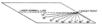
1. Place a large piece of paper on the lab table. Draw a line (the "normal" line) which bisects the paper. At one edge mark "laser," and at the opposite edge mark a dot for the target position, as shown in Figure 9.
Fig. 9 Now, using a protractor, accurately mark the angles from the target dot of 10° , 20° , 30° , 40° , 50° , 60° , 70° , 80° , and 90° with respect to the normal line as shown in Figure 9. 2. With the laser turned off, arrange it on the table so that the beam would be directed towards the "target" point along the normal line. Place a cardboard target at this point which has a line drawn perpendicular to the normal line as shown in Figure 10. It may be convenient to place a second such target, with a small hole punched in it to allow the beam to pass, at a position just in front of the laser. Now, turn on the laser and make adjustments in its position so that the beam travels toward the target exactly on a line above the normal line. The laser should not be moved from this position during the remainder of the procedure. Now turn off the laser.
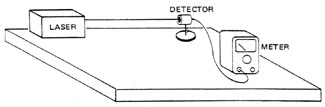
Fig. 10 3. Arrange the detector head of the power meter in the path of the beam along the normal line, as shown in Figure 11. Adjust the meter setting to a range setting of at least 10 × 10–3 W. Turn on the laser and adjust the range setting to give the best reading and measure the total laser power. Turn the laser off.
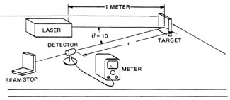
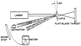
Fig. 11 4. Place the first surface mirror in the target position. Arrange the HeNe laser, beam stop, and power meter detector approximately as shown in Figure 12. Turn on the laser. Make fine adjustments in the mirror position until the beam is directed onto the detector surface at an angle q = 10° . At a distance r = 10 cm, measure the total power. Repeat the measurement at angles of q = 40° and 70° . Record this data in Data Table 1.
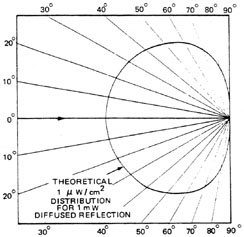
Fig. 12 5. Repeat step 4 at a distance of r = 20 cm and 40 cm for an angle of incidence 6. Place the white cardboard in the target position. Adjust the target such that it is normal to the laser beam. Position the detector at q = 10° at a distance of r = 10 cm and measure the reflected irradiance (W/cm2). Repeat for q = 40° and q = 70° . Record this data in Data Table 2. 7. Repeat step 6 for distances r = 20 cm and r = 40 cm for all three angles (q = 10° , 40° , 70° ). Record this in Data Table 2. 8. At an angle q = 10° , by moving the detector head in and out along the line, locate the distance (r) at which the irradiance is 1.0 × 10⁻⁶ W/cm2. Record this in Data Table 4. 9. Repeat step 8 for angles q = 20° , 30° , 40° , 50° , 60° , 70° , 80° , 90° . Record these values in Data Table 3. 10. Plot a constant 1 × 10⁻⁶ W/cm2 irradiance profile such as the graph shown in Figure 13 using the data from Data Table 3. How does this agree with the theoretical values?
Fig. 13 11. Place a positive lens (focal length: + 40 mm) in the path of the beam at an angle q = 10° in an arrangement as shown in Figure 14. Locate the reflections from the two lens surfaces and measure each beam separately making certain that the entire beam enters the detector head. Record this in Data Table 4.
Fig. 14 12. Note that the reflected beams expand in relation to the curvature of the lens surface. Move about one meter distance away from the lens to a point where the beam is about 5 cm diameter. Then by moving the detector head, locate the point at which the irradiance of the reflected beam is equal to 1 × 10⁻⁶ W/cm2. Measure this distance and record it in Data Table 4.
Data Table 1. Specular Reflections.
Data Table 2. Diffuse Reflections.
Data Table 3. Diffuse Reflection – 1 W/cm2 (Lambert’s Law).
Data Table 4. Reflection from a Lens.
American National Standard for the Safe Use of Lasers. ANSI Z136, 1-1976. American National Standards Institute. Control of Hazards to Health from Laser Radiation. U.S. Department of the Army Technical Bulletin TB-MED-279. (September 18, 1974). Goldman, Leon and Rockwell, R. James, Jr. Lasers in Medicine. Gordon and Breach, 1971. Ham, William T., Jr. The Eye Problem in Laser Safety. Arch. Environ Health 20, 156, 1970. Laser and Microwave Hazards Course Manual. Arsenal, MD: U.S. Environmental Hygiene Agency. Laser Safety Guide. Fourth ed. The Laser Institute of America. A Manual of Safety Precautions for Laser Systems. Chicago, IL: The Illinois State Medical Society. Performance Standard for Laser Projects. Bureau of Radiological Health, Dept. of Health, Education and Welfare. FR-40 (148): 32252-32265 (July 31, 1975). RCA Electro-Optics Handbook. Technical Series EOH-10. Harrison, NJ: RCA Commercial Engineering. Sliney, David and Wolbarscht, Myron. Safety with Lasers and Other Optical Sources. New York: Plenum Press, 1980. Winburn, D.C. The Safety Program for Laser-Fusion Research at Los Alamos Scientific Laboratory. Report LA-UR-73-933. |
|||||||||||||||||||||||||||||||||||||||||||||||||||||||||||||||||||||||||||||||||||||||||||||||||||||||||||||||||||||||||||||||||||||


 for small angles, this
equation may be written as
for small angles, this
equation may be written as

 = 6.69 ´ 105


 . For long ranges (usually anything greater than a few meters), one
must include the divergence factor 2X.
. For long ranges (usually anything greater than a few meters), one
must include the divergence factor 2X.


 (W/cm2)