| This version reflects the comments of the core participants as reviewed and incorporated in accordance with CORD's FIPSE-supported Curriculum Morphing Project. | ||||||||||||||||||||||||||||||||||||||||||||||||||||||||||||||||||
MODULE 3-9 Lasing has been observed in a large number of molecular gases. Of particular importance is the carbon dioxide (CO2) molecular gas laser, which has lasing transitions at several wavelengths in the infrared, principally around 9.6 m m and 10.6 m m. Development of the CO2 laser has proceeded at a fast pace. CO2 lasers are capable of continuous, repetitively-pulsed, Q-switched, and mode-locked operation with high energy outputs and large working efficiencies (10%-30%). Furthermore, they emit light at a frequency exhibiting little atmospheric absorption. An important area of industrial application for CO2 lasers has been in materials processing, including hole drilling in various substances, paper cutting and perforation, cloth cutting, scribing of semiconductor wafers, and welding. In addition, carbon dioxide lasers are being used in laser-induced fusion studies, experimental optical communications and tracking systems, and in environmental testing and monitoring. The purpose of this module is to examine some of the optical and electrical properties of both CW and pulsed CO2 gas lasers. Excitation mechanisms and the effects of gas flow rates on laser output will be discussed. A flowing, longitudinally-excited CO2 laser will be operated in the laboratory in both CW and repetitively-pulsed modes, and its output parameters will be measured.
Upon completion of this module, the student should be able to: 1. Explain the primary factor that limits output power of Class I CW CO2 lasers. 2. Draw and label a diagram showing a CO2 laser with two plasma tubes and a folded optical system. Include a simple diagram of the electrical system usually used in such lasers. 3. Compare characteristics of the following materials when they are used as CO2 laser mirror substrates. Explain the practical application of each material in CO2 laser optical systems.
4. Explain the fundamental difference between a Class I CO2 laser and a Class II CO2 laser. Include comparisons of the following quantities:
5. Draw and label a diagram showing the typical configuration of a Class III CO2 laser including the excitation mechanism, heat exchanger, blower, optical cavity, and direction of gas flow. 6. Draw and label a diagram showing the essential elements of an electron-beam ionized, CW CO2 laser. The diagram should include emitter, sustainer electrodes, membrane, high-vacuum region, working medium, electron beam, optical axis, and gas flow direction. 7. Explain how excitation of CO2 molecules to the upper lasing level is achieved in an E-beam ionized CO2 laser. 8. Draw and label a diagram showing an anode-pad excited CO2 laser. The diagram should include anode pad, cathode, gas flow direction, mirrors, and optical axis. 9. Draw and label a diagram showing elements of a gas dynamic laser. The diagram should include burner, mixing chamber, quick-freeze or gas expansion nozzles, optical cavity, diffuser nozzles, and gas input ports. 10. Given parameters of the optical cavity of a Class I CO2 laser operating in an optimized condition, calculate approximate output power of the laser. 11. Explain why average and peak powers available from a TEA CO2 laser increase with the square of the gas pressure. 12. Draw and label diagrams showing electrode configurations for each of the following TEA CO2 lasers:
13. Use procedures and equipment given in the module to align the optical cavity of an axially-excited CO2 laser.
Continuous Wave CO2 Lasers In Module 3-8, "Energy Transfer in Molecular Lasers," principles of operation of molecular lasers were presented, with the carbon dioxide (CO2) laser studied as an important example. This module describes the more important types of CO2 lasers that have scientific, industrial, and military applications. A wide variety of configurations have been employed for CW CO2 lasers. These range from small versions used in communications with outputs of one watt or less to the giants of the laser industry producing tens of kilowatts. This section discussed design features and output characteristics of important CO2 laser types.
Class I CW CO2 Lasers The Class I CW CO2 laser was the first CO2 laser developed, and continues to be the most common. Figure 1 is a diagram of such a laser. Common characteristics of this CO2 laser class include the following:
Fig. 1 The primary factor that limits output power of these lasers is their inability to efficiently remove waste heat from the gas. (See Module 3-8 for operating curves of Class I CO2 lasers.) Cooling is principally achieved by helium (He) collisions with tube walls. Air cooling of CO2 laser tubes is possible, but this results in an elevated wall temperature and greatly reduces laser efficiency. Smaller CO2 lasers and those used in research often employ water cooling. Industrial CO2 lasers usually use recirculating oil and oil-to-water heat exchangers for better system stability and reduced maintenance. An increase of tube current beyond the recommended operating value results in more heat than can be effectively removed from the system in this manner. Increases in tube diameter also decrease cooling efficiency by increasing the path length necessary for He atoms to reach the walls from the center of the tube. Thus, the only effective method of increasing output power of this type of CO2 laser is to extend the active length. For best results, this must also be accompanied by an increase in gas flow rate. In most larger systems the gas is recirculated with a few percent being replaced on each cycle. Table 1 lists some operating parameters of several Class I CO2 lasers. Table 1. Operating Parameters of Commercial Class I CO2 Lasers.
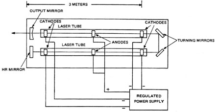
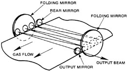
Figure 2 shows the usual method of achieving an extended active length while minimizing overall dimensions and power supply cost. The optical cavity has been folded to utilize two plasma tubes positioned side by side. Commercial CO2 lasers that use six tubes (and ten turning mirrors) are available and achieve powers of 1 kW. The laser tubes shown in Figure 2 have a central anode with a cathode at each end. Separate current regulation is required for each cathode. This is usually less expensive than using a single regulated supply at higher voltages. Typical voltages of 10-15 kV are required for a 1-m discharge, with starting voltage pulses of about twice that value.
Fig. 2 CO2 lasers may be constructed with the mirrors as an integral part of the plasma tube, as shown in Figure 1, or Brewster-angle windows and external mirrors may be used. If mirrors are internal, they and their mounts often will have high electrical potentials. Granite slabs sometimes are used as optical mounting bases in order to isolate these voltages and provide good mechanical stability. Invar alloy provides excellent dimensional stability in systems in which high voltages are not exposed. Four optical materials are commonly used for CO2 lasers. These are listed in Table 2. Germanium (Ge) is the most common output coupler material for lower-power models (< 100 W) because of the cost advantage. It cannot be used on higher-power lasers as it absorbs a significant amount of the laser beam and experiences thermal runaway at approximately 50 ° C. This means that, as the temperature of the substrate increases, its absorption coefficient increases. This leads to higher temperatures and greater absorption until the mirror is destroyed by fracture.Table 2. Characteristics of CO2 Laser Materials.
Gallium arsenide (GaAs) and zinc selenide (ZnSe) are used as output couplers for higher-power CO2 lasers. Gallium arsenide has a lower absorption coefficient than germanium and a higher thermal runaway point. It is also resistant to damage from high peak powers and thus is popular for pulsed CO2 lasers. Zinc selenide has an even lower absorption coefficient, but its thermal conductivity is also low. Zinc selenide has the advantage of transmitting visible light. This makes optical alignment of the laser much easier. Both of these materials are widely used, with zinc selenide being more popular in the high-power kilowatt range for CW CO2 lasers. Because the index of refraction of these materials is high, antireflection coatings are required for all transmitting optical components. Silicon (Si) does not transmit 10.6 m but does have excellent thermal properties and a considerable cost advantage, and it can be more easily fabricated with a spherical surface than can the other materials. This makes it the most widely used material for low-power, CO2 high-reflectance (HR) mirrors, although it is being rapidly replaced by metal mirrors (Cu, etc.) frequently manufactured by single point diamond micromachinery processes. Three common mirror configurations for CO2 lasers are given in Table 3. The long-radius spherical mirror configuration efficiently uses the active medium and provides for ease of alignment. The plane-parallel mirror configuration provides maximum use of the active medium but introduces alignment difficulties. It is used only in CO2 lasers of output powers around a kilowatt. The plane-spherical configuration is a compromise used on most systems. Notice that mirror reflectivity decreases on higher-power systems. Another common characteristic of higher-power models (> 150 W) is the frequent use of water cooling for mirrors, particularly metal elements. Table 3. Mirror Configurations for CO2 Lasers.
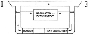
Class II CW CO2 Lasers Figure 3 is a diagram of a Class II CW CO2 laser. The essential difference between this laser and a Class I device is the gas flow rate. The gas is circulated through the system by a high-speed blower. Gas velocity in the laser tube ranges from 100 to 500 m/sec. The primary cooling mechanism is convection rather than conduction to the walls. The heated gas passes through a water-cooled heat exchanger that removes waste heat. Common characteristics of this type of CO2 laser are: · Tube diameters of 8-15 cm. · Tube currents of 700 mA.
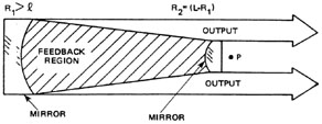
Fig. 3 In this type of laser, a single CO2 molecule is actually in the active region of the tube for less than 0.01 second. The CO2 molecules are removed from the lasing region, cooled, and introduced into the lasing volume again in the ground state. High efficiencies of the heat exchanger and gas flow system make water cooling of the plasma tube less critical, although some systems do have this feature. This efficient removal of waste heat also means that higher tube currents may be used to obtain higher output powers. Because tube walls are no longer involved in the thermal transfer, larger diameters may be used without degrading laser output. Several commercial Class II systems are available in the 1-8 kW power range. Most are folded systems, and all have water-cooled mirror mounts and rigid resonator frames. Most use the same types of optical cavities as the Class I lasers, but some employ the unstable resonator cavity configuration. Figure 4 is a diagram of such an unstable resonator. It consists of a concave mirror and a convex mirror arranged to have a common center of curvature (point P). Both mirrors have reflectivities greater than 99 percent. Light reflects back and forth within the optical cavity, with part of the light passing around the convex mirror to form the output beam. This produces an output beam in the form of an annular ring (doughnut). The cavity configuration in Figure 4 usually is used only on very high-power systems in which partially transmitting mirrors cannot withstand the output power flux. The mirrors used are constructed of metal (usually copper or molybdenum) and are water cooled.
Fig. 4
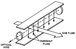
Class III CW CO2 Lasers In this type of laser, often called a "gas transport laser," the cooling principle of the Class II device has been carried a step further. Figure 5 is a basic diagram of a Class III CW CO2 laser. In this laser, the gas flow, current flow, and optical axis are all perpendicular to one another. Typical gas velocities are the same as those of Class II lasers, but the length of the gas flow path that is within the lasing region is reduced to a fraction of a meter. A typical gas molecule spends only about 2 msec in the active region. This is about the duration of the lifetime of the upper laser level. Thus, a CO2 molecule lases from the (001) state to the (100) state and is immediately removed from the system. It is then cooled by a heat exchanger and sent through the system again.
Fig. 5 Figure 6 shows a typical configuration for a gas transport laser. High-speed gas passes through the excitation region, where the nitrogen molecules are raised to a high vibrational state by electron collisions. Collisions between the N2 molecules and ground-state CO2 molecules then excite the CO2 molecules to the upper lasing level. By this time, the gas has moved downstream and into the optical cavity. Lasing occurs, and the gas continues on to the heat exchanger. The gas mixture in all CO2 lasers discussed thus far is essentially the same. In this system (and in the Class II lasers) the He atoms help to transfer waste heat from the CO2 molecules to the heat exchanger. A small amount of gas (approximately 0.005%) is removed and replaced during each cycle through the laser to help maintain impurities at a low level.
Fig. 6 The optical cavity of the Class III laser is usually folded as shown in Figure 7 in order to achieve maximum use of the excited gas. All mirrors except the output coupler are water-cooled silicon or copper. In some models, the output mirror is zinc selenide. For the most powerful systems, unstable resonators are most frequently used.
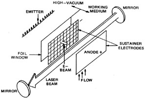
Fig. 7 Above powers of about 10 kW/cm2, there are no suitable window materials for CW CO2 laser systems. This problem can be overcome with the use of an aerodynamic or gas transport window. The laser beam is focused with a mirror into a hole in the chamber wall. High-velocity gas flow on each side of the wall prevents a mixing of the gases, even though internal pressure of the laser is only about 50 torr and external pressure is atmospheric (760 torr). In both Class I and Class II CO2 lasers, the excitation voltage is applied through a long, narrow cylinder of gas to achieve a uniform discharge. Such a voltage applied to the wide, closely-spaced discharge region of a gas transport laser leads to arcs that fail to excite the gas uniformly. Two methods are commonly used to overcome this problem. Figure 8 is a schematic diagram of an electron-beam ionized CO2 laser. A thin titanium foil window separates the lasing medium from a vacuum chamber containing a linear filament that emits electrons. The anode of the laser is a metal plate. The cathode is a screen directly in front of the foil. Voltage applied across these two sustainer electrodes is not sufficient to ionize the gas.
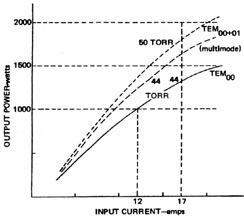
Fig. 8 When a large negative potential is applied to the emitter, electrons leave it and travel toward the anode, gaining speed and kinetic energy. The foil window is then enough to allow most of these electrons to pass through. Each energetic electron travels through the gas mixture, ionizing large numbers of atoms. Electrons liberated by this process are accelerated by the electric field of the sustainer electrodes and transfer energy to the N2 molecules through collisions. The process continues as long as the electron beam is present, but ceases when the electronic source is off. Thus, controlling the relatively low current of the emitter controls laser current and output power. The primary disadvantage of E-beam ionization is the added expense of the vacuum and high-voltage systems. A significant cost reduction may be achieved with the use of anode-pad excitation shown in Figure 9. One laser employing this configuration uses 54 anodes 0.5 inch wide and 4 inches long. Each anode has its own ballast resistor to limit current. The cathode is a metal bar above the anode and slightly upstream. Practical operating pressures in such a system are limited to 50 torr. Figure 10 shows output power as a function of current for the above laser.
Fig. 9
Fig. 10
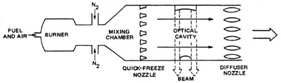
The Gas Dynamic Laser The last type of CW CO2 laser to be discussed is shown in Figure 11. It requires no electrical excitation and is essentially a rocket engine with an attached optical cavity. The fuel may be cyanogen (C2N2) or carbon monoxide (CO) among others. Typically, fuel is burned in a combustion chamber at a temperature of ~1400 ° K and a high pressure of > 15 atmospheres. The hot gases travel downstream to a mixing chamber, where additional nitrogen is added. Small quantities of H2O or He also may be introduced at this point. Most of the CO2 molecules are excited by the N2 to a high vibrational state. (Typical gas ratios are: 90% N2, 9% CO2, 1% H2O.)
Fig. 11 The gas mixture next flows through a quick-freeze nozzle (so called because it lowers the temperature and "freezes in" the excited population inversion) which reduces gas pressure to about 50 torr and increases the velocity to several times the speed of sound. The expansion and reduction in pressure cool the gas very quickly. CO2 molecules in the upper lasing level (001) remain there, and some molecules in higher energy states drop to the (001) level. All other energy states are depopulated by the rapid cooling of the gas. (Thus, inversion is achieved.) The H2O or He aids in this depopulation. The gas travels through the optical cavity at supersonic speeds and lasing occurs, dropping the CO2 molecules to the (100) state. The gas is exhausted through another set of special nozzles, diffusers, which slow the gas further and match its pressure to ambient conditions. The gas dynamic laser carries the gas transport principles to its limit—each molecule is used once and thrown away. The > tens of kilowatts produced by such lasers generally require the use of unstable resonators and aerodynamic windows. Other types of molecular gas can be used in gas dynamic lasers. Waveguide CO2 Lasers The opposite of the size extreme from the gas dynamic laser is the waveguide CO2 laser. These are small lasers with typical lengths of 5 to 25 cm and bore diameters as small as 1 mm. Bores of these laser tubes are made of beryllium oxide. The hollow dielectric structure acts as a waveguide for the CO2 laser light producing a low-loss optical cavity. The small bore diameter results in good gas cooling efficiency and high gain. Waveguide CO2 lasers produce output powers of around 0.2 W/cm of tube length. Thus, a laser only 10 cm long can produce an output power of 2 watts. Waveguide CO2 lasers are rugged and dependable and are attractive for applications in communications, pollution monitoring, and optical ranging systems. Design of a Class I CO2 Laser Output power of a typical Class I CO2 laser operating in an optimized condition with respect to gas ratio, pressure, and tube current may be calculated if design data on the optical cavity and laser tube are known. This section presents a set of equations that may be used to determine approximate maximum output power of a Class I CO2 laser. The equations are based in part on experimental observation and are presented without a theoretical development. An example problem is included to illustrate use of the equations. Description Of Lasers The laser to which these design equations apply is the most common type of CO2 laser. Design features include: · Flowing gas system. · Water-cooled tube. · Long-radius hemispherical optical cavity (plane spherical) with a mirror separation less than or equal to twice the radius of curvature of the spherical mirror. · Beam diameter-limiting aperture located near (or very near) the spherical mirror surface.
Design Equations The following can be used to determine output power of a CO2 laser:
Equation 1 gives the power of the laser during optimum operation if active length, gain coefficient, loss, and transmission of the output coupler are known. Transmission of the output coupler and the active length may be obtained from system data sheets or can be measured. The gain coefficient is given by Equation 6 in cm-1 where tube diameter D is measured in cm. Loss is calculated using either Equations 2 or 5 as described below. Equation 2 gives the diffraction loss of a Gaussian laser beam of radius w when it passes through an aperture with a radius r. In this case the radius r is the radius of the cavity aperture, when is located near the spherical mirror, and beam radius w is defined as the spot size of the beam on that mirror. Size of the Gaussian laser beam inside the optical cavity depends upon curvature and separation of the mirrors and the wavelength of the light. Size of the aperture does not affect size of the beam for any given laser mode. It determines only the loss for that mode. Equations 3 and 4 give spot sizes of the TEM00 mode on the flat and spherical mirrors for a long-radius hemispherical cavity. Equation 5 is the result of substituting the value for ws from Equation 4 into the expression for diffraction loss in Equation 2. Thus, Equation 5 gives the diffraction loss for any long-radius hemispherical laser cavity with its limiting aperture near the spherical mirror. This is usually the case, because the beam has its maximum diameter on the spherical mirror. In CO2 lasers the limiting aperture is usually the bore of the laser tube. Decreasing the bore increases gain because of more efficient gas cooling, but it also increases diffraction loss. Larger-diameter tubes also tend to support higher-order TEM modes. In most Class I CO2 lasers tube diameter is chosen to give a loss of 2% to 15% for TEM00, depending on laser size. If optics of the system are clean, undamaged, and aligned properly, total loss l usually may be assumed to be equal to the diffraction loss l d. If damaged optics or additional optical components are present, the loss they introduce must be added to the diffraction loss.The following example illustrates use of Equations 1 through 6 in determination of output power and beam diameter of a CO2 laser.
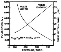
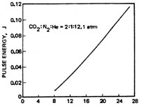
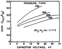
These equations may be used as the basis of a computer program that will plot variations in output power as any laser cavity parameter is varied. Types of Pulsed CO2 Lasers Any CO2 laser discussed thus far, except the gas dynamic laser, may be operated in a pulsed mode by applying electrical pulses instead of dc excitation. In fact, pulsed operation is preferred to CW operation for several industrial applications. Experiments with coaxial systems resulted in higher-energy pulses of shorter duration as gas pressure was increased. This led to the development of several types of pulsed CO2 lasers operating with transverse excitation at atmospheric pressure. They are referred to as transverse excited atmospheric lasers, or simply TEA lasers. All TEA lasers share several common characteristics. One of the most important is the use of relatively short discharge paths to excite large volumes of gas at atmospheric pressure. This short, high-volume discharge has two advantages. First, it makes atmospheric pressure operation possible at easily obtainable voltages (~20 – 50 kV as opposed to MV for axially-excited systems). Second, it lowers effective resistance of the discharge by several orders of magnitude. This means that a large amount of energy can be introduced for maximizing operating efficiency, because the CO2 molecules should be excited in a time that is short compared to the lifetime of the upper lasing level (~10 msec at 1 atm). Operation at pressures of 1 atm or above is desirable to achieve the maximum in both peak power and average power. Energy stored per unit volume in the CO2 gas increases linearly with gas pressure. Thus, greater values for energy per pulse may be achieved at higher pressures. The number of collisions leading to de-excitation of the CO2 (100) level also increases with increased pressure. This provides better gas cooling and means that higher pulse repetition rates are obtainable at higher pressures. As both energy per pulse and maximum pulse repetition rate increase linearly with operating pressure, maximum available average power increases with the square of the pressure. Figure 12 shows that the pulse energy increases with increasing values of total gas pressure, while pulse duration decreases with increasing pressure. From this, it can be seen that the peak power obtain in a TEA laser also increases approximately as the square of the operating pressure, the same result concluded for the average power. The increase in pulse energy as a function of stored electrical energy is illustrated specifically in Figure 13.
Fig. 12
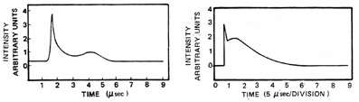
Fig. 13 Small-signal gain in TEA lasers also increases with stored energy. This is shown in Figure 14 for several gas pressures. Finally, Figure 15 displays typical oscilloscope traces for a TEA laser pulse. Notice that, for both cases, two pulses are actually shown. An initial high-peak, short-duration pulse is followed by a second pulse component for much lower peak power and greater duration. The observed spike is about 0.4 m sec wide, and is the result of direct excitation through electron collisions with CO2 molecules. The second pulse, ~2-m sec duration, can be advanced or retarded in time and its amplitude changed by changing the concentration of N2 gas. In fact, the second pulse is not observed at all when N2 is not present in the gas mixture. Hence, this pulse is attributed to subsequent excitation of CO2 molecules by collisions with excited N2 molecules.
Fig. 14
Fig. 15
Pin Lasers Figure 16 is a schematic diagram of a PIN CO2 laser. This design derives its name from its cathode, which consists of a series of resistively (ballasted) loaded pins. The resistors are necessary to produce a uniform discharge throughout the gas volume. A laser of this type, 1 meter in length, typically will have 200 resistors of 1000 ohms each. The anode is a metal bar with a separation of about 3 cm from the cathode pins. With a charging voltage of 50 kV on a 0.01- m F capacitor and an active volume of 100 cm3, laser pulses of 1.5 joules may be obtained.
Fig. 16 A variation of this design may be used to produce a more nearly circular active volume. In this configuration, the anode consists of a spiral of pins opposing the cathode spiral.
Strip-Cathode Lasers This type of laser is shown in Figure 17. The anode consists of a flat metal plate. The cathode is a series of metal strips separated by glass capillary tubes. Inside each tube is a trigger electrode. These secondary electrodes are used for preionization of the gas and are connected to the anode. Distance between the cathode strips and trigger electrodes is quite small, ~2 mm. Thus, when a discharge pulse is applied to the cathode, the gap between a cathode strip and trigger electrode experiences the full cathode-to-anode voltage (~20 kV), that is, an electric field of some 105 V/cm. The resulting emission of electrons from the cathode forms a sheath around it and ensures a uniform discharge between cathode and anode. Thus, a double-discharge takes place. Other double-discharge arrangements include a grid of fine wires used for the anode with a flat bar cathode and a single flat trigger electrode for preionization.
Fig. 17
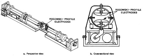
Rogowski-Profile Lasers Figure 18 shows a typical CO2 laser employing Rogowski-profile electrodes. These are long metal bars with a somewhat crescent cross-sectional shape. The center portion of the electrodes is almost flat. Near the edge, the radius of the curvature increases gradually such that the electric field is uniform across most of the interelectrode spacing. (Remember that the electric field is greater near sharp points on conductors.)
Fig. 18
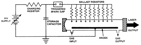
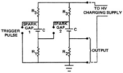
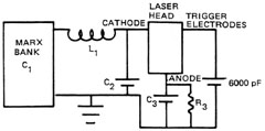
A small trigger wire is stretched along each side of the Rogowski electrode pair. These electrodes (sometimes called "preionizers") create a sheet of ionization near the cathode when a high-voltage pulse is applied to them. This results in a uniform discharge across the active volume. In some commercial Rogowski-type CO2 lasers, the cathode is shaped from a sheet of thin metal containing thousands of tiny holes. The preionizer consists of a screen or a series of wires and is located inside the curved surface of the electrode. In practice, this configuration approximates the effect of the electron beam discussed earlier. In this case, however, it only triggers the discharge, primarily by generating UV light; it does not sustain it. Figure 19 shows a Marx bank pulsed power supply commonly used for both strip-cathode and Rogowski-profile CO2 lasers. This is a two-stage bank and is capable of producing an output pulse at twice the charging voltage. The capacitors are charged in parallel. A trigger pulse delivered to the first spark gap causes it to ionize and creates a short circuit. This produces an overvoltage on the second gap, and it breaks down also. The result is that the capacitors are connected in series by the shorted gaps. Higher voltages may be obtained by simply adding more stages to the Marx bank. Figure 20 shows the circuit necessary to deliver voltage to both the trigger and main electrodes.
Fig. 19
Fig. 20 Rogowski-profile lasers are the most common commercially available type of TEA laser because of their higher efficiencies and output powers. Larger versions are capable of one pulse per second at several hundred joules per pulse. They may be operated at higher pulse rates, but this results in lower energy per pulse. The same systems used for CO2 also may be used with CO, HF, or N2O. Because of the high peak powers produced (typically 300 MW), the larger systems employ unstable resonators.
E-Beam Ionized Pulsed CO2 Lasers These are the giants of the pulsed gas lasers and usually are found only in research facilities such as Los Alamos National Laboratory. Their operation is very similar to that of the E-beam ionized CW lasers discussed, but there are several important differences. · They operate at or above atmospheric pressure. · Their main power supplies are designed to deliver high-current pulses rather than to sustain CW operation. · Gas flow rates are usually low, if the gas flows at all. Often, the gas is simply changed periodically. E-beam ionized pulsed systems are usually used as optical amplifiers to produce extremely high peak powers.
Intracavity Devices for CO2 Lasers CW CO2 lasers usually operate on a single P-branch transition within the 10.6- m m region. The output of pulsed CO2 lasers usually has a duration of several hundred nanoseconds and includes about 90 lines. Unless some kind of tuning is used, lasing occurs on both the P- and R-branches of the 10.6-m m regions. Several methods may be used to alter those output characteristics.
Spectral Tuning Spectral tuning may be accomplished in either CW or pulsed molecular gas lasers by use of a diffraction grating. The grating replaces the high-reflectance mirror and is tilted to reflect the desired wavelength back through an amplifier tube. Both pulsed and CW CO2 lasers may be tuned to any one of 90 separate lasing lines between 9.1 and 11.0 m m.
Q-Switching Q-switching of CW molecular lasers is most commonly accomplished by rotating the high-reflectance mirror at about 20,000 r/min. This produces output pluses of about 50- m sec duration with peak powers of several thousand times the CW power of the laser. A method called "reactive Q-switching" (a form of acousto-optics) also has been used on CW CO2 lasers. This technique involves translating one of the cavity mirrors along the optical axis at a speed ~16-30 cm/sec by a piezoelectric transducer. This changes the frequencies of the cavity modes, allowing several modes to lase briefly as they sweep across the laser gain curve. High pulse repetition rates (~30-60 kHz) can be obtained with reactive Q-switching, with pulse widths of about 1 m sec and an average output nearly equal to the CW output.Q-switching of low-power pulsed CO2 lasers has been accomplished by the use of acousto-optic devices in the cavity. These devices are unsuited, however, for use with high-gain systems. Gaseous saturable or bleachable absorbers such as sulphur hexafluoride (SF6) also have been used with limited success. Q-switching of high-power pulsed molecular lasers is rare, as no really good inexpensive electro-optic devices have been developed for that purpose.
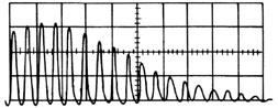
Mode Locking Mode locking of either CW or low-power pulsed CO2 lasers may be accomplished with an acousto-optic (AO) device. This technique results in a train of short, high-power pulses as shown in Figure 21. SF6 cells have been used as mode lockers for pulsed systems, but are not usually as effective as AO devices.
Fig. 21
Summary CO2 lasers are popular for a variety of applications in both CW and pulsed models. CW CO2 lasers are commercially available in four types. The smallest is the waveguide laser with lengths as short as a few centimeters and output powers of from less than a watt to a few watts. The most common type of CO2 laser is one in which the optical axis, current flow, and gas flow are all in the same direction and gas cooling is achieved by collisions of helium atoms with the cooled tube walls. These are available in powers up to about one kilowatt. An improvement on this design uses larger tubes, a high gas flow rate, and heat exchangers for gas cooling. These produce output powers of a few kilowatts. The largest commercial lasers are multikilowatt systems in which gas flow, current flow, and optical axis are all in different directions. The largest CW CO2 lasers are chemically powered gas dynamic lasers under experimental development for defense applications. Pulsed CO2 lasers that operate at atmospheric pressure are available in several sizes with several electrode configurations. The most popular is a Rogowski-profile electrode for uniform distribution of the charge through the gas volume.
1. Explain the primary factor limiting output power of a Class I CO2 laser and the method of overcoming this limitation in Class II and Class III CO2 lasers. 2. Construct a table that compares the characteristics of the following optical materials used in CO2 lasers. Also explain the practical applications of each material and why it is chosen for each application.
3. Draw and label diagrams showing the following laser systems:
4. Explain how CO2 molecules are excited to the proper energy level in an electron-beam excited laser. 5. Draw and label a diagram showing elements of a gas dynamic laser, and describe its operation. 6. Draw and label diagrams of the following types of TEA CO2 lasers:
7. Explain how and why peak and average powers of a repetitively-pulsed TEA CO2 laser vary with gas pressure. 8. Calculate diffraction loss, beam diameter to
9. Use information and design equations given in this module to design CO2 lasers of the powers indicated below. In each case assume that: (cavity length) = (active length) ´ (1.1). For each laser, determine: cavity length, active length, tube bore diameter, radius of curvature of HR mirror, transmission of output coupler, beam diameter on both mirrors, and actual calculated optimum output power.
10. Use laser parameters given in Example A as a specific case to construct graphs showing variation of output power as other parameters are varied. In each case, assume that all parameters are fixed at the value stated in Example A except for the parameter specified as variable. Draw a separate graph of output power versus each of the following:
11. List at least four manufacturers of CO2 lasers and the laser systems available from each.
CO2 laser with removable mirrors (complete operational system) Optical power meter for measuring laser output power CO2 laser beam display screen compatible with laser power level UV lamp for illumination of screen HeNe laser Glass flat of the same dimensions as the CO2 output coupler CO2 laser safety goggles
Alignment of a CO2 Laser Students should be familiar with operation of the CO2 laser used in this laboratory before beginning the laboratory exercise. This laboratory is intended to follow that of Module 3-8, "Energy Transfer in Molecular Lasers." Students should read all procedures and the data section before beginning. Ensure that all personnel are wearing protective eyewear during laser operation. 1. Review CO2 operational procedures in the laser equipment manual and the laboratory procedures from Module 3-8. 2. Place power meter detector head to intercept the CO2 laser beam at a distance of approximately one meter from the laser output aperture. 3. Following standard operation procedures and all safety precautions, bring the laser into operation at its maximum operating power. 4. Record all pertinent data on system condition and parameters and the initial maximum CW output power. 5. Allow the system to operate for five minutes, and record output power. 6. Turn off the laser, following standard procedures, disconnect the main power, and discharge all capacitors in the power supply. 7. Bring the laser tube to atmospheric pressure and remove both laser mirrors. Wrap mirrors in clean lens tissue and place them in a protected location. 8. Change positions of each adjustment screw on both mirror mounts to misalign the laser. 9. Place the HeNe laser on an adjustable table in line with the optical axis of the CO2 laser at a distance of about one meter from the CO2 laser output aperture. Align the HeNe laser through the bore of the CO2 laser tube. 10. Make two apertures from index cards and attach them to the ends of the CO2 laser tube. Each should have a centered hole just large enough to allow the beam to pass through without blocking a significant portion of the edge of the beam. Place a similar aperture on the output of the HeNe laser. 11. Adjust the two lasers so that the HeNe beam travels exactly down the center of the CO2 laser tube. Neither laser should be moved from the aligned position until the alignment procedure is complete. 12. Remove the rear cardboard aperture from the laser tube and mount the HR mirror in its mount. Clean the mirror only if necessary. Follow procedures in the laser manual. 13. Align the HeNe beam reflected from the HR mirror to be centered on the HeNe output aperture. This ensures that the HR mirror will be aligned with the axis of the laser tube. Its adjustments should not be changed until the alignment procedure is complete. 14. Remove the front aperture from the laser tube and install a glass flat in place of the output coupler. Align the reflection of the HeNe beam from the flat to be centered on the HeNe output aperture. 15. Evacuate the laser tube while closely observing shape and location of the reflected spots on the HeNe laser output aperture. If location of the spots is different after tube pressure stabilizes at operating pressure, an instability is indicated in the mirror mounts. Such problems do not normally occur and this step is not a part of most alignment procedures. 16. Bring the laser tube back to atmospheric, and replace the glass flat with the output coupler. Align the reflected HeNe beam from the output coupler so that it is centered on the HeNe laser output coupler. This does not necessarily mean that the CO2 laser will be aligned, only that it will be very close. This technique results in small misalignments due to any wedge in the output coupler substrate. 17. Place the CO2 laser beam display screen between the HeNe laser and the CO2 laser to intercept and display the CO2 laser output beam. 18. Operate the CO2 laser and observe output. If no beam is present, lasing may be achieved by small adjustments of both horizontal and vertical adjustments of the mirror mount. Adjust the output coupler mount to achieve the "best looking" output spot on the screen. 19. Remove the HeNe laser and place the power meter detector head to intercept the CO2 laser beam. 20. Remove the display screen and measure output power of the laser. 21. Make small adjustments of output coupler alignment to maximize power. Note any increase. 22. Make small adjustments in HR mirror alignment to achieve maximum output power. Note any increase. 23. Set all laser parameters for the same values as the power reading before alignment, and record final maximum power of the laser. 24. Replace the display screen in the beam and observe beam shape. Misalign one mirror slightly and observe changes in beam shape. Sketch the shapes resulting from slight and large misalignments of each mirror on each axis. 25. Realign the CO2 laser for its maximum power and shut the system off. 26. Return all equipment to its original condition and secure the lab. LABORATORY REPORT Each student should prepare a report of the alignment procedure of the laser, including any problems encountered. The report should include appropriate sketches that illustrate steps in laser alignment and appearance of the output laser beam on the display screen for good alignment and for misalignment.
Anderson, John D., Jr. Gas Dynamic Lasers - An Introduction. New York: Academic Press, 1976. Duley, W.W. CO2 Lasers—Effects and Applications. New York: Academic Press, 1976. O’Shea, Donald C.; Callen, Russell W.; Rhodes, William T. Introduction to Lasers and Their Applications. Reading, MA: Addison-Wesley Publishing Co., 1977. Pollack, M.A. "Molecular Gas Lasers," Handbook of Lasers. R. J. Pressly, ed. Chemical Rubber Co., 1976. Ready, John F. Industrial Applications of Lasers. New York: Academic Press, 1978.
|
||||||||||||||||||||||||||||||||||||||||||||||||||||||||||||||||||