| This version reflects the comments of the core participants as reviewed and incorporated in accordance with CORD's FIPSE-supported Curriculum Morphing Project. | |||||||||||||
MODULE 3-6 Ion lasers are gas lasers in which the stimulated emission process occurs between two energy states of an ion. The excitation mechanism of such a laser first must supply the necessary energy to remove an electron from the lasing atom to produce the ion, and then must supply additional energy to raise the ion to the appropriate excited state. These large input energy requirements result in low efficiencies for essentially all ion lasers. Two types of ion lasers are in common use. One type uses helium as a buffer gas for achieving lasing of ionic metal vapors. The most common laser of this type is the helium-cadmium laser, which produces a few milliwatts at 441.6 nm and 325 nm. Several other metals may be used in similar systems. On the other hand, metal vapor ion lasers are typically low-current, high-voltage devices similar in many ways to HeNe lasers, although they are more complex because they require close temperature and current control. Although these metal ion lasers fall into the category of "ion lasers," they will not be discussed in this module. In the more important class of ion lasers are those employing noble gases as the lasing medium. Argon lasers are by far the most numerous and important of this group, but krypton ion lasers are also in wide use. Xenon lasers also may be constructed; several are available commercially, but they are much less common. This module discusses the energy transfer mechanisms responsible for lasing in argon and krypton ion lasers and how these mechanisms affect design, construction, and output characteristics of ion lasers. Topics presented include ion laser energy-level diagrams, plasma tube design, auxiliary equipment requirements, and output characteristics. Argon lasers are used for the primary example because of their great importance and popularity. In the laboratory, the student will operate an argon ion laser and measure some of its output characteristics. A more detailed study of the same system will be accomplished in the laboratory of Module 3-7, "Argon Ion Laser Systems."
Upon completion of this module, the student should be able to: 1. Draw and label an energy-level diagram showing the important energy levels and transitions in an argon ion laser. 2. Explain the process by which an argon atom is excited from the atomic ground state to the upper lasing level. 3. Explain two types of competition between pairs of lines in the argon laser output spectrum. Give an example of each type of competition, and describe how this affects the multiline output of the laser. 4. Explain the de-excitation process that lowers the population of the lower lasing levels in the argon ion laser. 5. List and explain four critical factors that must be considered in ion laser tube design. 6. Draw and label a diagram of a segmented graphite-base argon laser tube and explain how its construction reflects the above considerations. 7. Draw and label a diagram of a beryllium oxide-base argon laser tube and explain it. 8. Compare graphite-base tubes to Be0 tubes. 9. Explain reasons for the following design features of argon laser tubes:
10. Explain the dependence of the output power of an argon laser on each of the following parameters:
11. Explain the type of optical cavity typically used in an ion laser and why it is chosen. 12. Explain how various wavelengths are selected for single-line operation in an argon laser. 13. Use procedures and materials listed in this module to operate an argon ion laser and measure its output power on all lines and on each line separately.
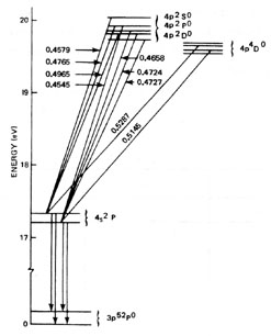
Energy Transitions in Ion Lasers Ions used in ion lasers are atoms from which one or more of the electrons have been removed, producing an ion with a net positive charge. Such an atom is ionized by adding sufficient energy to free one of its electrons. This energy may be added in a single collision that liberates the electron from the atom, or it may be incrementally added in small steps, increasing the energy state of the atom each time until the ionization energy is reached and an electron is liberated. The minimum energy of the atom with one electron missing is called the "singly-ionized ground state." Energy levels for ions have structures similar to those of neutral atoms. If enough energy is added to the ion, it will lose a second electron and become "doubly ionized," and so forth. Noble gas ion lasers typically produce lasing between two states in the singly ionized atom. To place the ion in the proper state, the excitation mechanism must provide sufficient energy to ionize the atom and to raise the ion to the proper excited energy state. This module discusses how this is accomplished in noble gas ion lasers with argon as the example. Argon Ion Energy-Level Diagram Figure 1 is an energy-level diagram showing the most important energy levels and transitions involved in operation of an argon ion laser. Energy levels in this diagram are identified by spectrographic notation, and principal lasing transitions are labeled with their wavelengths in microns. Energy is given in electron volts relative to the ionic ground state, which is 16 eV above the neutral atom ground state. (That is, 16 eV is required to remove one of the electrons from the argon atom.) A great many other energy states and transitions are possible for argon ions. Only those of importance in the lasing process are shown. The energy-level diagram of krypton ion lasers is similar and the processes described below also apply to krypton lasers.
Fig. 1 Excitation in Ion Lasers Excitation of atoms from atomic ground state to the upper lasing level of the ion in an argon ion laser requires approximately 36 eV of input energy to the atom. This energy is delivered in the form of electron collisions. Each electron collision imparts 2 to 4 eV to the atom, moving it upward from one atomic energy state to another. Because lifetimes of these atomic states are short, the atom must experience a collision quickly after each upward transition or it will emit a photon and drop back toward the ground state. Thus, a high current density is necessary to provide the required collision rates, and increasing current density in the bore of the laser tube increases the output power. The accumulated energy of successive electron collisions eventually places the ion in an energy state that is the upper state for one of the lasing transitions or in some higher energy state. These ions in the upper lasing level produce the population inversion necessary for lasing. Ions in higher energy states quickly drop to one of the upper lasing states by releasing one or more photons, further increasing the population of that state. Lasing occurs as the ion drops to one of two lower energy states. Lasing Action in Ion Lasers The gain for any one of the possible laser lines in an ion laser depends upon the population inversion between the upper and lower lasing levels for that line. Lines with the greatest population inversions have the greatest gain and, therefore, the highest output power. A dispersing or tuning prism can be used inside the laser cavity to allow only one wavelength to lase at a time. From nine to twelve lines may lase in a typical argon laser. Table 1 lists the strongest lasing lines for both argon and krypton. Table 1. Representative Outputs of Ion Lasers.
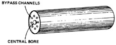
If the tuning prism is omitted and laser mirrors are aligned to allow lasing at any wavelength in the overall gain region, several lines will produce laser output at once. In argon lasers, the five strongest lines usually will lase at once, although in lower-power models one or two of these may be missing. The other lines will not lase as they are in competition with stronger lines. Two types of line competition are illustrated in Figure 1. The greatest population inversion and output power occur for the 488-nm and 514.5-nm lines. These lines share the same lower lasing level. When either or both of these lines produce laser output, they place ions in the lower lasing level, thus increasing its population significantly. Because other lines with this same lower level always have lower populations in their upper levels than the stronger lines, the increase in the lower-level population destroys their population inversions and they will not lase. These weaker lines produce laser output only if the stronger lines are suppressed. The 488-nm and 514.5-nm lines have this same competition, resulting in greater power for either if the other is suppressed. Another competition situation is illustrated by the 476.5-nm line and the 454.5-nm line. They have the same upper lasing level and different lower levels. Thus, they are in competition for the same excited ions, and the one that lases will be the one with the lowest population in the lower lasing level. Thus, unless the 476.5-nm line is suppressed, the 454.5-nm line will not lase. Similar situations exist in the energy levels of krypton ion lasers, and they also may be operated either on one line at a time or on several lines at once. A unique feature of krypton lasers is that, with the proper mirrors, they will lase on four lines that are red, yellow, green, and blue in color. This produces an output beam that is white in appearance and is uniquely suited to laser light shows, laser imaging systems, and potentially suited for laser television. De-Excitation in Ion Lasers When lasing has occurred, the ions drop from the lower lasing level to the ionic ground state by emission of a photon with a wavelength of about 70 nm. This transition occurs very rapidly, maintaining a low population in the lower lasing levels. The 70-nm wavelength is in the vacuum ultraviolet and is absorbed by the laser tube exposed to this radiation. The ion may be excited directly from the ionic ground state back to the upper lasing levels by electron collisions, but it usually captures an electron and drops further in energy before being re-excited, although it may not drop all the way to the neutral atom ground state. At any given moment, only a small percentage oft he argon atoms are ionized. All waste energy from the laser discharge is absorbed into the laser tube structure. As the efficiency of a typical argon laser is only about 0.05%, a 5-watt laser produces 10 kilowatts of waste heat in the laser tube. The limitation on the output power of the laser is the efficiency with which this heat can be removed. An increase in internal temperature does not degrade the lasing process as in solid-state and molecular gas lasers, but at some point the laser components are degraded by overheating. Ion Laser Plasma Tube Design Several materials and designs have been employed for ion laser tube construction. All of these reflect the necessity for the tube to withstand high currents and internal temperatures. The following are general considerations for ion laser tube construction: 1. The tube must withstand thermal loads on the order of 500 W/cm length produced in large part by ion bombardment. High-energy ions will erode most bore materials rapidly. 2. Positive ions are attracted to the cathode, resulting in unequal gas pressures along the bore. This greatly reduces laser power and may stop lasing completely. Gas bypass channels must be provided to equalize the pressure for proper performance. 3. Electrodes must be designed to withstand the discharge current (typically 50 to 200 amperes) and must be resistant to electron and ion bombardment. 4. Gas pressure is continuously reduced by ions embedded in the inner surface of the tube. A provision for adding gas is required in most ion lasers. Early ion lasers used tubes with water-cooled quartz bores. These were unacceptable because ion bombardment quickly eroded the bore, reducing laser efficiency and destroying the laser tube in a hundred or so hours of operation. Another early design used a flowing gas system and a bore consisting of tungsten segments with a central hole for the discharge and beam. This design had a longer lifetime but was inefficient and undependable. Extensive research led to development of two major types of ion laser tubes that are used in all argon and krypton lasers today. Graphite-Bore Tubes Figure 2 illustrates components and design of an ion laser tube with a segmented graphite bore. Graphite is one of two materials identified that can withstand the temperatures and ion bombardment of the ion laser discharge without significant erosion. The envelope of the tube is made of fused quartz to withstand the high temperature differentials between the graphite segments and the cooling water that flows across the outer wall of the envelope.
Fig. 2 Each bore segment has a thickness of less than a centimeter, a hole in the center for the beam and discharge, and a series of holes around the central opening to provide for gas bypass. The segments are stacked together inside a quartz tube to form the bore of the laser tube, and the quartz envelope is shrunk to hold the segments in place. In some models, segments are supported on sapphire rods with insulators between them. Central segments have a constant bore diameter. End segments have increasing bore diameters to avoid aperturing the beam more than necessary. The discharge is contained within the graphite segments, and they transmit waste heat to the quartz envelope. Beryllium Oxide-Bore Tubes A more recently developed tube that is in extensive use is a design using beryllium oxide (Be0) as a bore material. One segment of such a tube is shown in Figure 3. These are typically a centimeter in diameter and several centimeters long. The tube is formed by sealing a series of such segments together with a ceramic. One end of the tube is sealed to a quartz section containing the cathode and providing a ballast volume and gas fill port. The other end terminates in a metal section that serves as the tube anode and output water port. A quartz extension beyond this holds the Brewster window and is attached to a gas bypass tube leading back to the cathode end of the tube. The Be0 segments and the cathode section are enclosed in a quartz water jacket. The completed tube is shown in Figure 4.
Fig. 3
Fig. 4 Both graphite and Be0 tubes are in common use, but Be0 is becoming more popular because it offers the following advantages: · Longer tube lifetime. · Higher thermal conductivity, resulting in more uniform thermal conduction and better heat transfer to the cooling system. · Longer operation without need for gas refill. · More rugged structure. · Faster attainment of full power and higher stability. · Reduced erosion of the bore and less gas cleanup problems. · Smaller system weight and power requirements for the magnet (solenoid), resulting in an increase in laser output power for the same power input to the system.
Electrode Design The anode of the laser tube is subjected to bombardment by the electrons of the tube current. Because the electrons have very little mass and, thus, low kinetic energy, they do not cause a significant heating effect of the anode. The anode of the graphite tube is a metal ring inside the quartz envelope. The metal water port serves as the anode of the Be0 tube. In both cases, the cathode is a coiled tungsten ribbon coaxial to the optical axis. A filament transformer provides a current through the cathode that heats it to an orange glow and produces a cloud of thermally-emitted electrons around the cathode. Positive ions attracted to the cathode encounter this electron cloud, capture an electron, and become neutral atoms. Their kinetic energy is then dissipated by collisions before reaching the cathode. If the electron cloud is not present, the high-speed positive ions strike the cathode directly and quickly destroy it. Other Tube Features Ion laser tubes typically incorporate several other design features to ensure proper operation. An increase in temperature of the gas in the small active volume results in large pressure changes that reduce laser output. This is prevented by connecting the tube bore to a larger-volume ballast at lower temperature. Thus, gas from the bore expands into this volume when heated and the pressure changes very little. Most tubes are also equipped with a pair of valves that are used to add a measured amount of gas to the laser tube as necessary to maintain proper operating pressure. A thermocouple vacuum gage usually is included to measure tube pressure. The plasma tube is surrounded by a solenoid that produces a uniform magnetic field along the optical axis in the bore of the tube. Charged particles moving along the lines of magnetic force are unaffected. Those moving at an angle to these lines are forced into a spiral path around the magnetic field lines. This serves two purposes. First, ions that are headed away from the center of the tube are bent back toward it, thus reducing ion bombardment on the bore walls and reducing corrosion and heat load. Second, the spiral path means that electrons sweep out larger areas in moving from one end of the tube to the other and, thus, are likely to have more collisions than if they took a straight path. Operating Parameters of Ion Lasers Ion lasers may be operated either with several laser lines in operation or on a single line at a time. In either case, output power depends on tube current, gas pressure, and magnetic field strength. This section discusses how these parameters affect laser output power.
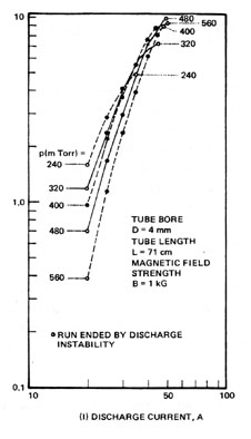
Dependence of Laser Output on Tube Current The most general expression for the output power of an argon ion laser indicates that the power increases approximately with the square of the current density. (Current density is the current in amperes divided by area of the tube bore in square centimeters.) One consequence of this relationship is that smaller bores produce higher powers for the same current values. Thus, ion lasers are constructed to have the smallest bore diameters possible without introducing excessive diffraction loss or erosion. For a specific argon laser, output power varies roughly with the square of the tube current near the high-power end of its output range. Thus, doubling the current would produce four times the output power. At lower power levels, output power typically increases even more steeply. Figure 5 shows output power-versus-current curves for an argon laser in multiline operation at several gas pressures. The slope of the power-versus-current curve varies somewhat with pressure, but in all cases a small current increase produces a significant output power increase. Thus, ion lasers are designed and rated to operate at the highest possible currents that the tube can withstand for its rated lifetime.
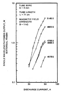
Fig. 5 Figure 6 shows output powers of several ion laser lines as functions of tube current when a prism wavelength selector is used inside the laser cavity.
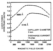
Fig. 6 Dependence of Laser Output on Gas Pressure Argon and krypton lasers may be operated at gas pressures from 250 to 500 millitorr, but the best operation is usually in the range of 300 to 350 millitorr. Specific systems are designed to operate best at a specific gas pressure, and the laser power supply is matched to tube characteristics at that pressure. Changes in tube pressure result in variations in output pressure as indicated in Figure 5. Gas pressure drops as gas is absorbed inside the tube, and additional gas is required periodically. If gas pressure is too low or too high, electrical characteristics of the tube may become incompatible with the power supply, resulting in failure of the tube to ignite or in unstable operation. Gas pressure in an ion laser typically increases after the laser reaches operating temperature. The increase may continue for several hours if the laser has been out of operation for a long period of time. Thus, gas should never be added too hastily if the pressure is low when the laser is turned on. A common occurrence for an ion laser that has been idle for several months is the addition of gas to bring pressure up to the specified operating point at turn-on, resulting in a serious overpressure after a few hours of operation. The only way to lower the pressure is to run the laser or, in extreme cases, to reprocess the tube. Dependence of Output Power on Magnetic Field Strength Figure 7 shows variations in output power of an argon laser at the two strongest laser lines as magnetic field strength is varied. If there is no field, current density in the center of the bore is reduced and more energy is being lost through collisions with the walls of the tube. An increase of magnetic field strength increases current density and output power.
Fig. 7 When a gas is subjected to a strong magnetic field, each of its energy levels splits into several closely-spaced levels. This is called the Zeeman effect and is proportional to the strength of the magnetic field. The magnetic field in an argon laser results in a broadening of the laser gain curve that is proportional to the applied magnetic field strength. At field strengths below about one kilogauss, this produces a broadened output spectrum with more cavity modes and higher output power. Above about one kilogauss, the gain curve becomes so broadened and flat that its edges fall below the lasing threshold and the output power and spectral lines will both begin to drop. Each laser line has an optimum magnetic field strength. Most argon lasers have a control to adjust the magnetic field strength for optimum operation on each line.
Optical Cavities of Ion Lasers Most ion lasers employ long radius hemispherical optical cavities. A typical 5-watt argon laser has a cavity length of about 1.25 m. The HR mirror is flat, and the radius of curvature of the output coupler is four or five meters. This produces a small beam inside the bore of the laser tube while making optimum use of the active volume. Figure 8 shows transmission curves for the mirrors of a typical argon laser. The HR mirror has a broadband coating that is 99.9% reflective across the entire blue-green portion of the spectrum. The output coupler coating is designed for specific transmissions at specific laser wavelengths to provide the best operation for each laser line. Transmission typically varies from 1% to 4.5% in the spectral output range of the laser.
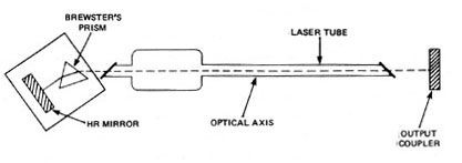
Fig. 8 The tuning mechanism commonly employed to select a single laser line is a prism inside the optical cavity, as shown in Figure 9. The prism is cut so the laser beam strikes it near Brewster's angle on both sides. For a fused quartz prism, the apex angle is 78° . The prism and HR mirror are mounted rigidly together and are tilted as a unit to select various wavelengths. Because the prism refracts each wavelength by a different amount, only a single laser line is in proper alignment at any time.
Fig. 9 A device called an etalon may be included in the optical cavity to limit lasing to a single longitudinal mode. Operation of etalons is described in Module 3-7, "Argon Ion Laser Systems."
Summary The most common type of ion laser is the argon laser, operating in the blue-green region of the visible spectrum. The next most popular ion laser system is the krypton laser, which has output lines across the entire visible spectrum. The two are similar in construction and performance, with the argon system producing higher powers for longer lifetimes. Efficiencies of ion lasers are low because of the large amount of input energy required to ionize atoms and excite them to the proper state. Because power increases roughly with the square of the current density, ion lasers are designed with the smallest bore diameters and highest tube currents possible. The only two materials that are practical for such tubes are graphite and Be0. Argon and krypton ion laser systems are among the most complex and sophisticated on the market. 1. Draw and label an energy-level diagram showing important energy levels and transitions in an argon ion laser. Refer to this diagram in answering Questions 2 and 3. 2. Explain the processes by which an argon atom in the ground state is excited to the upper laser level, and how it reaches the ionic ground state after stimulated emission. 3. Explain two types of competition between laser lines in an argon laser. Give an example of each other than the examples used earlier in the Subject Matter. 4. Explain the reasons for the following design features in ion lasers: a. Gas bypass channels. b. Gas fill valves. c. Hot cathode. d. Magnetic field. e. Be0 or graphite bores. 5. Examine graphite and Be0 laser tubes (or pictures if tubes are not available) and sketch and label each type. 6. List and explain four critical factors that must be considered in ion laser tube design. 7. Explain advantages of Be0 tubes over graphite tubes. 8. Draw the optical cavity of an argon ion laser with a prism wavelength selector, and explain characteristics of each component and the overall cavity. 9. Explain how each of the following affects output power of the laser:
10. Refer to the argon laser power supply and instruction manual and list the function of each control on the power supply front panel. 11. Refer to the argon laser instruction manual and list the operating steps for this laser in order.
Argon ion laser system with optics for mutiline operation and single-line operation Optical power meter compatible with ion laser Argon ion laser instruction manual Beam block Argon laser safety goggles Brewster’s angle prism with stand
In this laboratory, the student will identify components of an argon ion laser, operate the laser safely according to approved procedures in both multiline and single-line modes, and measure output power of each line as a function of tube current. Students should read all procedures before beginning. Identification of Argon Laser Components 1. Prior to the scheduled lab period, major components of the argon laser listed below will be identified and located. Sufficient time will be given for all students to become familiar with the location and identification of these parts. 2. During the scheduled lab period, each student will locate and identify these components in the presence of the lab instructor.
3. The student also will identify and explain each control and indicator on the power supply front panel. Operation of the Argon Laser 1. Read the entire laser operations manual before the lab period begins. 2. Observe all recommended safety precautions during laser operation. Be sure that the laser beam terminates on a beam block or power meter sensor at all times. Observe posted precautions regarding the use of safety goggles. 3. Go through a "dry run" without operating the laser. 4. While the lab instructor observes, operate the argon laser according to approved procedures, explaining each step. This includes the complete shutdown procedure for the laser. (The laser should be operated in initially with all lines in operation.) 5. Following procedures outlined in the laser equipment manual, install the wavelength selector and operate the laser on each output line. 6. Return the laser to multiline operation at the end of the lab.
Measuring Laser Output Power Students should perform this part of the laboratory only after authorization and instruction from the lab instructor. The laboratory consists of making necessary measurements to draw graphs of laser output power versus current and magnetic field strength. In each case, the student will devise a procedure to acquire necessary data, have that procedure verified by the lab instructor, and perform the experiment independently. Following are suggested general procedures that may be employed: 1. Measure output power on all lines as a function of current for three different settings of magnetic field strength. 2. Measure output power of individual laser lines as a function of current at a single magnetic field strength. 3. Measure output power of all lines as a function of magnetic field strength at three different current settings. 4. Measure output power of individual laser lines as a function of magnetic field strength at a single current setting. 5. Operate the laser multiline and use a prism to separate wavelengths outside the laser cavity. Measure the power of each line as a function of current at a single magnetic field strength. Compare results to those obtained in Procedure 2. 6. Return the laser to multiline operation at the end of the laboratory. Each student should prepare a laboratory report on the experiment in measuring laser output power. The report should include procedures used, specifications of equipment items, all pertinent data, and graphs and explanations of results. Bloom, Arnold L. Gas Lasers. New York: John Wiley & Sons, 1968. Bridges, W.B. and Chester, A.N. "Ionized Gas Lasers," in Handbook of Lasers. R.J. Pressley, ed. Chemical Rubber Co., 1971. O’Shea, Donald C.; Callen, Russell W.; Rhodes, William T. Introduction to Lasers and Their Applications. Reading, MA: Addison-Wesley Publishing Co., 1977. Ready, John F. Industrial Applications of Lasers. New York: Academic Press, 1978.
|
|||||||||||||