| This version reflects the comments of the core participants as reviewed and incorporated in accordance with CORD's FIPSE-supported Curriculum Morphing Project. | ||||||||||||||||||||||||||||||||||||||||||||||||||||||||||||||||||||||||||||||||||
| MODULE 3-2 PULSED LASER FLASHLAMPS AND POWER SUPPLIES Most pulsed lasers are powered by pulsed power supplies that deliver electrical pulses to the excitation medium. The most common pulsed lasers are pulsed solid-state and liquid lasers in which a flashlamp is used for optical pumping. Flashlamps are gas-discharge devices with an initial infinite resistance and a negative dynamic resistance. The power supply for such a device usually consists of a capacitor for energy storage and discharge, an inductor for pulse shaping, a high-voltage dc charging supply, and a trigger circuit for ionizing the flashlamp. This module discusses the characteristics of flashlamps for pulsed lasers and the pulsed power supplies used to operate them. Flashlamp characteristics discussed include lamp construction, factors affecting lamp lifetime, and the electrical properties of flashlamps. Two types of discharge circuits are discussed. RLC circuits consist of a single capacitor and inductor, used for shorter pulse durations. Pulse-forming networks consist of several LC sections, used for longer pulses. The characteristics and design equations for both types of circuits are explained. The discussion also includes descriptions of external lamp triggering and series injection triggering. In the laboratory, the student will construct RLC and PFN circuits from components and will measure the current pulse to the lamp and the output optical pulse.
Upon completion of this module, the student should be able to: 1. List the three basic elements of a pulsed power supply for flashlamp operation, and describe the function of each element. 2. Explain two mechanisms that lead to lamp explosion and three mechanisms that result in long-term degradation of the optical output from a lamp. 3. Use graphs given in the text to determine the explosion energy of a lamp and the lamp lifetime, given lamp size, pulse duration, and electrical input energy to the lamp. 4. Given the discharge length of a gas-filled lamp and the pulse duration, estimate the resistivity and calculate the lamp resistance. 5. Draw and label curves showing the discharge current of a flashlamp circuit as a function of time for overdamped, underdamped, and critically damped operation. Explain problems associated with overdamped and underdamped operation. 6. Given lamp resistance, pulse duration, and input electrical energy for a flashlamp, design an RLC discharge circuit for operating the lamp, and determine the necessary voltage on the capacitor. 7. Given lamp resistance, pulse duration, risetime of the pulse, and stored energy, design a pulse-forming network for lamp operation, and determine the necessary voltage on the capacitor bank. 8. Explain two methods of triggering flashlamps. Draw a circuit diagram for each and explain the applications, advantages, and disadvantages of each. 9. Using equipment provided in the laboratory, construct an RLC discharge circuit and a PFN circuit for operating a flashlamp. Operate the lamp with each circuit and measure the resulting electrical optical pulses.
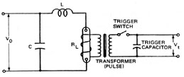
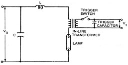
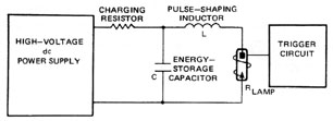
Basic Elements of Pulsed Laser Power Supplies Power supplies of pulsed lasers are designed to store electrical energy in capacitors and to deliver that energy in the form of an excitation pulse to the active laser medium. The current pulse may pass through the active medium as in semiconductor lasers and gas lasers, or it may be used to power a flashlamp for optical pumping of liquid or solid-state lasers. Of the laser types normally operated by electrical pulses, only the semiconductor laser has a relatively constant electrical resistance. This type of laser is powered by an electrical pulse generator that provides short-duration, low-energy pulses. The specifications for such a power supply are included in Module 3-11, "Semiconductor Lasers." Other pulsed laser types use an electrical pulse to power gas-discharge devices such as gas laser tubes and flashlamps. These devices all have the negative dynamic resistance characteristic described for gas discharges in Module 3-1, "Power Sources for CW Lasers." Such power supplies generally consist of the following three elements: · An energy-storage and pulse-forming section, usually an LC network. Energy is stored in the capacitor of the network. When the laser is fired, an RLC circuit is formed in which the resistance is the resistance of the gas discharge. The inductor is chosen for the best energy transfer from the capacitor to the flashlamp or laser tube. · The charging supply is a dc power supply used to charge the energy-storage capacitor to the proper operating voltage. Typical voltages are several kilovolts several configurations of charging supply may be used. Module 3-1, "Power Sources for CW Lasers," describes continuous power sources for CW lasers. The same basic considerations and concepts are used for charging supplies of pulsed lasers. · The triggering circuit delivers a trigger pulse to ionize the gas and begin the discharge. The energy-storage system usually has a maximum voltage below the breakdown voltage of the gas discharge. Thus, a high-voltage pulse is required to initiate ionization. Although pulsed power supplies are employed with several types of gas lasers, the most common pulsed laser power supply type is that used to power the flashlamp of pulsed solid-state lasers. Figure 1 is a simplified diagram of such a supply. A high-voltage dc power supply is used to charge an energy-storage capacitor. The charging resistor protects the supply by limiting current during charging. When the capacitor is fully charged, this supply is usually disconnected from the capacitor, but this is not always the case. A trigger pulse is supplied to the lamp by a high-voltage trigger circuit. This ionizes the lamp and allows the capacitor to discharge through it. The inductor shapes the discharge pulse for the best energy transfer.
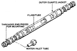
Fig. 1 This module discusses components used in the power supplies for pulsed solid-state lasers and design of the pulse-shaping and triggering sections of such supplies. Flashlamps and their Characteristics Spectral characteristics of flashlamps and the theory of optical pumping are discussed in Module 3-3, "Energy Transfer in Solid-State Lasers." The discussion of flashlamps in this module is concerned with their characteristics that affect the design of the power supplies used in them. Flashlamp Construction Although other lamp types are sometimes used, xenon flashlamps are by far the most common light source for optical pumping of lasers. The lamps are made of fused quartz tubing with a typical wall thickness of 1 mm. Each end of the tube is sealed to an electrode assembly by a quartz-to-metal seal. The lamps are filled with xenon to a pressure of 300-400 torr (mm Hg). Such lamps are available in a wide range of sizes in both linear and helical configurations. Figure 2 shows a typical linear xenon flashlamp. This lamp is intended for air-cooled operation and is fitted with an external trigger wire looped around the lamp. A high-voltage pulse applied to this wire ionizes the gas inside the lamp. Figure 3 shows a linear xenon flashlamp for water-cooled operation. The basic linear lamp has been fitted with a water jacket with O-ring seals at each end. Cooling water flows through the end fittings and around the lamp. This lamp has no trigger wire and is intended for use with a series injection internal trigger circuit that applies a high-voltage pulse to the lamp anode.
Fig. 2
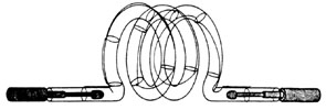
Fig. 3 If external triggering is used, the trigger wire is wrapped around the water jacket. Because this requires higher trigger voltages, water-cooled lamps are generally triggered internally. Linear flashlamps are chosen so that the dimensions of the discharge volume are the same as those of the rod to be pumped. These volumes are optically matched in the design of the laser pumping cavity configuration. Figure 4 shows a helical flashlamp. This type of lamp is formed by winding the quartz tubing into a helix. The laser rod is placed in the center of the helix. Helical lamps provide more uniform pumping of laser rods than do linear lamps, but their overall efficiency is lower because less of their energy can be coupled into the rod by the reflector of the pumping cavity.
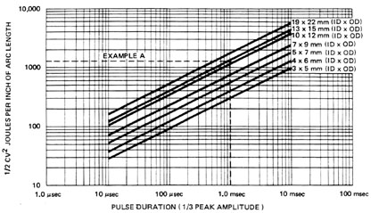
Fig. 4 Lamp resistance depends upon discharge length. Higher lamp resistance results in longer electrical and optical pulses with simple RLC discharge circuits. Thus, helical lamps are popular in systems using longer pulse durations. The lamp shown in Figure 4 has an external trigger wire and is intended for air-cooled operation. The same lamp without the trigger wire may be used with water-cooling and internal triggering in the flooded cavity of a pulsed solid-state laser. Lamp Lifetime The lifetime of a flashlamp is rated according to the number of "shots" or discharges it will undergo before it is no longer operable, or until its output light level drops below an acceptable level. Lifetime varies with pulse duration, peak loading of the lamp, and risetime of the current pulse. Lamp failure is characterized by either a catastrophic explosion or fracturing of the lamp envelope, or by a gradual lowering of the output (that is, due to absorption of light inside the lamp). Lamps usually explode for one of two reasons. The most likely reason is fracture caused by the mechanical shock wave produced by a rapid increase in gas temperature and pressure as the lamp ionizes. Severity of the shock wave is dependent upon risetime of the current pulse. Thus, discharge circuits are designed to avoid extremely short risetimes. Even with optimum pulse shape, there is a definite upper limit to the energy a lamp can withstand for any particular pulse duration. If maximum power of the pulse is excessive, pressure inside the lamp exceeds the tensile limit of the envelope, and the lamp explodes. Figure 5 is a graph of explosion energy per inch of arc length versus pulse duration for linear xenon flashlamps. Lines that indicate explosion energies of seven different lamp diameters are shown. The vertical scale is calibrated in joules of explosion energy per inch of arc length. The horizontal scale is in seconds of pulse duration, with pulse duration defined as the full width of the pulse at one-third the maximum power. Example A illustrates the use of this graph in determining the explosion energy of a lamp.
Fig. 5
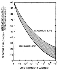
At energies below the explosion energy, lamp failure consists of a gradual reduction of lamp output for one of two reasons. Optical output may decrease due to contamination of the gas inside the lamp. This can occur because of inadequate cleaning of the lamp components before the lamp is filled or electrochemical processes. For example, impurities trapped in the lamp walls or the electrodes can be liberated by heating and ion bombardment during lamp operation. A second source of contamination may be leaks in the seals at the ends of the lamp. Air that enters such a leak will contaminate the gas and raise the pressure. If the lamp reaches atmospheric pressure, it cannot be triggered. Condition of the gas in a flashlamp can be checked by removing the lamp from the laser, connecting one electrode to ground or some large metal mass, and exciting the other electrode with a Tesla coil (a high-voltage, high-frequency but low-current transformer). A good lamp will ionize with one or more thin, blue-white arcs dancing around inside the envelope. If, however, the arcs are very white or clear, or the tube glows violet, or no ionization occurs, the lamp is probably faulty or contaminated. Although not infallible, the Tesla coil test is a very easy, quick indicator of lamp quality. In most cases lamp output decreases gradually over a long period of time due to increased absorption of light within the lamp. If the lamp is operated at high peak power densities, that is, at energies that are a significant fraction of the explosion energy, a small portion of the wall material is vaporized during each shot. When it recondenses, this material is usually in a crystalline state and appears as a white powder on the inner surface of the tube. On successive firings this coating absorbs more light energy and increases both thermal and shock effects on the tube walls. Optical output of the lamp is degraded until it finally fractures. If the lamp is operated at pulse energies well below the explosion energy, the lamp failure mechanism is light absorption due to a dark deposit formed on tube walls. This deposit is the result of sputtering material from the electrodes when the lamp is fired. Sputtering rates depend on the peak power of each laser pulse and the pulse rate for a high-repetition-rate system. Figure 6 is a graph showing the life expectancy of a typical xenon flashlamp as a function of the percentage of explosion energy used with the lamp. This graph is the result of experimental studies in which lamp lifetime was defined as the number of shots at which light output dropped to half the original value.
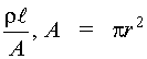
Fig. 6 Lamp Electrical Characteristics Electrical resistance of a flashlamp during discharge can be calculated by use of the conventional formula for resistance:
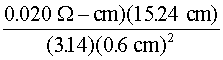
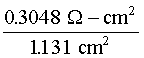
Example B illustrates the use of Equation 1 in determining the resistance of an Xe flashlamp.
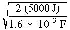
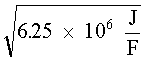
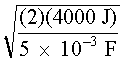
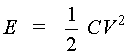
Resistivity of the xenon gas is not a fixed value, but depends upon the degree of ionization of the gas and thus on the current density. The current density is defined as current per cross-sectional area of the lamp and is measured in amperes per square centimeter (A/cm2). An increase in current density decreases the resistivity of the gas. Typical values for the resistivity of xenon in laser flashlamps are from 0.015 to 0.025 ohm-cm. Under normal operating conditions, shorter-duration pulses tend to have higher peak current densities. A general rule of thumb is to use r = 0.015 W –cm for pulse duration of less than 100 m sec, r = 0.20 W –cm for pulses between 100 m sec and 1.0 msec, and r = 0.025 W -cm for pulses longer than 1.0 msec. Because current density in the lamp varies during the electrical pulse, resistivity and total lamp resistance also vary. Effects of these variations on pulse shape and circuit design are discussed later in this module. Energy-Storage and Pulse-Shaping Circuits High peak power outputs from flashlamps are achieved by slowly storing electrical energy in high-voltage capacitors and discharging them very rapidly (in a few milliseconds or less) into the flashlamp. The amount of stored energy in the capacitor bank is determined by the value of capacitance (in farads) and the voltage to which the bank is charged. Stored energy in a capacitor bank can be calculated with Equation 2.
Example C illustrates the use of Equation 2 in determining energy stored in a capacitor.
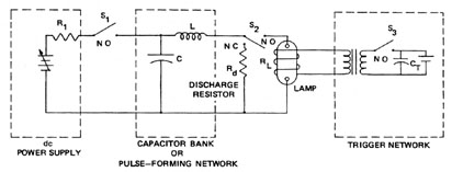
Two types of capacitor discharge circuits are used for laser flashlamps. They are the RLC discharge circuit and pulse-forming network (PFN). The choice of circuit to be used for a particular application depends upon required pulse length, pulse shape, energy to be discharged, and desired charging voltage. Generally speaking, RLC circuits are used to generate short pulse lengths and PFNs are used for longer pulse-length requirements or a constant power level during their discharge. Minimum capacitor charging voltage is determined largely by the arc length of the lamp, as it is not easy to ionize a lamp and sustain a discharge current if the voltage on the capacitor is too low. Exact minimum values are somewhat variable, but a good rule of thumb is that 600 V is required for a 3-inch arc length, and 1.0 kV for 6 inches, and ~1.5 kV for 12 inches. RLC Discharge Circuit The pulse-shaping circuit shown in Figure 1 is an RLC discharge circuit. It consists of a single capacitor for energy storage, a single inductor for pulse shaping, and a resistive load in the form of the flashlamp. Energy initially is stored in the capacitor. Because the flashlamp initially has infinite resistance, the RLC series circuit is open. When the flashlamp is triggered, the circuit is complete and current begins to flow. Current (I) will circulate in the loop until all energy stored in the capacitor is dissipated in the resistor R (I 2R type heat). Current will not remain constant but will vary during the discharge. The way it varies depends principally upon the values of the circuit components. Current discharge, as a function of time, can be described by Equation 3.
The discharge current can follow three general behavior patterns, depending on the value of the circuit elements. These are shown in Figure 7. First it must be determined whether the current will "ring," or oscillate (as shown in Figure 7a).
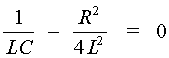
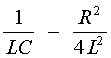
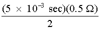
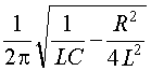
Fig. 7 The term If the expression The desired condition for fast pulse discharge is very nearly the critically damped case, as shown in Figure 7c. The design equation for this condition is:
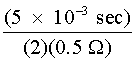
Equation 4 may be used to determine the inductance necessary for critical damping as is illustrated in Example D. Pulse duration of the current pulse is approximately equal to the RC time constant of the circuit given by Equation 5.
Equation 5 may be used to determine the capacitance necessary to produce a given pulse duration if the lamp resistance is known, further illustrated in Example D.
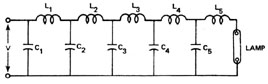
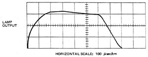
RLC Circuit Design Procedures Several design procedures may be followed for the design of RLC circuits. The procedure generally begins with selection of lamp dimensions, pulse duration, and minimum number of shots acceptable from the system although, in some cases, input energy per pulse is taken as a starting point rather than pulse duration. The following is a typical procedure for designing the RLC circuit for a pulsed solid-state laser: 1. Select lamp dimensions based on rod dimensions. 2. Determine desired pulse duration of system (arbitrary decision based on system application, or properties of active laser medium). 3. Determine minimum number of shots acceptable for the flashlamp (arbitrary decision). 4. Determine lamp resistance from Equation 1, using the appropriate value of resistivity based on pulse duration. 5. Determine the necessary capacitance from Equation 5 as illustrated in Example D. 6. Determine the necessary inductance from Equation 4. 7. Determine the percentage explosion energy to be used to obtain the required lamp lifetime using Figure 6. 8. Determine explosion energy of the lamp using Figure 5 as illustrated in Example A. 9. Determine the lamp input energy by multiplying the explosion energy times the fraction of explosion energy to be used. 10. Determine the capacitor voltage using Equation 2 as illustrated in Example D. The above procedure is an approximate design procedure and is based on the assumption that resistivity of the lamp is a known constant value. Because this is not the actual case, circuits designed by this procedure often vary considerably in their actual performance from theoretical values. The current pulse through such a circuit should be monitored to determine if the system is over, under, or critically damped. This may be accomplished by measuring the voltage across a current-viewing resistor placed in series with the grounded lead of the flashlamp. This resistor may be constructed of a straight piece of heavy copper wire. It should have a resistance of only a few milliohms to avoid loading the circuit. If the system is found to be underdamped, inductance should be increased to prevent ringing. If the system is critically damped or slightly overdamped, no changes are necessary. Many commercial laser systems use RLC circuits that are purposely overdamped. Because changing energy per pulse changes current density and lamp resistance, a circuit that is critically damped for one capacitor voltage may be underdamped at another. Circuits with slight overdamping avoid ringing at all charge voltages. More sophisticated design procedures may be used to produce a critically damped circuit for a given lamp, initial voltage, and pulse duration, but it is still necessary to monitor the current and make necessary changes to ensure proper operation of the circuit. PFN Circuits A pulse-forming network (PFN) is composed of a series of LC sections as shown in Figure 8. Pulse-forming networks are used when a given pulse is desired such as a square pulse with a constant current level or when the desired pulse duration is longer than can be achieved with a simple RLC discharge circuit. Figure 9 shows the shape of the output pulse from a PFN with 10 identical LC sections.
Fig. 8
Fig. 9
The design equations for a pulse-forming network of five or more L-sections are given below:
Total electrical energy stored in the pulse-forming network (which is available to be discharged into the flashlamp) is determined by the charge voltage on the capacitors, and can be calculated using Equation 2. Example E illustrates a typical design for a PFN.
Discharge Circuit Components Energy-storage capacitors used in the main discharge capacitor bank are sold by several manufacturers under names such as "photoflash capacitors," "energy-storage capacitors," or "energy-discharge capacitors." These capacitors are specified according to the following criteria:
The energy that can be stored in a capacitor is determined by its capacitance and its charge voltage (see Equation 2). Inductance associated with the discharge circuits will determine the maximum rate of current rise in the discharge for a given load resistance. Average lifetime of an energy-storage capacitor is determined by the quality of dielectric used, charge voltage, length of time the charge voltage is left on the capacitor prior to discharge, and amount of current reversal occurring in each discharge. Typical values of lifetime run from 104 to 106 shots and in special cases approach 108 to 109 shots. Inductors The inductor for a high-current, pulse discharge circuit must be constructed to have low resistance and high mechanical strength. As a good "rule of thumb," total resistance of the wire in an inductor should be less than one-tenth the resistance of the flashlamp. If the inductor is in the shape of an air-core helical coil, a strong magnetic force exists between the adjacent turns during high-current discharge. The force perpendicular to the axis will be in the outward direction—trying to stretch the coil to a large diameter. The force parallel to the axis will tend to collapse the coil, forcing the windings together. To prevent these forces from damaging the inductor, the wire should be wound on the coil spool in grooves, or held in place with potting compound. An air-core inductor can be built in the lab by winding large-diameter wire (#10 or #12) on a cylindrical spool of wood or plastic. Inductance is determined by length of the coil, radius of the coil, and number of turns, according to the following empirical equation:
|
||||||||||||||||||||||||||||||||||||||||||||||||||||||||||||||||||||||||||||||||||


 =
= 

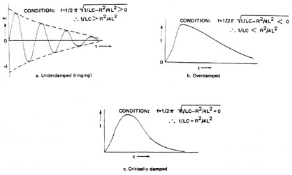
 determines whether the current behaves like Figure 7a, 7b, or 7c. If circuit component
values are such that the expression is positive, then a ringing frequency can be
calculated and the current behaves like that shown in Figure 7a. This is an undesirable
condition for operating a flashlamp because the lamp will "turn off" each time
the current passes through zero and voltage reversals occur on the capacitor.
A voltage reversal is when the voltage reverses across the capacitor during the
discharge. If the resulting current reversal is greater than 20% of the peak current, it
may cause severe stress on the capacitor dielectric and substantially reduce its life.
determines whether the current behaves like Figure 7a, 7b, or 7c. If circuit component
values are such that the expression is positive, then a ringing frequency can be
calculated and the current behaves like that shown in Figure 7a. This is an undesirable
condition for operating a flashlamp because the lamp will "turn off" each time
the current passes through zero and voltage reversals occur on the capacitor.
A voltage reversal is when the voltage reverses across the capacitor during the
discharge. If the resulting current reversal is greater than 20% of the peak current, it
may cause severe stress on the capacitor dielectric and substantially reduce its life.