| This version reflects the comments of the core participants as reviewed and incorporated in accordance with CORD's FIPSE-supported Curriculum Morphing Project. | |||||||||||||||||||||||||||||||||||||||||||||||||||||||||||||
MODULE 5 Changes in red were made as a group by Pete Latham –course director, Yoriko Morita, Nick Massa and Tung Jeong. (1)In our society today we have developed an ever-increasing need to store, reproduce, transmit and process large amounts of information rapidly. We have also seen a swift growth of the technology to deal with data and information, and the field still is evolving. (2)Laser technology has some important applications in the field of recording, processing and transmitting of information. It offers the possibility of revolutionary changes in the way we deal with information, as compared to conventional electronic methods. A good example is optical-fiber telecommunication which has completely changed the telephone industry within the last ten years. (3)Some other potential applications of lasers (computer memories and optical computers, for example) are in earlier stages of development. They offer the potential for exciting advances in the handling and processing of information. This chapter will concentrate on three of these quickly evolving technologies:
(4)The description of data transmission (optical-fiber telecommunication) will be given in a later chapter. (5)Before studying this chapter, you should have a basic knowledge of laser safety including eye hazards and electrical safety. You should know how to operate a helium-neon laser, a helium-cadmium laser, an argon laser, a photodiode and an oscilloscope, and how to adjust a beam-expanding telescope. For a better understanding of this chapter, we suggest that you have a knowledge of laser and electro-optic components, welding, and dynamic cutting and drilling. This chapter does not draw heavily on mathematical development. 
(6)Upon completion of this chapter, you should be able to do the following: 1. Describe:
2. Define:
3. State the most important advantage associated with electrophotography. 4. List the six elements required in an optical data-storage system. 5. Perform calculations related to:
6. Perform experiments related to:
DISCUSSION (7)Laser technology offers many exciting applications in the storage and processing of data. Since there is an ever-increasing need for the rapid processing of larger and larger amounts of data, this represents an extremely important application of laser technology which is growing and changing quickly. (8)This chapter first will describe components that are commonly used with laser-based information-handling systems. This includes a discussion of the lasers that commonly are used for this application and also of the scanners that deflect the beam to prescribed locations in the information field. (9)We then will describe three of the important ways that lasers are used in information-related applications:
Components for Laser-based (10)The components that most often are used in the information-related applications of lasers are the laser and the scanners that move the beam to a specified area in the information field.
Lasers (11)The laser type that is most commonly used in information-related laser-based systems is the semiconductor laser diode. Major advances in recent years have provided stable diffraction-limited operation of long-lived semiconductor lasers that satisfy many of the needs in data-related applications. (12)When information-related applications first were being developed in the 1960s, semiconductor lasers suffered several drawbacks. They tended to be unstable and short-lived. Their large beam-divergence angle made it difficult to collect and focus the light. So, gas lasers, with their well-collimated beams, were used most often in the early investigations. (13)In addition, recording media that were available at that time were relatively insensitive in the red and near-infrared portions of the spectrum. This tended to favor use of lasers operating in the blue and green. Argon lasers and helium-cadmium lasers were used frequently. When the recording medium did not prohibit operation in the red portion of the spectrum, the stable, well-developed helium-neon laser was used often. Early research in this area was dominated by use of these gas lasers. (14)Advances in semiconductor lasers and in the recording media have changed this situation. Recording media with improved sensitivity in the red and near-infrared have been developed. Therefore, there no longer is a need to avoid the spectral region around 800 nm. At the same time, semiconductor AlGaAs lasers with high radiance, excellent stability and long life have become available. (15)As compared to gas lasers, semiconductor lasers offer a number of advantages:
(16)One disadvantage of semiconductor lasers does remain—the relatively large broad-beam-divergence angle as compared to gas lasers. This places demanding design requirements on the optics to provide beam shaping. Optical designers have mastered this requirement. They can provide optical systems that capture the divergent beam and shape it into a circular and collimated beam. So, semiconductor AlGaAs lasers, operating at wavelengths near 800 nm, now are the most commonly used laser type for applications like data recording.
Scanners (17)Many applications of lasers in information-related systems require some method of scanning (i.e. deflecting the beam) to cover an area. The scanner is a device that deflects a beam of light to cover an information field (like a page of printed text) in a regular pattern. For example, in a reprographic system, the entire scene to be reproduced must have the beam pass over it. So, scanning technology is a important part of the subject of information-related applications. (18)Two main methods have been employed for laser beam scanning:
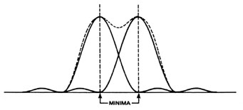
(19)Acousto-optic methods for light-beam deflection are described in other chapters. In this chapter: we will describe light-beam deflection that involves mechanical methods; that is, devices that employ moving parts. (20)First, let us consider the definition of resolution in a scanning system. Light-beam deflection is measured in terms of "resolvable spots," rather than in terms of absolute angle of deflection. One resolvable spot means deflecting the beam by an amount equal to its own angular spread. One resolvable spot is one separate distinguishable angular position that the beam can take and that can be distinguished from a neighboring position. (21)The standard criterion for resolution is the so-called Rayleigh criterion. According to this criterion, two intensity distributions* are just barely resolved when the maximum of one distribution overlaps the first minimum in the diffraction pattern of the second distribution. Figure 1 indicates two spots that are barely resolved according to the Rayleigh criterion. The solid lines represent the diffraction patterns of the individual distributions. The dotted line represents the sum of the two light distributions.
Fig. 1
(22)The number of resolvable spots is one of the most important parameters that characterize a light-beam deflector. The number of resolvable spots is essentially the total angle through which the beam can be deflected by the deflection device, divided by the angular spread of the beam. This gives the number of separate distinguishable spots to which the deflector can send the light beam. (23)The most simple and obvious method of deflecting a light beam from one position to another is to allow the beam to strike a mirror, and then to rotate the mirror slightly. This concept forms the basis for the mechanical light-beam deflector. All mechanical deflectors involve mechanical motion of some component. Typical mechanical deflectors consist of a mirror or prism that is moved in some manner so as to send the beam from one position to a different position. Three main methods are used in such scanning systems: rotating mirrors, galvanometers, and holographic deflectors. (24)The basic concept of the mechanical deflector is straightforward. However, there are several practical limitations. Because mechanical motion is involved, the speed of mechanical deflectors does not compete with non-mechanical deflectors, such as accousto-optic deflectors. (25)Generally speaking, mechanical light-beam deflectors produce large deflection angles with relatively low speeds, whereas nonmechanical deflectors tend to produce smaller angles of deflection at high speeds. It’s very difficult to achieve a large angle of deflection with high speed and high light intensity. (26)In the next section we will describe the types of mechanical light-beam deflectors.
Rotating Mirrors (27)Rotating mirror deflectors often consist of a polygon-shaped mirror mounted on a fast-rotating shaft. The sides of the polygon are polished to a mirror finish. The laser light strikes a side of the polygon and is scanned in a line as the mirror rotates. When a new side of the polygon rotates into the beam, the line is rescanned, starting at the beginning. Figure 2 shows the structure of a rotating polygon mirror. (28)If the polygon has n sides, incident laser light reflected off each side is deflected through an angle of +360° /n from the normal. If the motor speed is w revolutions per second, the deflection rate is nw lines per second. Mechanical deflectors of this type have used motors with speeds as high as 2000 revolutions per second. With a three-sided mirror, a scan rate of 360 million spots per second has been demonstrated. However, the access time for such a deflector is long because of the sequential nature of the scan. One must scan through the entire line starting at the beginning. If a particular point is desired, it is necessary to go through the entire sequence of points along the line until the desired point is reached. (29)Synchronization with other time-dependent elements in the system is rather difficult. Motor stability and durability at higher rotation speeds also present problems. There is an upper limit to the rotation speed. This limit is due to the tensile strength of the mirror material. The mirror must not disintegrate at the maximum rotation speed. Often, polished beryllium mirrors are used because of their high strength-to-weight ratio.
Fig. 2
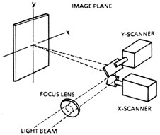
Galvanometer Mirrors (30)This approach uses a small mirror mounted on the current-carrying coil between the poles of a permanent magnet. When an electrical current pulse is applied to the coil, it rotates in the field of the magnet. This is the same type of operation that galvanometers employ. The mirror can be rotated to any position within its range simply by pulsing the electric current. Figure 3 shows a typical arrangement for using two galvanometers to scan a two-dimensional image plane.
Fig. 3
(31)There are two distinct classes of galvanometer that exhibit different ranges of performance.
(32)A broadband galvanometer can execute a linear ramp or hold a fixed position. It can thus be useful as a scanner in a random-access memory because it can address any arbitrarily chosen position. Broadband galvanometers are useful for operation at frequencies up to 300 Hz. They can cover up to 2000 resolution elements per scan. (33)Broadband galvanometer deflectors offer several advantages. As compared to the rotating mirror, they do not have a sequential scan. One can go directly to any desired angular position simply by applying the correct current pulse. They can achieve large deflection angles (tens of degrees) and large numbers (thousands) of resolvable spots. (34)The resonant galvanometer follows a sinusoidal (sine-wave) scanning function at a fixed resonant frequency. It is useful for scanning a repetitive pattern. It is capable of operating at higher frequency than the broadband galvanometer—in excess of 4000 Hz. It can cover more than 10000 resolution elements per scan. (35)In practice, one might choose a broadband galvanometer for use in a newly developing experimental application because of its greater adaptability to varying situations. For an established operation, where the operating parameters are fixed and repetitive high-speed operation in unchanging condition is desired, the resonant galvanometer has a superior performance. (36)Galvanometer deflectors probably represent the leading type of mechanical deflector in use. Present galvanometers are well-designed and offer good performance over a wide range of operating parameters. (37)One can choose a galvanometer from many commercial models. The choice involves a trade-off between speed and the number of resolvable spots. To have a large number of resolvable spots, one must make the mirror large so as to reduce the angular spread of the beam set by diffraction at the mirror. However, a large mirror is heavier and slower to drive than a smaller mirror. (38)Table 1 summarizes characteristics of some commercially available galvanometer devices. The access time is the time required to move the mirror so that the beam is deflected to an arbitrarily chosen position. The access time will increase as the size of the angular motion increases. The number of resolvable spots is calculated as the magnitude of the peak excursion divided by the angular spread of the diffraction-limited beam for 0.6-m m wavelength radiation reflected from the mirror with the given dimension. Nonrepeatability and jitter of the mirror motion may reduce this number somewhat. From the table, we see that the speed of access to a given position decreases as the number of resolvable spots increases. The table shows that galvanometer deflectors are available with a wide range of properties. Such deflectors are widely used for many practical applications. Table 1. Galvanometer Properties Broadband Galvanometers
Resonant Galvanometers
Based on information from General Scanning, Inc.
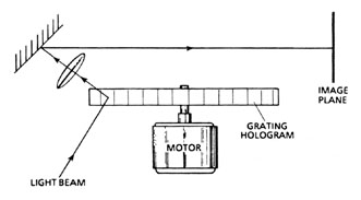
Holographic Scanners (39)Holographic scanners are essentially holographic images of rotating polygons. They can thus be regarded as a variation of the polygon mirror. They are similar in performance to the rotating polygons. (40)Holographic scanners are produced by photographic techniques. So, they are easier to fabricate and are less expensive than polygon mirrors. They do require high-quality optics and considerable care in their preparation. (41)In one common form, the holographic scanner takes the form of a disk which is rotated about its axis, as shown in Figure 4. The figure shows a transmission hologram encoded on the rotating disk. The holographic gratings encoded on different sectors of the disk represent the different facets of the rotating polygon. The incident light beam is diffracted by the hologram to form an aberration-free point image of the source used to fabricate the hologram. As the hologram rotates, the point image is scanned in a circle in the image plane.
Fig. 4
(42)One example of a high-performance holographic scanner has demonstrated a combination of very high resolution and scan rate—20000 resolution elements per scan at a scan rate of 2 ´ 108 elements per second. (43)Holographic scanners are less mature than other types of mechanical scanners, but they are developing rapidly and are replacing rotating polygons for some applications. (44)In summary, the main advantage of mechanical deflectors lies in the fact that there is no volume interaction of light with the medium. The deflector has only a single surface, a mirror. Distortion of the beam because of imperfect medium quality is avoided. Other advantages of mechanical deflectors include a large number of resolvable spots or large deflection angle, small loss of light in the deflected light beam, and relatively low driving power. In addition, the cost of mechanical deflectors is generally much lower than the nonmechanical deflectors. (45)In general, however, the accuracy of the deflection and the scanning speed are both lower than for nonmechanical deflectors. This is because mechanical deflectors always involve physical motion of some piece of material, and the inertia of the mass of material limits the speed at which the light beam can be deflected. The mass can be reduced and the speed increased by using smaller and smaller pieces of material, but there is a limit to the minimum size that can be used. To achieve higher speeds, one must use inertialess light-beam deflectors for which there is no obvious physical motion of any material.
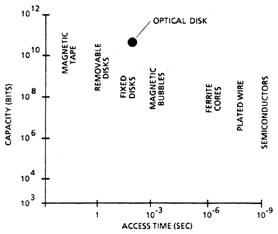
Optical Data Storage (46)Lasers and electro-optic technology have many applications in the field of data storage. The amount of data and information processed by computers is increasing at a tremendous rate. New and more sophisticated methods of storing and processing this vast amount of information are required by the computer industry. Laser and electro-optical techniques offer possibilities for significant improvements. (47)The field of optical data storage is in a period of rapid growth and development. It is not possible to predict the exact course of product development. Therefore, in this chapter we will survey some of the promising areas and discuss some of the techniques and materials that are used now and that appear most likely to be used in the future. (48)Figure 5 shows the capabilities of some of the different technologies that are used for computer memory. The figure represents a plot of capacity (total bits stored) versus access time. We see that there is a trade-off between speed and total capacity of the memory.
Fig. 5
(49)Computer manufacturers want to store more and more information and to access it faster. That is, they want to develop products that move toward the upper right corner of the figure. The point denoted "optical disk" represents the capabilities of compact optical disks, as of 1987. Optical data-storage technology thus represents an advance in the state of computer memories. (50)The effects produced by laser radiation can be used for recording of information. It is obvious that heating, melting, and vaporization produced by a laser beam can be used for information-storage purposes. In a very simple system, for example, a laser beam could be focused to a small spot on an opaque film and a small hole burned in the film. The information represented by the hole in an otherwise opaque film can be read optically. A single hole can represent one bit of information. That is, the presence of a hole in a given position can represent a one and the absence of a hole can represent a zero.* (51)Optical information-storage technology has been under development for a number of years. In the early 1960s, the capability of lasers for recording and retrieving information in the form of bits was recognized. Early workers with the first lasers noted that lasers could make marks on recording materials. The marks would represent bits of information. The presence of a mark could be detected by reflection of the laser beam. However, despite many years of intensive effort in the field, commercial data-storage systems did not emerge until the 1980s. (52)At the present time, new types of optical data-storage systems are being introduced and the field of optical data storage is in a process of rapid growth and change. Optical data storage represents a potential for revolutionary changes in the technology of information storage and retrieval. (53)Perhaps the most important advantage that laser-based optical storage systems offer is high packing density. The laser beam can be focused to focal spots having diameters of approximately one wavelength, less than 1 micrometer for common lasers. This means that data points can be stored with a center-to-center separation around 1 micrometer, leading to packing densities of 108 bits per square centimeter or greater. This is an important consideration as the needs for storage of large amounts of data within a small space are continually increasing. (54)The basic principle of laser-based optical data storage is shown in Figure 6. A laser beam is focused on a recording medium in which the information is stored in some fashion. In many common systems in use today, the information is stored in the form of pits, which represent bits of information. The reflectance of the medium is different, depending on whether a pit is present or not. The beam reflected from the surface is sent through a beam splitter to a detection system that senses the level of the reflected light and detects whether a pit was present in a given area and so, whether the area corresponds to a 0 bit of information or to a 1 bit.
Fig. 6
(55)Optical data storage requires several technologies:
(56)In the next paragraphs, we will describe the components and devices that are used to meet these needs. (57)The light source is provided by a laser. In early optical data-storage systems, helium-neon lasers were encountered most often. Early semiconductor lasers were not adequate for this application. In more recent times, semiconductor diode lasers operating at a wavelength around 800 nm have become widely used. Recent advances in the technology of laser diodes have made them satisfactory sources for optical data storage. Because of their small size, light weight, and low cost, semiconductor diode lasers are now the preferred laser for this application. They have largely displaced the hellium-neon lasers. (58)The focusing optics basically consist of a lens with an auto-focus system. The beam must be kept sharply focused on the surface to detect the stored bits. A number of different ways to check and correct the focus have been developed. (59)One method for adjusting focus errors uses a laser beam that strikes the surface of the storage medium at non-normal incidence. This leads to an offset of the distribution of the light reaching the detector, which is split into several segments. Changes in the balance of the light pattern on the different segments can be interpreted in terms of the change in the focus, and can be used to adjust errors in the focus. (60)Typically, the data are stored in the form of tracks of bits on a rotating disc. Some means is required to ensure that the beam remains focused on the track. A number of different methods are employed for tracking. In one example—called the radial push-pull method—the detector is split into two halves. If the beam is off the track slightly, there will be a difference in the signal level in the two halves of the detector. Asymmetry of the reflected beam due to departure from the center of the track is determined by the relative signals in the two detectors. This is used as a feedback to the positioning system to keep the beam on the center of the track. (61)The data-storage medium is crucial to the operation of the system. Recording media can be considered as:
(62)The prerecorded media have the information recorded in the form of pits in the recording surface. Many of today’s systems use a tellurium-based alloy to record the information. The tellurium alloy is melted to form a pit in the locations where it is desired to store a bit of information. The tellurium alloy melts at a low temperature. So the recording can be done with an optical beam focused through the same optics as are used for the readout. (63)A schematic diagram of a pattern of roughly circular pits spaced along tracks about 1 m m apart on a 51/4-inch-diameter rotating disk is shown in Figure 7. The difference isn reflectivity between the case of a pit and no pit gives the readout. In this format, the data is prerecorded and is not changeable by the reader.
Fig. 7
(64)The actual fabrication of prerecorded disks in large numbers may involve a series of steps:
(65)Recordable media also use a tellurium-based alloy incorporated in a system in which the laser power can be increased to provide the melting and to record bits. For readout, the laser is operated at lower power so that no further melting will occur. With these systems, the user can write once and record the data that he wants to use. Since the recording is in the form of an irreversible melting of the material, the disk, once recorded, cannot be erased. A number of commercial models of such systems were introduced in the mid 1980s. They are sometimes called WORMS, which stands for "write once read mainly." (66)Different types of erasable recording media are under development. One example is thermomagnetic materials, in which the information is stored as a change in the direction of magnetism of a magnetic material. The readout is through magneto-optic effects. (67)The detection system for an optical storage system usually involves the use of photodetector, often a silicon photodiode that uses the reflected return from the storage medium. The detection system is capable of determining the difference in reflection from a 0 and a 1 bit. It is also called on to perform tracking and focusing functions. Therefore, it may take the form of a split photocell. (68)Finally, data encoding and decoding software and error detection and correction algorithms are necessary. For current systems with error detection and error correction, rates as low as one mistake in 1012 bits are possible. The error correction involves checking codes that verify the data. Some "smart" checking codes also can look for certain errors and correct them. A diagram of the entire system is shown in Figure 8.
Fig. 8
(69)The disk fits on the spindle/motor servo assembly which rotates at exactly 1800 rpm. The laser produces a beam of light which passes through a focusing/positioning chapter and strikes the surface of the disk. The beam reflects back into the chapter and strikes a beam splitter which reflects it to a segmented photodiode. The diode produces signals that allow the drive system’s electronics to detect the presence of data pits on the surface of the disk as well as the information necessary to focus and track the concentric rings of data on the disk. (70)Several kinds of storage products are available. Video disks are suitable for storage of information in video format, that is, images that are displayed on a TV monitor. They have been in use in commercial products since the late 1970s. They are used most often for applications such as entertainment (playing movies) and for video-based educational programs. (71)Compact disks (CDs) are suitable for presentation of data stored in bit form. They form the basis of a highly successful audio reproduction system introduced in the early 1980s. This has been an extremely popular consumer product. They also are used in the so-called CD ROM format (compact disk read only memory) for storage of binary data. A large number of training, educational and reference products based on CD ROMs are becoming available. (72)The user-recordable compact disk, the "write-once" compact disk, flourished in the mid 1980s. Commercial units capable of storing 400 megabytes are now available, with access times around 20 ms. This capability is approaching the point represented in Figure 5. (73)Optical data storage offers a number of advantages:
(74)As an impressive example of the capability of the high packing density, we note that the contents of 50,000 sheets of printed information could be stored on a single 51/4" compact disk. (75)Optical data storage is growing rapidly and spreading into many new applications. It offers many exciting new possibilities that have yet to be examined fully. Potentially, it offers revolutionary changes in the entire field of data storage.
Reprographics (76)Reprographics refers to the reproduction of information. Laser-based reprographics is in a state of explosive growth, with many new commercial products introduced in the 1980s. These products have had excellent consumer acceptance. The two most notable products have been associated with non-impact printing. These two products are laser-based photocopy machines and laser-based printers for computers. (77)The process of non-impact printing for computer output involves conversion of electrical signals stored in the computer to a printed form on a sheet of paper. The electrical signals are used to modulate a laser (i.e. turn it on and off), to record the signals on a photosensitive medium. To print on plain paper, one must go through an intermediate step of recording on a rotating drum coated with a photosensitive material and then transferring the image to the paper. This process involves electrophotography. (78)Electrophotography is also the process used in photocopy machines. But the input for the photocopy machine is an original document, rather than electrical signals from a computer. In conventional copiers, the light from a source illuminates the surface of the document to be copied and the document is imaged onto the surface of the plate. In a laser printer or copier, light from a modulated and raster-scanned laser forms the image. This difference allows much higher versatility for laser-based devices. No original document is necessary to make a copy. The image can be generated in the form of text or of drawings directly from a computer’s memory. (79)Because of its importance in these two laser-based consumer products, we will describe electrophotography in detail. (80)Electrophotography—also called Xerography—is the reproduction process used in laser-based printers and copiers. The process uses a cylindrical surface, called a drum, that rotates during the printing process. The surface of the drum consists of a thin photoconductive coating whose resistance is sensitive to light, allowing the image to be stored as a variation in the cylinder’s surface charge. In an actual printer different steps take place at different locations around the circumference of the drum so that the production of the image on paper is a continuous process. For simplicity, this discussion will assume that the sensitive surface is a flat plate and that the process takes place in six discrete steps.
Fig. 9
(81)The first step removes electrons from the photoconductor, leaving the surface with a uniform positive charge. This occurs in a dark environment where the photoconductor has a high resistance which prevents the charge from being neutralized by the electrons in the drum. (82)During the second step an image is projected onto the photoconductive surface. It may be created by a conventional lens system or by a modulated laser beam which is raster-scanned across the surface. The light lowers the resistance of the surface layer and allows the illuminated areas to discharge. The dark areas on the plate have a high resistance and retain their charge. These variations in resistance across the surface of the plate create a charge pattern which represents the optical image. (83)In the third step, the plate passes near a reservoir containing a colored toner. The charged areas on the plate attract the dust-like toner particles and form an image on the plate. (84)The fourth step transfers the tone image to a sheet of paper. A positive charge on the sheet attracts the tone particles to the paper, thus transferring the image from the drum to the paper. (85)The fifth step heats the paper, which fuses the toner particles together and bonds them to the surface of the paper, creating the hard-copy output from the printer. (86)The last step cleans the remaining toner from the surface of the plate so that the process can begin again with a blank plate. (87)Laser reprographics is also used for recording computer output, on either microfilm or on-line printers. In such systems, the signal for the modulator is generated directly by the computer. Information can be recorded as binary bit patterns or as alphanumeric characters. Laser printers and copiers represent rapidly growing product lines, which are supplanting conventional reprographic equipment. (88)In addition to these two familiar consumer products, there are many other important applications of lasers in reprographics, such as facsimile systems for long-distance transmission of documents and images, and laser-based phototypesetting machines used by newspapers. (89)Facsimile systems involve scanning a laser beam across a picture or textual material that is to be reproduced. A low-power laser beam is scanned in a raster pattern across the surface of the document. Light reflected from the surface scanned by the laser is detected by a photodetector. The output of the photodetector is used as the input signal for a modulator. The modulator controls the intensity of a second laser beam that is used for recording or reproducing the image. When the scanning laser sweeps over a bright area in the document, the reflected intensity and the detector response will be high. (90)The lasers used in photocopy machines and in laser printers are most often semiconductor lasers (AlGaAs) operating at a wavelength around 0.8 m m. Some early models used HeNe lasers, and some expensive top-of-the-line machines use HeCd or Ar lasers. The electrical signal from the detector, when input to the modulator, will allow a high value of light intensity to reach the recording medium. The bright area will be reproduced. Converse statements apply to dark areas in the original scene. (91)Facsimile systems can be used to reproduce documents at remote locations. The scanning laser with its deflection system is at one location. The recording laser, its deflectors and modulator and the recording medium, are at another location. The signal to control the modulator is transmitted between the two locations. (92)Laser reprographics is finding application as the basis for wirephoto systems used for newspaper photos. It has also been incorporated into telecopier systems for business use. The photograph or document is scanned at one location and reproduced at a second, remote location. (93)Laser reprographics also involves laser phototypesetting systems. Phototypesetting involves photographing characters on film. Phototypesetting machines select a negative of a desired character, under the control of a keyboard. The image of the character is projected on the photographic film. When the film is developed, it serves as the basis for making the printing surface. The substitution of a laser as the light source in a phototypesetting operation offers cost reductions. Sophisticated laser typesetting machines are being used in the newspaper industry.
Optical Data Processing (94)Optical techniques can be used for processing of data in the central processor of a computer. There are two approaches to optically based computer technology:
(95)Digital optical computing probably will use optically bistable elements as switches, but it’s in a research stage. Despite a large amount of research in this area, there are no real operating digital optical computers. It probably will be many years before optical digital computer products reach the market. Therefore, we will consider only the analog approach to optical data processing in this chapter. (96)Analog optical data processing has been used for a number of different operations. It is suitable for specific applications in which the data to be processed is already in an optical format, for example a photograph. Optical data processing has been used for applications such as:
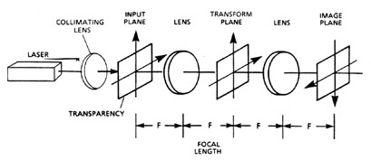
(97)The most common type of operation involved in optical data processing involves filtering the spatial components of a two-dimensional picture. This procedure is called Fourier transform filtering because it involves taking the Fourier transform of the photograph. This transformation converts the spatial intensities in the photograph into a two-dimensional frequency representation. This conversion is the two-dimensional analog of the Fourier series which converts a complex temporal function into a sum of a sequence of sine and cosine functions. The transform may be mathematically calculated by digitizing the photograph and then using a computer to calculate the transform as a set of numbers or by using an optical system to produce the transform at a particular plane in space. The transformed image can then be manipulated to remove, add or enhance certain frequencies in the image. Finally, it is retransformed to create a modified image of the original picture. (98)The transformation allows an operator to remove scan lines from TV pictures, enhance fine detail in reconnaissance photographs or even to identify a single name in a newspaper page. The range of applications is limited only by the imagination of the operator, the resolving power of the film and the noise characteristics of the system. This section will limit its discussion to optical transformation systems. (99)The apparatus used for optical transforms is shown schematically in Figure 10.
Fig. 10
(100)A collimated, monochromatic source of light is required. In practice, the source is almost always a laser. It is possible to use another source but the high brightness and monochromaticity of a laser make it the most practical source. In either case the resulting beam is collimated by the first lens so that a plane parallel beam of light strikes the transparency to be processed. The distance from the collimating lens is not important but the transparency must be located exactly one focal length from the first transform lens. The light that passes through the transparency is focused by the first transform lens, one focal length beyond the lens. Geometric optics would predict that all of the light would be focused to a point on the optical axis, however wave optics and diffraction also act on the light. The result is neither a point nor an image of the transparency, it is the Fourier transform of the original image with the light displayed in a complicated two-dimensional pattern. (101)A complete description of the tranform pattern is beyond the scope of this text but some of the features will be described. Slowly varying regions of the transparency are represented by light that appears near the optical axis, while rapidly varying regions are represented farther from the axis. The more rapid the variation the farther it is from the optical axis. Horizontal features in the original transparencies transform to vertical spots and vertical features transform into horizontal spots much as a multiple slit spreads the light in a direction perpendicular to the slits. (102)The light continues along the optical axis and strikes a second lens which performs the inverse transform and creates an image of the original transparency. If the lens system has no aberrations, and if the laser beam is perfectly collimated and all the light from the transform plane reaches the second transform lens, then the image will be an exact copy of the original transparency. However, the goal of a system is not to generate an exact copy of the original, it is to change the characteristics of the original scene. This is accomplished by changing the pattern of the light that is focused at the transform plane. (103)Let us consider several examples where transforms may be useful. The first will be television images returned to earth from NASA spacecraft. They consist of the television scan lines superimposed on the image of a planet’s surface. The scan lines detract from the image and need to be removed. Fortunately they represent a high-frequency horizontal pattern in picture and their Fourier tranform is a series of dots far from the optical axis. If they are blocked at the transform plane they cannot be reconstructed and will not appear in the final image. This concept is illustrated in a second, simpler example. Suppose we have a scene with an overlapping set of parallel horizontal lines as shown in Figure 11.
Fig. 11
(104)The laser light passing through the transparency will have a certain distribution. This distribution of light will be focused by the lens and the tranformed distribution will be present in the focal plane. The array of horizontal lines will give rise to a familar form of diffraction pattern. This pattern will be a series of spots in the vertical direction. This is shown in inset A in Figure 11. (105)The light corresponding to the remainder of the scene will be focused somewhere near the axis. By inserting the proper type of mask in the focal plane, we may remove most of the light corresponding to the vertical row of spots but allow the light corresponding to the scene to pass. A mask of the proper form for accomplishing this specific task is shown in inset B in Figure 11. The mask is mounted so that the vertical dots in the diffraction pattern fall on the opaque portion of the mask and are blocked. The light near the axis passes unchanged. The second lens reforms the image. This may be projected on a screen. The final image is the original scene without the horizontal lines. (106)This example shows the use of optical data processomg in dealing with information presented in pictorial format. This application has in fact been used to remove interfering raster scan lines from photographs of the moon sent back to earth by spacecraft. 
1. Describe the following applications of lasers:
2. Define the following terms:
3. What is the most important advantage associated with optical data storage? 4. List the six elements required in an optical data-storage system. 5. An optical scanning system can deflect an AlGaAs laser beam through a total deflection angle of 50° . The diameter of the mirror is 1.5 cm and the laser wavelength is 0.81 m m. How many resolvable spots are there in the deflection process? 6. An optical data-storage system has bits along tracks on a circular disk. The bit spacing is 1.1m m, and the track spacing is 1.5 m m. What is the packing density of the bits? 
Data-Storage Portion
Data-Processing Portion

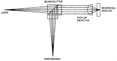
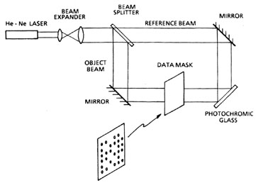
(107)The first part of the experiment illustrates the principle of optical storage, readout, and erasure of data. The material to be used for data storage is a photochromic glass. This is a fairly simple optical storage material compared to some other materials described in the discussion. However, most of these materials are difficult to work with. The choice of photochromic glass will allow principles of optical information storage to be demonstrated without undue experimental difficulty. (108)The photochromic glass that will be used is a borosilicate glass containing silver halide crystallites. One attractive feature of using photochromic glass is a well-defined wavelength separation for the three functions of writing, reading and erasing. When the material is exposed to blue light, the material darkens. If the glass is exposed to red light, the reverse process takes place. The darkened glass becomes clear and regains its original transparency. Between the two dominant wavelengths for coloring and for bleaching, a neutral wavelength can be found that has very little effect on the optical absorption of the photochromic glass. This wavelength can be used for readout. (109)The process that will be used is as follows: The glass will be colored by a uniform exposure to a helium-cadmium laser operating in the near-ultraviolet at 325 nm. If a helium-cadmium laser is not available, the glass may alternatively be colored by exposure to a mercury ultraviolet lamp. In fact, the glass even can be colored by exposure to sunlight, with filtering to remove the wavelengths that bleach the glass. The activation requires approximately 1 joule/cm2. So, if the helium-cadmium laser is operating at a total output of one milliwatt and one square centimeter of material is used, it will take approximately 1000 seconds or 17 minutes for full coloration. (110)The writing process occurs with red light. For this, we use the helium-neon laser. The setup is shown in Figure 12. The mirrors are mounted on gimbal mounts that are adjusted so that the object beam and reference beam overlap on the photochromic glass. It is important to adjust the apparatus so that equal path lengths are traversed by the reference beam and by the object beam.
Fig. 12
(111)This is a conventional holographic setup, except that the object of which the hologram is formed is a mask with an array of pinholes. See the inset in Figure 12. Light passing through positions on the mask where the pinholes are open can represent ones. Areas on the mask where the pinholes are not open can represent zeros. So, the mask could represent an array of bits. The fringe pattern is formed on the photochromic glass, which has been previously darkened. The glass will bleach in positions where the light intensity is high, thus recording the hologram. It’s important to monitor the exposure carefully. The energy required to bleach the glass and form the hologram is also approximately one joule/cm2. If the exposure is allowed to go too long, the entire glass will become bleached, and the hologram will be washed out. (112)The hologram can be read out by shining the argon laser operating at 514.5 nm along the same direction as the reference beam. See Figure 13. This wavelength has no effect on coloration or on bleaching of the glass.
Fig. 13
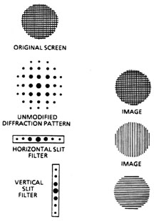
(113)The hologram can be viewed by eye. To make quantitative measurements, use a lens to form the image. Mount the PIN photodiode on the three-axis positioner and move it through the light pattern. Record the intensity of the maximum for each one bit. Record the light intensity reaching the position of the zero bits. The filter placed in front of the PIN diode will make it relatively insensitive to light other than that from the argon laser. Determine the contrast ratio between the one bits and the zero bits. The contrast ratio is the light intensity corresponding to the one bit divided by the light intensity corresponding to a zero bit. (114)When this procedure is completed, the hologram can be erased by the helium-cadmium laser beam operating at 325 nm. Illuminate the glass so it becomes uniformly colored again. (115)In this procedure, we have gone through the process of recording an array of bits, which could in principle represent information that is to be stored. We then have read out the information by reconstructing the holographic image. We finally have erased the hologram and will be ready to record a different pattern of bits on the same material. (116)The second part of the experiment involves a filtering operation to modify the image of a fine-mesh screen. This experiment is relatively simple in concept. But it will show how the principles of optical data processing operate. (117)The experimental arrangement is shown in Figure 14. The object is a screen with a fine mesh. It is illuminated by the HeNe laser. In the focal plane of the first lens, the diffraction pattern of the mesh appears. This is a two-dimensional array of bright spots. This is shown in Figure 15. The original mesh is shown at the top; its diffraction pattern is below it. When the image is reformed, by the second lens, an image of the original mesh can be projected on a screen.
Fig. 14
Fig. 15
(118)The power of the filtering techniques is illustrated by inserting a narrow slit in the focal plane only a single row of spectral components. The slit is mounted on the three-axis positioner and the slit position is adjusted so that only a single horizontal row of the diffraction pattern is transmitted. These bright spots correspond to the components of the screen that were oriented vertically. The image now contains only the vertical structure of the screen. Suppression of the horizontal structure is quite complete. This is shown in the third line of Figure 15. (119)Then the slit is rotated 90° , and positioned to transmit only a vertical row of spots, as shown in the fourth line of Figure 15. The image now contains only the horizontal structure. This is because the bright spots along a vertical axis arose from the horizontal lines in the original mesh. 
Arbach, J.C.; T.S. Fisli; and G.K. Starkweather. "Laser Scanning for Electronic Printing," Proceeds of the IEEE 70, August 1986. Beiser, L. "Laser Scanning and Recording: Developments and Trends," Focus, p. 88, February 1985. Bell, J.E. "Optical Computing, A Field in Flux," IEEE Spectrum, p. 34, August 1986. ___. "Holographic Scanning—A Maturing Movement," Electro-Optics. p. 20, February 1983. Bulthuis, K. et al. "Ten Billion Bits on a Disk," IEEE Spectrum, p. 26, August 1979. Buzzard, R.J. "Gas Lasers for Recording and Information Handling—A Review," Optical Engineering 15, 77, March-April 1976. Cavrioto, J. "Laser Printers—A Status Report," Lasers and Applications, p. 69, October 1984. Cunningham, R. "Erasable Optical Storage Moves Forward," Lasers and Applications, p. 109, May 1984. Dunn, S.T. "Update on Laser Reprographics," Lasers and Applications, p. 47, October 1983. Grenda, E. "Scanning Subsystems: First and Final Choices," Laser Focus, p. 149, October 1985. Hecht, J. "Optical Data Storage, A Status Report," Lasers and Applications, p. 69, June 1983. Hudgens, S.J. "Amorphous Silicon Photoreceptors for Laser Printers," Lasers and Applications, p. 99, September 1985. Kenville, R. F. "FifteenYears of Laser Recording—Where We’ve Been and Where We’re Going," Optical Engineering 20, 330, May/June 1981. Kramer, C.J. "Holographic Laser Scanners for Nonimpact Printing," Laser Focus, p. 70, June 1081. Kuntz, D. "Specifying Laser Diode Optics," Laser Focus/Electro-Optics, p. 44, March 1984. Laub, L. "Design of Optical Storage Products," Laser Focus, p. 74, June 1985. ___. "Design of Optical Storage Products, Part Two," Laser Focus, p. 104, September 1985. Lewis, J.R., and L.M. Hubby, Jr. "The Hewlett-Packard Laser Printer, A Case Study," Lasers and Applications, p. 49, November 1982. McAulay, Alastair D. "Optical Computer Architectures: The Application of Optical Concepts to the Next Generation of Computers." Ready, J.F. Industrial Applications of Lasers, Chapter 21. New York: Academic Press, Inc., 1978. Optical Data Processing Applications. Casasent, D. Editor. Berlin and New York: Springer-Verlag, 1978. Sonnenberg, H. "Designing Scanners for Laser Printers," Lasers and Applications, p. 67, April 1983. Tebo, A. "Writing with Diode Lasers," Electro-Optics, p. 56, June 1983. --------------------------------------------------------------
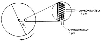
|
|||||||||||||||||||||||||||||||||||||||||||||||||||||||||||||