| This version reflects the comments of the core participants as reviewed and incorporated in accordance with CORD's FIPSE-supported Curriculum Morphing Project. | |||||||||||||||||||||||||||||||||||||||||||||||||||||||||||||||||||||||||||||||||||||||||||||||||||||||||||||||
MODULE 8 Changes in red were made as a group by Pete Latham–course director, Yoriko Morita, Nick Massa and Tung Jeong. (1)Laser communication systems are used to transfer information from one point to a distant point. The information may be an audio conversation, a stream of data from one computer to another, or several simultaneous television broadcasts. The distance may range from a few feet to thousands of miles. (2)Optical communication systems in the past consisted of techniques such as fire signals, smoke signals, flash lanterns, reflected sunlight and signal flags. Such systems had limited bandwidth and were not competitive with electronic communications (like radio). (3)The invention of the laser provided a coherent optical source capable of transmitting information at extremely high data rates. However, limitations on transmission of light through the atmosphere (such as turbulence, haze, fog, absorption and rain) limited the usefulness of lasers for transmission of information through the atmosphere. Modern optical communication systems use semiconductor lasers that transmit light through optical fibers. Such systems have become widely used for telecommunications. (4)In this chapter, you will learn about the components used in fiber-optic laser-based telecommunication systems, the trade-offs in the choice of components for systems and the applications of fiber-optic communications. (5)Before beginning this chapter, you should have studied semiconductor lasers, optical fibers and photodetectors. You also should have knowledge of laser safety practices, and enough math background to understand logarithms.
Upon completion of this chapter, you should be able to do the following: 1. Describe, in terms similar to the text, the elements of a fiber-optic telecommunication system. 2. Describe three causes of signal degradation in fiber-optic systems. 3. Describe the trade-offs between price and performance in choosing components for a fiber-optic communication link. 4. Discuss the factors that affect the choice of wavelength for a fiber-optic communication system. 5. Perform calculations related to fiber-optic system performance. 6. Describe at least three applications for fiber-optic telecommunication systems. 7. State why fiber-optic telecommunications are used instead of free atmospheric propagation of laser beams. 8. List three advantages of optical fiber as compared to copper wire for communications. 9. Perform experimental procedures involving coupling of light into fibers, detection of light transmitted through fibers, measurement of loss in fibers, and measurement of loss introduced by connectors. DISCUSSION Optical-fiber Telecommunications (6)Optical communication has a long history, dating back to signal fires in ancient times. Optical communication reached a peak in the 1800s with the use of the heliograph for signaling during military operations in the American southwest. In the late 1800s, electronic communication developed very rapidly, and virtually eliminated interest in optical communication for many years. (7)By the middle of the 20th century, the electronic communication system had become very crowded. The radio spectrum was virtually filled. Telephone lines were heavily loaded, especially in large cities. The cost of adding new telephone lines in urban areas was very high. When the laser was invented in 1960, interest in optical communication was revived. (8)The invention of the laser made it possible to build optical communication systems with significant advantages: 1. Very high concentration of optical power and very little spread of that power with distance (low beam divergence). 2. Ability to carry huge amounts of information (high information bandwidth). 3. Small antennas required (compared to radio-frequency communication systems). 4. Narrow spectral linewidth, allowing the rejection of light except at the laser wavelength. 5. Coherence, allowing use of techniques such as frequency modulation and superheterodyne detection, which have been extremely useful in electronic communication. (9)Because of these characteristics, useful information can be impressed on a beam of light, and transmitted to a remote location, where the information can be recovered. There was great initial interest in optical communication based on laser beams transmitted through the atmosphere. However, this type of optical communication system has not attained wide use because of the nature of the atmosphere. The atmosphere often can be turbulent, causing beam wander and scintillation. Molecular absorption bands cut off some wavelengths completely. Scattering by haze and dust is also a problem. Poor weather conditions, like fog, clouds, and rain, might shut down a communication link completely. So, only a few laser-based communication systems have been developed for free atmospheric propagation. (10)Optical fibers offer an attractive alternate choice for a transmission medium to eliminate problems with atmospheric transmission. Thin optical fibers can be fabricated with lengths of many kilometers. A light beam coupled into one end of the fiber can propagate through the fiber without atmospheric interference, and can be detected at the other end of the fiber. Figure 1 shows the structure of a fiber. It has a core surrounded by a cladding with lower index of refraction. The numerical aperture (NA) is defined as NA º sin a max where a max is the angle between the incident light and the fiber axis. The NA is a measure of how much light can be coupled into the fiber.
Fig. 1
(11)In practice, laser based communications are dominated by fiber-optic transmission. A fiber-optic telecommunication system is used to transfer information (such as conversations, TV pictures, telemetry data) over some distance. The optical communication system is generally similar to conventional radio-frequency (RF) systems or closed-circuit systems from the standpoint of intended usage. However, the way the transmission is accomplished differs in several respects. This chapter will describe briefly the areas of concern in communication systems in general. It will emphasize those characteristics of the communication system that are peculiar to optical (or laser) communication. In addition, it will emphasize the systems aspects of fiber-optic communication systems. It assumes that the principal components (lasers, fibers, and detectors) are familiar to the student. (12)The laser used in fiber-optic telecommunication systems is the semi-conductor laser. Semiconductor lasers are especially well-suited for use in this type of communication system. Semiconductor lasers have suitably small size and configuration for coupling into the small-diameter core of an optical fiber. Modern AlxGa1–xAs lasers operate continuously at milliwatt power levels sufficient for fiber-optic communications. They can be modulated easily, through modulation of an electric power supply, at frequencies up to the gigahertz range. This makes it possible to transmit information, by modulating a beam of light from a laser, through optical fibers. The semiconductor laser, with its small emitting area, is a natural choice as a source for fiber communications. But for a number of years, laser lifetime was too short and fiber losses too high to make laser-based fiber communications a success. (13)The status of both lasers and fibers has advanced considerably, with both fiber loss and laser lifetime undergoing improvements by factors of ten. Figure 2 shows the improvement of these parameters over the years. Before laser-based fiber-optic telecommunications could be regarded seriously, laser lifetime had to reach 105 hours or more, and fiber loss had to be reduced to a few dB/km or less. Both these levels were reached by the late 1970s. In recent years, fiber-optical telecommunication systems have become practical realities, carrying information for intracity telephone links, telephone trunk lines, video data links, and information links between computers.
Fig. 2 Editor's Note: Figure 2 schematically
represents that
(14)The loss in optical fibers is expressed commonly in terms of the number of decibels (dB) loss per kilometer of length of the fiber. (15)Loss in decibels is described on a logarithmic scale. If a signal P0 is input to a fiber and a signal P is transmitted, the loss in decibels is expressed as dBloss = 10 log10 ( P0/P) So, ten decibels corresponds to a decrease in signal level by a factor of 10, twenty decibels by a factor of 100, etc.
(16)A common nomenclature associated with optical-fiber telecommunication is that of lightwave and waveguide. Lightwave refers to the components used to generate and receive the light (lasers, detectors, etc.). Waveguide refers to the media through which the light is transmitted (fibers, connectors, and so on). (17)A basic fiber-optic telecommunication link is shown in Figure 3. The laser output is modulated to yield a digital pulse-code-modulated (PCM) signal, that is, a series of ones and zeros. The input signal drives the laser power supply (the driver), which in turn pulses the laser on and off. The light from the laser is coupled into the fiber. The end of the fiber is positioned by a connector to maximize the input. This part of the system constitutes an optical transmitter. (18)The fiber carries the light toward the receiver, where the light is detected and the digital signal is recovered. But the link may be long, perhaps many kilometers. Absorption, scattering and dispersion in the fiber may degrade the signal. Optical amplifiers are needed to regenerate the signal every 50 to 100 km. Early fiber-optic telecommunications systems included signal repeaters that consisted of a detector, amplifier, and a signal regenerator that restored the shape and intensity of the pulses. In the more modern networks, the repeater system is replaced by an optical amplifier which consists of laser gain material and replicates and reinforces the signal optically.
Fig. 3
(19)Several repeaters may be needed between the original source and the final receiver. Current technology usually requires repeaters every few kilometers. The distance between repeaters is an important parameter that affects the cost and practicality of a fiber-optic communication system. (20)At the end of the fiber is the receiver, which consists of an optical detector that detects the light and turns it back into an electrical signal, plus an amplifier and regenerator that restore the pulse shape. The output is a PCM train of digital information, the same as the input at the transmitter. (21)Figure 3 also shows a splice. It’s important for installation and for repair to be able to cut fiber cables and to splice them. Low-loss splices for optical cables have been developed. These splices can be used successfully to repair cables in the field. A splice may add a loss of around 0.2 dB to the system. (22)Fibers are available as multifiber cables with protective coatings, metal strands for strength and outside covers. Multifiber stranded cables, for example, include interwoven strands of 1 to 16 fibers. Multifiber ribbon cables are based on ribbons manufactured by packing fibers between adhesive-backed plastic tapes. Such ribbons can contain up to 140 fibers. (23)Cables can be obtained complete with connectors that allow simple plug-in connection to optical components or to other lengths of cable. Such connectors are available with a loss of only a few tenths of one decibel. High-quality multifiber cables and connectors are manufactured in large volume. (24)To understand the factors that affect the design of fiber-optic communication systems, we first describe the causes of signal degradation in these systems. (25)Fiber-optic telecommunication systems use pulse code modulation. This means that the information is transmitted as a series of pulses that represent binary bits of information—that is, ones and zeros. The presence of a pulse in a given time interval will represent a one. The absence of a pulse represents a zero. Information can be lost if the amplitude of the pulse becomes so small that it cannot be detected, or it can be lost if the pulse shape becomes spread out so that it does not fall within the proper time interval. In either case, the information represented by the pulse cannot be received by a receiver looking within the specified time interval. (26)Causes of signal degradation are shown in Figure 4. The top part of the figure represents what is commonly called attenuation or fiber loss. The intensity of the light pulse decreases as the pulses travel along the length of the fiber. This is the number that usually is expressed in terms of decibels per kilometer. Fiber loss will decrease the amount of light that is available for the receiver, but it does not cause the signal to move out of its proper time interval.
Fig. 4
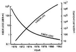
(27)The lower part of the figure shows two mechanisms of signal degradation that do not involve loss of light intensity, but that do cause the pulse to broaden and to move out of its time slot. (28)The first, called modal dispersion, results from the fact that light can travel along different paths down the length of the fiber. This means that the initial short pulse will be broadened, and will spread out of its time slot. (29)The second, called chromatic dispersion, results from the variation of index of refraction with wavelength, so that light of different wavelengths travels through the fiber at different velocities. (30)We now discuss these three causes of signal degradation and their effect on system performance.
Fiber Loss (31)The loss in optical fibers is dominated by impurities in the silica-based materials that are used for fabricating fibers. The effort to reduce fiber loss has been primarily an effort to reduce impurities. (32)The curve that represent loss versus wavelength in high-quality modern silica fibers is shown in Figure 5. There are three regions of local minima in the fiber loss, near 0.85 m m, 1.3 m m and 1.55 m m. At shorter wavelengths, the loss increases due to Rayleigh scattering. At longer wavelengths, it increases due to infrared photon absorption. The typical low loss fiber has a minimum loss near 0.1 dB/km at 1.55 m m. Note that some newer types of fiber remove the peak near 1.4 mm.
Fig. 5 Note
that Fig 5 is an example of one type
of fiber. Some newer types of
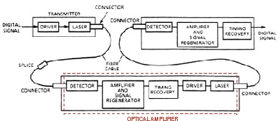
(33)Historically, as fibers with higher purity were being developed, the window at 0.85 m m was opened first. This matched the wavelength of available AlGaAs lasers. The first practical fiber-optic systems used this wavelength. Later, as the fiber fabrication process was further improved, lower-loss windows were opened, first at 1.3 and later at 1.55 m m. These wavelengths are preferable for high-performance long-distance systems because of the lower fiber loss. The following nomenclature is common in referring to the different windows:
(34)Table 1 shows the components that commonly are used for systems operating in each of these windows. Table 1. Definitions
Modal Dispersion (35)Modal dispersion is the presence of multiple modes in fibers, so that light can travel through the fiber by different paths. The situation is sketched in Figure 6. (36)Multimode fibers, shown at the top of the figure, have a relatively large-diameter core. They offer high values of numerical aperture and easy coupling of light into the fiber. However, as the figure shows, many modes can propagate in such fibers, so that a short pulse of light injected into the fiber will broaden due to the variations in path length. So, multimode fibers such as this have limited bandwidth, or limited data rate. They are useful only in short-haul, low-performance systems. (37)Single-mode fibers, shown in the center of the figure, have small core diameters. They have small dispersion because light can propagate only at small angles to the axis. So there is less spread in the possible path lengths down the fiber and relatively little distortion of short pulses. Such fibers can be used for systems with large bandwidth. They require greater precision in fabrication, and efficient coupling of light into them is more difficult.
Fig. 6
(38)As shown in the bottom of the figure, fibers with graded index of refraction offer a compromise. A parabolic radial variation of the index of refraction acts like a continuous focusing element. Rays traveling at an angle to the axis are bent back toward the axis by the gradient in refractive index. A ray traveling at an angle to the axis travels farther than one along the axis, but it spends more time in regions with low index of refraction. So it has higher average velocity than the axial ray. The choice of the parabolic profile tends to keep the different rays in phase, and dispersion is small. Because of the relatively large core, coupling is relatively easy. (39)Both graded-index fibers and single-mode fibers are available for use in modern long-haul, high-performance systems.
Chromatic Dispersion (40)The final cause of signal degradation, chromatic dispersion, is shown in Figure 7. The top part of the figure shows dispersion versus wavelength. The dispersion is expressed in picoseconds of pulse delay per kilometer of fiber length, per nanometer of bandwidth of the source. (41)The lower part of the curve shows the effect of dispersion. The short-wavelength ("blue") components of the laser spectrum will arrive at the end of the fiber first, and the long-wavelength ("red") components later. The short input pulse thus will be spread out in time after it traverses the fiber.
Fig. 7
(42)Note that chromatic dispersion becomes more serious as the spectral width of the source increases. So it is important to use sources with very narrow spectral bandwidth. (43)Also, the chromatic dispersion has a value near zero at a wavelength of 1.3 m m. This makes the chromatic dispersion problem disappear if this wavelength is selected for operation. Thus, operation in the "second window" can be especially favorable.
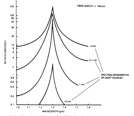
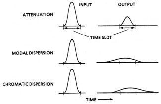
Effects of Signal Degradation on System Performance (44)The maximum rate of data transmission in a single-mode fiber-optic communication system is determine primarily by chromatic dispersion. Figure 8 shows the theoretical maximum transmission bandwidth (i.e., the maximum bit rate) for a 100-km-long fiber, for four different sources with the indicated spectral bandwidths. The four curves represent sources with the indicated spectral widths. Again, the importance of using a source with narrow spectral widths is clear.
Fig. 8
(44)The data transmission rate can be very high, many gigabits/second. (45)Figure 9 shows results of long-distance transmission experiments conducted in laboratories in the United States, United Kingdom and Japan. The solid lines show the theoretical limits imposed by fiber loss (0.2 dB/km assumed) and by dispersion, for lasers with the indicated spectral widths. The solid lines are theoretical limits imposed by fiber loss and by dispersion. For the dispersion limits, assumed spectral widths for the source are indicated. The points represent experimental results. (46)It is clear that the experiments, as indicated by the points, can approach the theoretical limits. Bit rates of several gigabits per second over distances of tens of kilometers have been achieved.
Fig. 9
Choice of Components for Fiber-optic Systems (47)Table 2 describes the components used in fiber-optical systems. The losses for fibers are those of production fibers. Experimental fibers with lower losses have been demonstrated. Laser sources offer high performance, but LED sources may be suitable as lower-cost sources in systems that require lower performance. (48)Most existing systems use AlxGA1–xAs source (either lasers or LEDs) operating near 0.85 m m. Such systems are termed "short-wavelength" systems. There is much interest in InGaAsP sources operating near 1.3 m m and 1.55 m m. These are called "long-wavelength" systems. The long wavelengths have two advantages: The loss in optical fiber is lower than at 0.85 m m, and the dispersion (the variation of refractive index with wavelength) is near zero. Despite the advantages, long-wavelength fiber-optic systems are not yet widely used, because the sources are less well developed than AlxGA1–xAs sources. However, experimental work is emphasizing long-wavelength systems, and we may expect that future installed fiber-optic systems will be dominated increasingly by long-wavelength devices. Table 2. Typical Components for Fiber-optic Systems
(49)Table 3 lists typical properties of sources that could be chosen for use in fiber-optic systems. Table 3. Typical Selected Semiconductor Sources
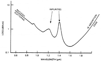
(50)Some properties of commercially available fibers are illustrated in Table 4. An important parameter is the distance-bandwidth product, expressed in MHz-km. This gives the product of the maximum data-transmission rate and the maximum distance between repeaters. It is a common figure of merit used to characterize system performance. Table 4. Types of Fibers
(51)The detectors are another important part of the system. Detector technology is well developed. For AlxGA1–xAs sources, silicon photodiodes are suitable detectors. Silicon photodiodes offer excellent high-frequency response at wavelengths to 1.1 m m. They have peak spectral response near 0.9 m m, close to the wavelength of AlxGA1–xAs lasers. At longer wavelengths, in particular at 1.3 m m, silicon photodiodes are no longer useful. For long-wavelength (i.e., 1.3-m m) fiber-optic systems, germanium or InGaAsSb photodiodes must be used. However, they are less well developed than silicon photodiodes. (52)Detectors for fiber-optic communications systems are of two types, either PIN or APD. The PIN construction features a layer of P-type material, a layer of Intrinsic silicon, and a layer of N-type material. So the initials PIN are used. The APD detector is an Avalanche PhotoDiode, which features a high applied voltage. When light is incident on the APD, an avalanche of impact ionization is produced by high-energy carriers, so the APD delivers a large signal. (53)The detectors are characterized by a parameter called responsivity. Responsivity is the amperes of electrical current output per unit of optical power input. The APD offers better performance (that is, higher responsivity) but at higher cost, than the PIN photodiode. (54)The receiver used for detection of the light and recovery of the information contains a detector, which converts the received optical energy to an electrical signal, and the electronics to convert the detector output to a usable electronic signal. (55)Even though the detector has provided an adequate signal voltage corresponding to the received optical signal, care must be exercised in the electronic circuitry that follows the detector if optimum system performance is to be realized. (56)The first stage of amplification following the detector, called the preamplifier or, more commonly "preamp," is especially important. Any external noise introduced at the preamp will be amplified in succeeding stages, and will degrade ultimate system performance. In most cases, the detector and preamp are located as close to each other as possible to reduce the amount of interference or noise picked up in this stage. (57)Random fluctuations in the output of the receiver are called noise. Noise can be categorized on the basis of its source. Noise may be associated with the optical signal itself. For example, if dispersion causes part of the pulse energy to spill over into the time slot for another pulse, this will represent a source of noise. Other types of noise are generated by the detector and the detector load resistor. A third type of electronic noise is that induced by amplifiers in the receiver. (58)One measure of the performance of an optical communication system is the magnitude of the signal in comparison to the noise. This is expressed as the signal-to-noise ratio (SNR). SNR is calculated from the formula: SNR = (59)In digital communication systems, a different figure-of-merit is also used. It is called the bit error rate (BER). The BER is the ratio of the number of wrong decisions made by the receiver to the total number of decisions made or BER = (60)In practical modern optical communication systems, bit error rates less than 10–9 are desired. (61)Figure 10 shows sensitivities for state-of-the-art optical receivers, plotted as a function of bit rate. The sensitivity represents the number of photons required to achieve a bit error rate of 10–9. Sensitivities are given in terms of the average number of signal photons per bit to achieve a bit error rate of 10–9. The bands show expected performance for APD and PIN receivers. The dots and squares represent experimental results for PIN devices and APD devices, respectively.
Fig. 10
Trade-offs in Optical Systems (62)Now let us consider trade-offs that may be made in the choice of components for a system. Table 5 summarizes performance versus cost tradeoffs in the design of a fiber-optical telecommunication system. Systems that require relatively low bandwidth and/or short distances between repeaters may use low-cost components: LEDs, PIN photodiodes and multimode fibers. These components are adequate for systems that operate with a bandwidth-distance product less than 100 MHz-km, higher-cost components (laser diodes, APDs as detectors and single-mode fibers) should be used. Table 5. Performance/Cost Trade-offs
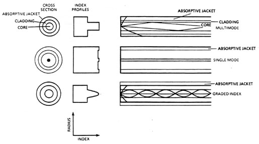
(63)Table 6 illustrates the trade-offs for the choice of the wavelength of a system. Most operating systems now operate at 0.85 m m. But for high performance future systems, the dominant factor may be fiber loss, which is lowest at 1.55 m m. We can expect most high-performance systems to operate at one of the longer wavelengths. Table 6. Wavelength/Performance Trade-offs
Applications (64)The most important application of fiber-optic laser-based communication is in long-distance telecommunications, that is, the communication market serviced conveniently by telephone lines, microwave relays, etc. (65)Fiber-optic systems offer many advantages, such as:
(66)Fiber-optic systems have data rates of hundreds to thousands of megabits per second over distances of tens of kilometers. This represents extremely high information capacity in links that are smaller, lighter and less expensive than copper wire. (67)Table 7 compares some characteristics of optical fibers and copper wire. The advantages of the optical fiber are clear. In addition, optical fiber is immune to interference from electrical transients, electromagnetic pulses and radio-frequency interference. Table 7. Characteristics of Cables Based
(68)Today, there are hundreds of thousand of miles of fiber-optical telecommunication links in use in the United States and other countries. Fibers are used for intracity telephone links, where bulky copper wire is being replaced by thin optical fibers. This allows crowded conduits in large cities to carry more messages than if copper wire were used. Fiber optics is used for intercity long-haul telephone links, and is beginning to replace microwave communication links. (69)Figure 11 shows data rate and repeater length for some installed
optical-fiber communication systems. These example, taken from both
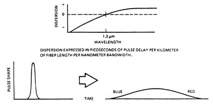
the United States and Europe, are not a complete enumeration of existing
systems. Rather the figure shows that many optical-fiber telecommunication
systems with varying capabilities are in use. Systems with small values
of distance bandwidth product usually use LEDs (systems denoted by
Fig. 11
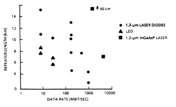
(70)Two systems, denoted by squares, that use 1.3-m m InGaAsP sources are also included. These are examples of even higher values of distance bandwidth product. One is a 6-gigabit/second link in Hawaii. The other is a 1.7-gigabit/second system in a Philadelphia-to-Chicago intercity link. (71)Optical-fiber communications are useful not only for long-distance communication links. Fiber-optic data links are used also in a variety of short-distance systems, for example in computer-computer links and for internal communications on ships and aircraft. One example is a fiber-optic auxiliary communication and navigation system used in the Harrier fighter/bomber. The use of fiber optics saves weight as compared to copper wire and is not vulnerable to electromagnetic interference. Both of these features are important for military weapon systems. (72)Figure 12 shows some possible applications for fiber-optic communications with respect to length and bit rate. The common carrier applications, like telephone links, lie to the upper right of the dashed line labeled 100 MHz-km. However, a wide variety of other lower-performance applications, illustrated to the lower left of the dashed line, are under investigation.
Fig. 12
(73)These applications include many of the shorter-distance communication links (e.g. computer-to-computer data links, or automated operation of all the environmental controls in a large commercial building). Fiber optics can replace copper wire at a savings in space and cost for many of these applications. (74)This chapter cannot discuss in detail all applications shown in Figure 12. We will emphasize only one, that of local area networks (LAN). (74)A LAN is an arrangement of hardware to interconnect a variety of communication functions concentrated in a small localized area. The maximum distance between any two points in the LAN may be no more than a few hundred meters. A LAN may be within a single building, or among several buildings. Figure 13 shows an example.
Fig. 13
(76)Figure 13 also shows a common arrangement of a LAN, that is, several pieces of equipment connected to a common node and the nodes interconnected through so-called STAR couplers. A STAR coupler shares its inputs from any node equally among all outputs. (77)The use of fiber optics to replace copper wire in LANs is at an early stage. But it is beginning to grow. This will be an important area for fiber-optic communication in the future. (78)In summary, the use of fiber-optic communication has become extremely widespread, especially for long-distance communications. And it’s rapidly spreading into other applications.
1. Describe the elements of a fiber-optic telecommunication system. 2. Describe three causes of signal degradation in a fiber-optic system. 3. Describe the trade-offs between price and performance in choosing components for a fiber-optic communication link. 4. Discuss the factors that affect the choice of wavelength for a fiber-optic communication system. 5. A fiber-optic communication system is being designed to operate at a wavelength of 0.85 m m with fiber that has a loss of 2 dB/km, and a receiver that can detect signals at 43 dBm. The system must operate over a distance of 23 km without a repeater. How much laser power must be coupled into the fiber? 6. Describe at least three applications for optical-fiber telecommunication links. 7. State why fiber-optic communications are used instead of free atmospheric propagation of laser light. 8. List three advantages of optical fiber as compared to copper wire for communications.
Optical fibers:
Fiber-optic power meter; EG&G model 780 or equivalent Photodetector; United Detector Technology PIN-5 photodiode or equivalent Laser source and power supply; AT&T ODL 200 transmitter or equivalent Micrometer-driven x-y micropositioner Battery (6 volt) Resistor (106 ohm, 1/4 watt) Oscilloscope Optical bench or rail with mounts and holders or clamps
Before starting this experiment, you should review safety guidelines necessary when dealing with optical and electrical hazards. You should use extreme care in handling the various photodetectors and avoid exposure of these devices to unusually high intensities of illumination. Have the instructor check your setup before you start the experiment. The first part of the experiment involves measurement of the coupling of optical signals into a fiber and detection of the signals transmitted through the fiber. 1. Set up the apparatus as shown in Figure 14. The fiber should be the piece of fiber without connectors. The fiber will be held in a clamp or mount attached to the x-y micropositioner. The micropositioner will be mounted on a holder on the optical bench. The end of the fiber is held in the clamp and positioned as close as possible to the end of the laser diode. The diagram for the wiring of the photodetector is shown in the inset.
Fig. 14
2. Turn on the laser diode, with the power supply delivering short pulses to the diode. Observe the pulses received by the detector, using the oscilloscope. 3. Move the end of the fiber by moving the micrometers on the x-y translation stage, so that the end of the fiber is displaced with respect to the laser beam. Observe the decrease in received signal level, as shown on the oscilloscope, as the end of the fiber is displaced. 4. Plot the received signal level versus position of the end of the fiber. What does this result imply about the need for careful alignment of the fiber and the laser? The next part of the experiment involves measurement of fiber loss. First, you will measure the amount of light transmitted through a short fiber as a reference. Then you will measure the amount of light transmitted through a long fiber. 1. The apparatus is the same as in Figure 14, except that the detector is replaced by the power meter. In this part of the experiment, use the fiber with connectors. Align the fiber end for maximum power received by the power meter. 2. Turn on the laser. Measure the power transmitted through the short reference fiber. 3. Replace the short fiber with the long fiber. Measure the power transmitted through it. 4. Calculate the total loss of the long fiber in dB, and calculate the loss in dB/km. In the calculation, use the results from Step 2 as a reference to determine how much light was lost by coupling into and out of the fiber. The final part of the experiment involves measurement of loss of a connector. 1. Measure the loss of two separate long pieces of fiber (with connectors) as described in the second part of the experiment. 2. Connect the two fibers and measure the loss through the two connected fibers. 3. Any additional loss, above the sum of the losses of the two separate fibers, must have come from the connector. Calculate the loss (in dB) introduced by the connector.
Aslami, M., and C. DeLuca. "Practical Considerations in Selecting Optical Fibers," Laser Focus, 110, August 1984. Buijs, N. A., and A. J. M. Dingjan. "Improving Repeater Spacing in Fiberoptic Systems," Lasers and Applications, 95, May 1984. Chaffee, C. D. "Fiberoptics in Long-haul Nets, The Market Reaches Its Peak," Laser Focus, 116, October 1986. ___. "U.S. Military Programs Take Advantage of Fiberoptic Technology," Laser Focus, 80, August 1986. Charlton, D. "Market Trends in Optical Fiber Products," Laser Focus, 98, September 1984, and following articles. Chen, B. U. "Integrated Transmitter and Receiver Modules Provide High Speed Communications," Laser Focus, 176, April 1987. Cheo, P. K. Fiber Optics: Devices and Systems. Englewood Cliffs, NJ: Prentice Hall, 1985. Cook, J. "Making Low-loss Single-mode Connectors," Laser Focus, 123, October 1983. Daly, J. C., Editor. Fiber Optics. Cleveland, OH: CRC Press, 1984. Fye, D. M. "Diode Lasers vs. LEDs in the Single-mode Fiber System, A Vote for LEDs," Lasers and Applications, 47, January 1987. Gordon, E. I. "Components Show Increasing Sophistication with Trend to Single-mode Transmission," Laser Focus, 148, October 1985, and following articles. ___. "Diode Lasers vs. LEDs in the Single-mode Fiber System, A Vote for Diode Lasers," Lasers and Applications, 43, January 1987. Hecht, J. "Single-mode Fibers Go to Market," Lasers and Applications, 54, May 1983. ___."Fiberoptic Test Equipment Survey," Lasers and Applications, 63, October 1983. Hornung, E. "Repeaterless Undersea Cable Communications in Denmark," Laser Focus, 134, June 1986. Jay, J. A. "Narrow-linewidth Lasers and Dispersion-shifted Fibers, A Promising Combination," Laser Focus, 104, July 1987. Jeunhomme, L. B. Single Mode Fiber Optics: Principles and Applications. New York: M. Dekker, Inc., 1983. Kao, C. K., Editor. Optical Fiber Technology II. New York: Institute of Electrical and Electronic Engineers, 1981. Kessler, J. N. "The Future for Fiberoptics Promises Integrated Services for Consumers," Laser Focus, 172, October 1984, and following articles. Kritler, D. A. "Optical Fiber Bandwidth Measurement: Standards and Reproducibility," Laser Focus, 114, January 1987. Lasers and Applications Staff. "Fiberoptic Connector Matrix," Lasers and Applications, 64, September 1984. Lasers and Applications Staff. "Fiberoptic Connector Specification Table," Lasers and Applications, 124, September 1985. Lasers and Applications Staff. "Fiberoptic Test Equipment Specification Table," Lasers and Applications, 59, December 1985. Lemrow, C. M., and V. A. Bhagovatula. "Advanced Fiber Designs," Laser Focus, 82, March 1985. Li, T., Editor. "Advances in Lightwave Systems Research," AT&T Technical Journal 66, 5, 1987, and following articles. ___. Optical Fiber Communications, Volume 1. New York: Academic Press, 1985. Maiolo L., and R. Coulombe. "Fiberoptic Cable Assemblies: Deciding to Make or Buy," Laser Focus, 90, August 1985. Miller, S. E., and A. G. Chynoweth, Editors. Optical Fiber Telecommunications. New York: Academic Press, Inc., 1979. Nicholson, P. J. "Fiberoptics for Multiple-service Local Area Networks," Laser Focus,123, November 1983. Pyykkonen, M. "Fiber for LANs—The High-performance Alternative," Laser Focus, 104, March 1987. Rhea, J. "Fiberoptics Expands Design Potential for Weapon Systems," Laser Focus, 94, August 1987. Wendland, P. "Measuring Fiberoptic Power and Attenuation," Lasers and Applications, 67, February 1986. --------------------------------------------------------------
|
|||||||||||||||||||||||||||||||||||||||||||||||||||||||||||||||||||||||||||||||||||||||||||||||||||||||||||||||


 = 150 km