| This version reflects the comments of the core participants as reviewed and incorporated in accordance with CORD's FIPSE-supported Curriculum Morphing Project. | |||||
MODULE 10-6 INTRODUCTION The Twyman-Green interferometer is a very useful instrument for measuring defects in optical components such as lenses, prisms, plane-parallel windows, laser rods, and plane mirrors. The beam splitter and mirror arrangement of the Twyman-Green interferometer resembles that of a Michelson interferometer. The difference lies in the way the interferometers are illuminated. While the Michelson interferometer is used with an extended light source, the Twyman-Green interferometer is used with a monochromatic point source which is located at the principal focus of a well-corrected lens. This module will familiarize the student with the characteristics of Twyman-Green
interferometer. It will provide practical experience in aligning and using this
interferometer to test lenses, prisms, optical flats, and glass for imperfections or
optical inhomogeneities. MODULE PREREQUISITES The student should have completed Modules 1-1 and 1-8 of Course 1, "Introduction to Lasers"; Modules 7-1 through 7-8 of Course 7, "Laser Electro-Optic Devices"; and Module 10-4, "Michelson Interferometer." The student should also have a basic knowledge of interference of optical waves and lens aberrations, safety precautions applicable to low-pressure mercury vapor lamps, and be familiar with the 25-9093 Ealing Universal interferometer assembly.
Upon completion of this module, the student should be able to: 1. Demonstrate knowledge of a Twyman-Green interferometer by drawing and labeling a sketch of its basic design and elements. 2. Explain how the Twyman-Green interferometer operates, including the following items:
3. Convert a Michelson interferometer to a Twyman-Green interferometer, and align the interferometer using a low-pressure mercury vapor lamp according to procedures outlined in the text. 4. Assemble equipment and perform experiments according to given procedures to accomplish the following:

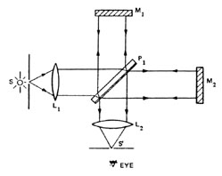
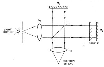
The Twyman-Green interferometer is basically a very simple device. A schematic diagram of the instrument and associated optical equipment is shown in Figure 1. The light from a nearly monochromatic point source S located at the principal focus of a well-corrected lens L1 is collimated and divided into two beams of equal intensity at the 50% reflecting surface of a plane parallel glass plate P1. Upon reflection at the plane mirrors M1 and M2, the beams are combined and brought to a focus at S1 by the second lens L2.
Fig. 1
To properly align the interferometer, both mirrors are adjusted with micrometer screws until the two images of S from mirrors M1 and M2 coincide with the light source at S, which is usually a very small pinhole. At the same time, the two images at the plane containing image S¢ will also coincide. With the mirrors adjusted in this manner, the superimposed plane waves from each mirror are exactly parallel. In addition, a constant phase difference between the recombined beams exists across the whole field of view. With the eye placed at the focus of lens L2, the observer will see uniform illumination across the entire field of view. The intensity of illumination depends on the path difference.
The intensity is maximum when the path difference is zero or differs by
an integral number of wavelengths; that is, when D m =
0, 1, 2, 3, ¼ etc. On the other hand, when D
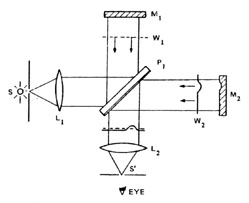
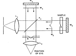
m = To summarize, when both mirrors M1 and M2 are perfectly flat and properly aligned, the recombined waves are strictly parallel. In this case, the field of view is uniformly illuminated and no fringes are observed. However, if there is a very small surface irregularity, such as a small valley or crest on one of the mirrors (i.e., on M2), the irregularity would lead to a localized fringe pattern that would look like a contour map. This result can be examined in more detail with the help of Figure 2.
Fig. 2
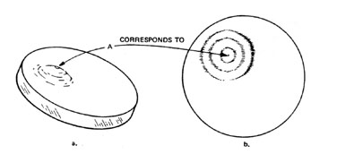
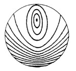
Since mirror M2 is assumed to have a slightly irregular surface, the emerging wavefront W2 is slightly deformed. With the eye at S¢ , the observer will see fringes which arise because of the interference between the plane reference wave W1 reflecting from the plane mirror M1 and the slightly deformed wave W2 reflecting from mirror M2. The observer will see bright fringes where the peaks of the two waves reinforce and dark lines where the troughs of the waves from one beam coincide with the peaks of the waves from the other beam. These fringes are the contour lines of the distorted wavefront, so that the imperfections of mirrors M2 are found at once in terms of the wavefront aberrations due to M2. As an example, consider the mirror shown in Figure 3a. The mirror shows an elevated region with the highest point at A. For illustration purposes, the height has been greatly exaggerated. The corresponding fringe pattern of such a mirror is shown in Figure 3b.
Fig. 3
A similar interference effect can be produced if the imperfect mirror is replaced with a perfectly plane mirror and an optically imperfect prism, or an imperfect lens and a perfect spherical mirror. The following experiments show how the Twyman-Green interferometer can be used to measure defects caused by inhomogeneities or polishing errors in optical components.
Ealing Universal interferometer (Model 95-9093) and all accessories Prism with optically worked faces, approximately 25 ´ 25 mm Glass plate of good optical homogeneity with parallel surfaces (one surface should contain a polishing error) Glass plate of poor optical homogeneity with parallel, plane surfaces Lens of poor optical quality with a focal length of approximately 15 cm Convex front surface spherical mirror of good optical quality with a radius of curvature of approximately 20 cm
Before beginning the experiments, the student should review the safety procedures that apply when working with ultraviolet radiation sources such as the low-pressure mercury vapor lamp. After setting up and aligning a Twyman-Green interferometer, a total of four experiments will be performed: 1. Test an optical flat for polishing errors with the Twyman-Green interferometer. 2. Observe index of refraction inhomogeneities in a plane parallel glass plate using the Twyman-Green interferometer. 3. Test a prism for surface and transmission errors with the Twyman-Green interferometer. 4. Test a lens for aberrations with a Twyman-Green interferometer.
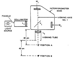
Assembly and Alignment of the It is assumed that the student has already completed Module 10-4, "Michelson Interferometer," and knows how to assemble and align the device using the 25-9093 Ealing Universal interferometer kit. Therefore, this procedure begins with the Ealing interferometer kit in the Michelson configuration with the diffusing screen and lamp in position. After the Michelson interferometer has been adjusted so that circular fringes are visible, the diffusing screen is removed, and the collimator is inserted as shown in Figure 4.
Fig. 4
The collimator is held in a cradle by a spring so that it can be readily removed or replaced. The cradle is attached to the interferometer base with the two bolts and secured. The collimator is positioned in the cradle with the pinhole toward the lamp. It is important that the pinhole coincide with the focal point of lens L1. This can be checked by pointing the collimator at a distant object and examining the pinhole with a magnifier. If the image of the distant object as seen through the magnifier is in focus at the pinhole, then the pinhole coincides with the focal plane of the lens. When this is not the case, the collimator tube must be moved in or out until the image of the distant object is in focus in the plane of the pinhole. The next step in the alignment procedure requires that the beam from the collimator, after reflection from P1, be centered along viewing axis #1. This adjustment is made with the eye at position A, looking towards mirror M1. With mirror M2 covered, the student should see an image of the pinhole reflected from mirror M1. The two screws in the collimator cradle are adjusted until the pinhole image appears in the center of mirror M1. Having accomplished this, the viewing tube (without the aperture pupil) is inserted into the lower socket of the bracket with lens L2 toward the beam splitter, as shown in Figure 4. By uncovering mirror M2 and moving the eye to position B, which is about 40 cm from the end of the viewing tube, the student should see two small images of the pinhole, which are located near the end of the viewing tube. With the two images in sight, the eye is moved closer to the images until both fall onto the pupil of the eye. The student should now see a bright patch of light. In the event the images are too far apart, they can be brought closer together by adjusting the angular orientation of mirror M2. The alignment of the Twyman-Green interferometer is completed by setting the metal cross line, which comes with the interferometer kit, in front of mirror M1 and appropriately adjusting the tilt screws of the collimator until the shadow of the cross line is coincident with the bright patch of light when viewed from a position between A and B as described above. This final adjustment is necessary to assure that the light beams along the two legs of the interferometer are retracing their respective paths. EXPERIMENT 1. Using the Twyman-Green Interferometer to Test an Optical Flat for Polishing Errors. In the grinding and polishing of optical flats, it is important to periodically check one’s progress by measuring the surface flatness of the optical specimen. This is usually accomplished by laying the sample on an optical reference flat and viewing the resulting fringes under a mercury lamp. This test for flatness or polishing inaccuracies can also be performed with a Twyman-Green interferometer provided that the specimen does not have any inhomogeneities in its refractive index. For such a measurement, the Twyman-Green interferometer must first be aligned according to the procedures outlined above. Then the sample with the polishing errors is placed between the beam splitter P1 and mirror M2 as shown in Figure 5. If the sample is too thick, no fringes may be visible. This is due to the fact that the light source is only semi-monochromatic and, therefore, has a short coherence length. It can be shown that fringes are visible only when the difference of the optical paths in the two interferometer legs is less than the coherence length of the light source.
Fig. 5
If the sample has perfectly flat surfaces, the returning wavefront is plane and no fringes are observed. However, if the optical flat is not perfectly flat on both sides, the waves from M2 returning to the beam splitter are no longer plane. Now the phase difference between the superimposed waves will vary across the field of view and a fringe pattern may be seen. These fringes, being lines of equal phase difference, are actually a contour map of the distorted wavefront, so that the imperfections of the sample show up in terms of wavefront aberrations. It is often helpful to know whether the observer fringe pattern is due to an additional optical path length (which would occur if the sample were slightly thicker at the center of the fringe system) or to a shorter optical path length (which would occur if the sample was slightly thinner at the center of the fringe system). To determine this, it is only necessary to press slightly on mirror M2 in a direction which will cause a minute increase in the path length between M2 and P1. The fringes are then observed to move to points that correspond to a relatively smaller optical path. If the rings of fringes move inward toward the center of the fringe system, the sample is slightly thinner in that region, as shown below. On the other hand, if the fringe system opens up, the sample is slightly thicker in that region. The conclusion drawn above can be understood by studying Figure 6, which shows a cross section of a sample that is slightly thinner at point A. The distorted wavefront (which is a surface of constant phase), after propagation through the sample, is labeled W2 and the undistorted wavefront from the reference leg of the interferometer is labeled W1. Assume that the dashed line represents the crest of wave W2, and the full line represents a trough of wave W1. The light intensity will be zero at the point where the two wavefronts intersect, due to the destructive interference effect. This takes place at points B and C in Figure 6. Moving mirror M2 a small distance away from the sample will cause W2 to move back a corresponding distance and points B and C (which correspond to the location of dark fringes) to move toward each other.
Fig. 6
To summarize, by slightly moving mirror M2 and observing the resulting fringe motion, one can determine whether the region is thicker or thinner than the rest of the sample. EXPERIMENT 2: Using the Twyman-Green Interferometer to Observe Index of Refraction Inhomogeneities in a Plane Parallel Glass Plate. It is often necessary to know whether a plane parallel optical component, such as a window, beam splitter, or laser rod, is free from index of refraction inhomogeneities. It is a relatively simple procedure to observe such inhomogeneities with the help of a Twyman-Green interferometer. The experimental procedure for this test is essentially the same as that described in Experiment 1. To ensure that both surfaces are optically flat, the surfaces of the sample should first be tested with an optical flat. To measure the inhomogeneities in the refractive index, the sample is placed between the beam splitter P1 and mirror M2 as shown in Figure 5. The remainder of this experiment is then identical to Experiment 1. Either straight, parallel fringes or a uniformly illuminated field of view is an indication that the sample has a uniform index of refraction. On the other hand, a fringe pattern such as the one in Figure 3b is characteristic of inhomogeneities in the refractive index of the sample. Straight, parallel fringes are an indication that either the sample is wedged or the wavefronts from the mirrors are not perfectly parallel. EXPERIMENT 3: Using the Twyman-Green Interferometer to Test a Prism for Surface and Transmission Errors. This experiment uses the 25-9093 Ealing Universal interferometer kit in the Michelson configuration with the diffusing screen and viewing tube removed and the collimator used in Experiment 2 in place. The prism for which the surface and transmission errors are to be measured should be placed on the small leveling table that comes with the kit. A slightly raised triangular platform on the upper surface of the leveling table indicates the correct location of the prism. The prism is held in place by the spring clip fastened to the vertical threaded pillar. The leveling table with the prism is placed between the beam splitter P1 and mirror M2 so that the bolt protruding from the bottom of the leveling table fits through the attachment hole in the interferometer base. The leveling table is fixed to the base with a coiled spring inserted between the underside of the base and the nut. The nut should be tightened until the spring is under slight compression. The next step involves the alignment of the prism and mirror M2. This is best done by looking into the interferometer in the direction of M1 with the eye approximately 40 cm from the beam splitter. The image of source S can be seen in mirror M1. While still looking in the direction of M1, mirror M2 must be moved slowly along the metal quadrant to approximately the position shown in Figure 7, until colored images of source S via the path P1M2P1 are seen. Because of the difficulty in this alignment, it may happen that the color images are entirely off the field of view. Should this be the case,, some readjustment of the prism table may be necessary.
Fig. 7
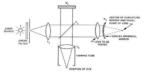
When the prism table is slowly rotated, the student, still looking in the direction of M1, should observe a movement of the colored image of S. The image will stop and begin to move back in the opposite direction when the prism is at the position of minimum deviation for the colored light. It is best to leave the prism at the position of minimum deviation for the green light component and to adjust the screws of M2 until the green image of source S coincides with the image of S as seen in mirror M1. To observe fringes, it is now necessary to insert the viewing tube and put a green filter in front of the light source. Fringes will be seen if the eye is moved up to the end of tube, as was done in previous experiments. The tilt of the fringes can be controlled by adjusting mirror M2. Finally, the visibility of the fringes may be improved by correcting any astigmatism. This is done by inserting the metal cross line in front of mirror M1 and adjusting the screws on the collimator until the shadows of the cross wires exactly coincide. Fringes visibility can also be improved by keeping the optical path length of each leg of the interferometer the same. The less monochromatic the light source, the more important this is. Mirror M1 is fastened to its support with two plastic blocks acting as spacers. These spacers should be removed when using the Twyman-Green interferometer for testing prisms. Once the interference pattern is seen, one marks out the contour lines on the surface of the prism with a magic marker. One then polishes first in the region corresponding to the "highest hill." The polishing is subsequently extended to the next contour line, and so on. At this point, it is important to realize that the fringe pattern observed in this manner may be due to surface errors as well as transmission errors due to local refractive index variations. It is also possible to test the flatness of individual faces of a prism with the Twyman-Green interferometer. From such a test, it is possible to find out if prism errors seen in transmission are due to errors of flatness of the faces or lack of homogeneity of the prism material. To perform this test, the prism table is rotated until reflection is obtained from the face of the prism to be tested. The fringes seen in this manner are very diffuse and difficult to see because the reflected light from the prism surface is now much weaker, and because the optical paths in the two legs of the interferometer are now of different lengths. However, with experience, this test can be performed with acceptable results. EXPERIMENT 4: Use of the Twyman-Green Interferometer to Test Lenses for Aberrations. The Twyman-Green interferometer has been of particular value to the optics industry because of its usefulness in testing lenses for aberrations. When the interferometer is used for this purpose, mirror M2 is removed and replaced by the lens to be tested and a convex mirror. This arrangement is shown in Figure 8. The convex mirror is positioned in such a way that its center of curvature coincides with the focal point of the lens. Under these conditions, a beam of light whose wavefront is a plane perpendicular to the lens axis will be reflected back on its own path by the convex mirror after passage through the lens. If the lens is free from aberrations, the reflected beam of light will once more exhibit a plane wavefront after passage through the lens. If the reflected beam does not have a plane wavefront, an interference pattern is observed. This pattern forms a contour map which indicates the corrections to be applied to the lens to make its performance perfect. Therefore, only a perfect lens would produce a plane wavefront. Of course, in practice, there are allowable tolerances. For instance, we have learned that the images produced by optical systems are, in all practicality, as good as perfect if errors in the lens surfaces do not exceed a quarter of a wavelength.
Fig. 8
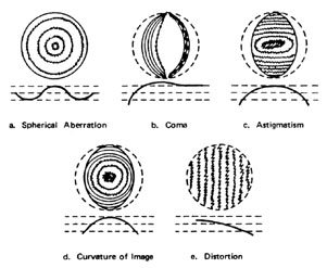
Since the Ealing interferometer kit is not equipped for testing lenses, it becomes necessary to slightly modify and improvise for the purpose of this experiment. The lens to be tested must be mounted in the position shown in Figure 8. The convex mirror is next mounted in such a way that the reflected beam from this mirror, after passing through the lens for the second time, is again collimated. The next step involves the alignment of the convex mirror M2. This can be done by looking into the interferometer in the direction of M1 with the eye about 40 cm from the beam splitter. The image of the source can be seen in mirror M1. By adjusting the angular orientation of mirror M2, the image of the source from M2 must be made to coincide with the image of S as seen in M1. To observe fringes, the viewing tube must be inserted as shown in Figure 8, and a green filter must be placed between the light source and the collimator. Fringes will be seen if the eye is moved up to the end of the tube, as was done in the previous experiments. Some typical fringe patterns and the corresponding wavefronts from both interferometer legs are shown in Figure 9.
Fig. 9
Each fringe pattern typifies a particular lens aberration characterized as follows:

1. Sketch the basic optical system for a Michelson interferometer and a Twyman-Green interferometer. Point out similarities and differences. Indicate how to convert a Michelson interferometer into a Twyman-Green interferometer. 2. Explain, with appropriate drawings, how the Twyman-Green interferometer operates. Include a discussion on how the emerging beams from an interference pattern are viewed by the observer. Include also a discussion of the effect an imperfect optical component (such as one of the mirrors) has on the fringe pattern. 3. List at least four uses of the Twyman-Green interferometer. 4. Sketch the basic optical arrangement used with a Twyman-Green interferometer to accomplish the following:
5. The following figure shows a fringe pattern generated by a lens as it is being inspected with a Twyman-Green interferometer. One side of the lens is perfectly flat.
Fig. 10
6. Continuous wave (CW) operating lasers serve as superior light sources for Twyman-Green interferometers.
Cook, A. H. Interference of Electromagnetic Waves. pp. 72-74. Oxford: Clarendon Press, 1971. Francon, M. Optical Interferometry. pp. 201-202. New York: Academic Press, 1966. Hecht, E. and Zajac, A. Optics. pp. 322-324. New York: Addison-Wesley Publishing Co., 1974. Nussbaum, A. and Phillips, R. A. Contemporary Physics for Scientists and Engineers. Englewood Cliffs, NJ: Prentice Hall, 1976. R & J Beck Limited. Interferometers Instruction Manual. Greycaine Road, Watford WD 2 4PW. Steel, W. H. Interferometry. pp. 109-112. London, New York, Toronto: Longmanns, Green and Co., 1955. Tolansky, S. An Introduction to Interferometry. pp. 109-112. London, New York, Toronto: Longmanns, Green and Co., 1955. Twyman, F. "An Interferometer for Testing Camera Lenses." Phil. Mag., Vol. 42 (1921), pp. 777-793. Twyman, F. Prism and Lens Making. 2nd ed. Chapters 11 and 12. London: Hilger and Watts Ltd., 1952. Twyman, F. "The Holger Microscope Interferometer." Journal of the Optical Society of America. Vol. 7 (1923), pp. 635-656.
|