| This version reflects the comments of the core participants as reviewed and incorporated in accordance with CORD's FIPSE-supported Curriculum Morphing Project. | |||||||||||||
MODULE 10-2 INTRODUCTION In many phases of optical work, it is necessary to obtain the transmittance, reflectance, or absorbance of solids, liquids and gases. Occasionally it may be required to determine the spectral emittance of light-emitting materials as well. Furthermore, it is desirable to obtain the variation in such quantities as a function of the wavelength. Such information allows the engineer or scientist to choose proper filters, antireflection coatings, thin film protective coatings for mirrors, and so on, or conversely, to determine the basic optical properties of dyes and gases that may be used in lasers. Measurement of emitted radiation can allow one to identify the source and its temperatures and concentration (density). Thus, it is necessary to have available an instrument that will provide a calibrated source of nearly monochromatic light at various wavelengths. Such a device is called a monochromator, the name being derived from the two words "mono" meaning one and "chroma" meaning color. In short, a monochromator is a device that selects light in a narrow band of wavelengths from a beam of light in which a range of wavelengths is present. This module is concerned with the basic design of such an optical instrument and its use in obtaining transmission and absorption spectra of optical filters. MODULE PREREQUISITES Before studying this module, the student should have a basic knowledge of the safety precautions to be observed when using ultraviolet radiation sources and electrical equipment. Furthermore, knowledge of the use and care of diffraction gratings and phototubes is required. For a better understanding of this module, it is suggested that the student have completed Module 6–1, "Optical Tables and Benches"; Module 6–2, "Component Supports"; Module 6–3, "Photographic Components and Supplies"; Module 6–4, "Windows and Flats"; Module 6–5, "Mirrors and Etalons"; Module 6–6, "Filters and Beam Splitters"; Module 6–7, "Prisms"; Module 6–8, "Lenses"; Module 6–9, "Gratings"; Module 7–8, "Mechanical and Bleachable Dye Methods"; Module 7-10, "Acousto-Optic Devices"; and Module 8–1, "Welding." 
Upon completion of this module, the student should be able to: 1. Demonstrate a knowledge of monochromators by writing statements explaining the basic components of a monochromator and how it is used to produce a small wavelength band of light. 2. Using suggested equipment, set up a monochromator to view the emerging light from both spectral line sources and broadband sources. 3. Verify the wavelength calibration of a monochromator using a mercury lamp as a source. 4. Investigate the spectral response characteristics of a system containing a tungsten source, a monochromator, and a phototube. 5. Using a monochromator, obtain the transmittance versus wavelength variation for a cutoff filter, a broadband pass filter, and a narrow pass filter. 
In Module 10–1, "Spectrometers," you studied both prism and grating spectrometers. The basic principles used in the spectrometer also are used in the monochromator. In the spectrometer, the various wavelengths emerge at different angles, and a telescope is rotated to observe each wavelength. In the monochromator, on the other hand, internal adjustments allow one to obtain all wavelengths successively at one exit slit. Thus, the monochromator could be thought of as a black box with a wavelength "adjusting knob" and an input and output opening. The light source is placed at the input, the various wavelengths are dispersed in the box, and the wavelength chosen by the "adjusting knob" emerges at the output. The dispersion of the light can be accomplished in several different ways, e.g., by a prism, a reflection grating, or a transmission grating. Although reflection gratings normally are used for this task, we shall consider a monochromator design based upon a transmission grating since this is the design used in the instrument that will be employed in this experiment. A beam of parallel light of wavelength l is incident upon a transmission grating of grating constant "d " at an angle q i as shown in Figure 1. After diffraction, the light will emerge at some angle q d, depending upon the wavelength of the light and the angle of incidence q i. The mathematical relationship between q i, q d, d, and the wavelength l is given by Equation 1. Fig. 1
This equation indicates that various wavelengths can be successively obtained at a fixed exit slit, that is, a fixed angle q d, by simply varying the incident angle q i. This is the technique used in the monochromator employed in the present experiment. This basic design is shown in Figure 2.
Fig. 2
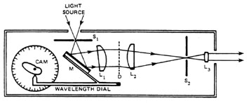
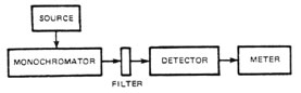
Light from a source is focused through an entrance slit S1 onto mirror M. It is reflected and passes through lens L1, which renders it parallel. Lens L2 focuses the dispersed light from grating D onto the exit slit S2. The lens L3 is present only as an auxiliary lens to collimate the light, after dispersion, into a beam. Variation of q i is produced by rotating the wavelength dial, which in turn rotates a cam, thereby tilting the mirror M. In this way, various wavelengths (one at a time) can be obtained at exit slit S2. This is the basic design used in the Welch Chem-Anal monochromator employed in this experiment. The important characteristics of a monochromator are the wavelength range over which it can be used and the bandwidth of the emerging light. The wavelength range is determined by the properties of the optical components and the angle over which the mirror can be rotated. In the case of the Chem-Anal unit, this range is 350 nm to 650 nm. However, monochromators that cover various wavelength ranges between 50 nm and several microns are commercially available. The bandwidth is determined by the dispersion of the grating (see Module 10–1, "Spectrometers") and the width of both the entrance and exit slits. In the case of the Chem-Anal unit, this bandwidth is fixed at 200 Å or 20 nm. Thus, two spectral lines that are less than 20 nm apart pass through the exit slit at the same time and cannot be resolved. In this way, the bandwidth determines the monochromaticity of the emerging light. A monochromator has two basic uses: (1) as a wavelength analyzer for an unknown source of light or (2) as a wavelength source. A wavelength analyzer is required if one needs to know the spectral distribution available from a light source such as a sodium lamp, a mercury lamp, a tungsten filament, or a laser. A monochromatic light source is required if one wishes to determine the transmittance, absorbance, or reflectance of a filter or antireflection coating as a function of wavelength. When used as a wavelength analyzer, the monochromator is placed as shown in Figure 3. The light source is focused onto the entrance slit of the monochromator and the intensity of the light emerging from the monochromator is measured at each wavelength by a detector. Detectors that are used include thermopiles, radiometers, photomultipliers, photodiodes, and phototubes.
Fig. 3
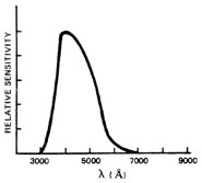
A problem that arises in the use of this type of instrument is that the detector is often not equally sensitive to all wavelengths. For example, the sensitivity of an RCA 934 phototube is shown in Figure 4. As can be seen, this tube is not sensitive to optical radiation below 3000 Å (due to the total absorption of ultraviolet light by the glass envelope of the phototube) nor is it sensitive above 6500 Å (due to the nature of the photocathode surface). Between these limits, there is great variation in the sensitivity of the tube with wavelength. Thus, if one examined a light source that was equally intense at all wavelengths, the spectrum obtained would appear as that shown in Figure 4 as a result of variation in tube sensitivity. To obtain a proper spectral distribution of the source, one could use a detector that has a "flat" response, i.e., equal sensitivity at all wavelengths of interest. Thermopiles and photometers are "flat" in response and should be used for measurements where possible; however, their overall sensitivity is considerably less than that of a phototube. If a phototube must be used, its response curve (Figure 4) must be known and appropriate correction made.
Fig. 4
When the monochromator is used as a monochromatic light source, the arrangement shown in Figure 5 is used. In this case, it would be desirable to have a source of light that emits a broadband spectrum with equal intensity at all wavelengths. Such a source is not available. As a result, one either must know the precise source spectrum or must provide for some mechanical or electrical method of correcting for the variation in source spectrum. Since a tungsten filament source is used in the Chem-Anal system and since this source is not "flat," such a correction system will be introduced in this experiment.
Fig. 5
In measuring the transmittance of an optical filter, the arrangement shown in Figure 6 is used. In this measurement, even though several types of sources could be used, a tungsten filament source will be chosen. The detector that will be used is the RCA 934 vacuum phototube. Neither source nor detector has a flat response, and corrections will have to be applied. The output of the detector is amplified and measured by a meter. To correct for the source spectrum and detector response, one proceeds as follows: 1. With no filter in the beam path, the desired wavelength on the monochromator is chosen and the amplifier gain is adjusted for a full scale reading. 2. The filter is placed in the beam path and transmittance is read on the meter.
Fig. 6
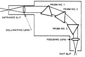
This procedure is repeated for all wavelengths of interest. In this way, the gain of the amplifier circuit is adjusted at each wavelength to overcome the variations introduced by the tungsten source and the phototube. As a result, one can obtain a plot of transmittance as a function of wavelength which is a true representation of the filter. Before we begin using the Welch Chem-Anal monochromator for some measurements, it should be noted that there are many different monochromator designs from which to choose. For instance, some monochromators are built around several prisms. One such device is shown in Figure 7. In this instrument, the collimator and focusing lens have a fixed deviation of 90° . The prism table and prisms are rotated by a micrometer screw so that any desired wavelength can be brought to the exit slit. The micrometer screw also drives a scale from which the wavelength of the light passing through the exit slit is read.
Fig. 7
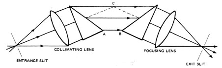
A versatile monochromator using a Young-Thollon half-prism arrangement is shown in Figure 8. In Figure 8, the symmetrical path of a ray at minimum deviation is shown. If one prism (say A) and its associated collimator lens are fixed, while the other prism and lens rotate together about an axis at C, the ray at minimum deviation will always pass through the system symmetrically.
Fig. 8
The same effect can be achieved if the two prism points, A and B, are in contact and this common point is used as the axis of rotation. This design has constant deviation and, as the prisms are rotated in opposite directions, any desired wavelength can be brought to the exit slit. For the UV region, the instrument is equipped with quartz prisms and quartz-lithium fluoride lenses. To improve image quality, either achromatic doublets or apochromatic triplet lenses must be used. One advantage of the half-prism arrangement is that, with lenses of a given diameter, the use of this arrangement permits the use of smaller prisms which have less refractive index in homogeneity than larger prisms. On the other hand, there will be some loss of resolving power, since this depends upon the thickness of the prism base. In addition to the monochromators described above, there are still other designs. Some use concave mirrors instead of collimating and focusing lenses. Some of these may offer greater purity of the emergent light, but they are otherwise identical in principle. In summary, a monochromator is an instrument used to supply a beam of light having some desired, narrow range of wavelengths. The common form resembles a prism or grating spectroscope. In general, white light enters the fixed collimator through a narrow slit and is dispersed by a suitably-shaped prism or grating. The resulting spectrum falls on a metal plate, and a second narrow slit allows "monochromatic" light (actually light of a narrow range of wavelengths) to emerge. The monochromator is particularly useful (with proper choice of optical materials) for radiation outside of the visual range, where the detector is some type of phototube, thermocouple, or photoconductive detector.

1. Without looking at Figure 2, prepare a schematic drawing of the internal design of the monochromator described in this module. 2. Explain the basic components of a monochromator including such items as transmission grating and lenses. 3. Explain how the monochromator is used to produce a small-wavelength band of light. 4. Explain the procedure used to verify the wavelength calibration of a monochromator. 5. Identify the three monochromator components that affect the bandwidth of the light emerging from the exit slit, and explain what could be done to minimize the bandwidth. 6. One of the objectives of monochromator designers is to eliminate stray light. Explain why this is important and suggest some ways in which stray light can be minimized. 7. Refer to Figure 1. If q d = 15° and the grating has 1200 lines/mm, calculate the range of values of q i so that the monochromator can be used over the visible range (4000 Å – 7000 Å). Assume that the grating will be used in first order.

Welch Chem-Anal system (tungsten source, monochromator, detector, meter, optical mount, and power supply) Mercury light source Lens (5-cm focal length) Optical filter (Corning #5543) Optical filter (Corning #3385) Optical filter (Optics Technology #370, or equivalent narrow band filter)

Before beginning the experiment, consider safety procedures, particularly those relevant to ultraviolet radiation. In this module, the student will perform three experiments: 1. Set up the monochromator and check its calibration using a mercury lamp. 2. Determine the spectral response of the system using a tungsten lamp. 3. Determine the transmittance of a cutoff filter, a broadband pass filter, and a narrowband pass filter. Since the heart of this experiment is the Welch Chem-Anal system, the student should read Pages 5 through 9 of the Chem-Anal manual before beginning.
Set-Up and Calibration 1. Fasten the monochromator to the optical base. The monochromator has a hinged lid that may be raised to show all functioning parts. A hard plastic cover is located immediately below this lid to protect the internal components. This plastic cover should not be removed unless wavelength calibration is required. Study the arrangement of the components and compare the optical system with Figure 2 and the accompanying discussion. 2. Focus the light from the mercury lamp onto the entrance slit of the monochromator using the 5-cm focal length lens. Make sure that as much light as possible enters the slit. Observe the path of the light through the plastic cover as it traverses the optical components of the monochromator. Observe the mercury spectrum that can be seen on the exit slit holder and how that spectrum moves as the wavelength dial is rotated. 3. Hold a white card near the exit opening of the monochromator. Rotate the wavelength dial and observe the various mercury wavelengths on the card. Record the wavelength setting and the color of the output light for each of the lines in the mercury spectrum. Compare these values with those given in Figure 9, where all lines are in angstrom units.
Fig. 9
4. If your values do not agree with those in Figure 9, the monochromator is out of calibration and must be adjusted. In comparing values, remember that the bandwidth of the monochromator is 20 nm. Thus, there will be considerable random variation in your values. If adjustment is necessary, refer to the Chem-Anal manual, Section III-A-2, Page 14. 5. At this point, the monochromator should be in adjustment and you should have some understanding of its design and operation, as well as the type of spectrum one obtains from a spectral line source.
System Response to a Tungsten Lamp 1. Attach the tungsten light source to the monochromator. This source consists of a tungsten lamp, a lamp adjusting screw, and a lens. The lamp adjusting screw moves the lamp horizontally for optimum positioning of the output beam, and the lens focuses onto the entrance slit. Observe the light beam in the monochromator. Adjust the position of the lamp until the focused light beam is centered on the entrance slit. Observe the spectrum of the tungsten lamp on the exit slit. Note that this is a continuous spectrum. Rotate the wavelength dial and observe the light from the monochromator on a white card. Note that, since the dispersion of the grating is low and the exit slit is quite wide, the emerging light is not strictly monochromatic. 2. Mount the detector and meter on the optical base with a 1-inch space between the monochromator and the detector. The detector is an RCA 934 phototube that has a S4 response. Do not apply any power to the detector at this point. Open the lid of the detgctor module and observe the tube. The electronic circuit that you see is the amplifier circuit. The lid contains three controls: one marked blank, one zero, and one reference. The blank control is not used; set it to a maximum clockwise position. The zero control is used to set the instrument response to 0.0 on the meter for no light incident, i.e., with the light path blocked. The reference control is used to adjust the gain of the amplifier circuit. The limit of rotation of the control is indicated by an increase in friction. 3. Connect the detector to the power supply and the meter to the detector (see Figure 10). Close the lid of the detector module and keep it closed at all times when power is on.
Fig. 10
Turn on the power supply and allow 10 minutes for the circuit and lamp to stabilize. Keep room lights off since, in this configuration, room light can enter the detector. 4. Cover the entrance to the detector to exclude all light. Use the zero adjust control to set the meter to 0.0 on the transmission scale. Uncover the detector entrance and rotate the wavelength dial to find the wavelength at which the maximum meter deflection occurs. At this wavelength, set the meter to read 100 on the transmission scale (use the reference control for this adjustment). Turn the wavelength dial to 350 nm (3500 Å) and record the meter reading. Vary the wavelength in 10-nm intervals from 350 to 650 nm and record the meter readings at each point. Plot meter reading versus wavelength. This curve represents the combined effect of the tungsten lamp, the monochromator, and the detector.
Transmittance of a Filter To obtain the transmittance at a selected wavelength, one follows the procedure below: 1. Set wavelength. 2. Block light path and set 0.0 with zero adjust. 3. Unblock light path and set 100.0 with reference control. 4. Place filter in light path and record % transmittance from meter. This procedure is repeated for each wavelength of interest. Perform this measurement on the following filters:
These measurements should be made every 10 nm over a wavelength range of 350 nm to 650 nm. A plot should then be made for each transmittance curve. Compare your results with those published by Corning and Optics Technology.

Meltzer, R.J. and Kingslake, R., ed. "Spectrographs and Monochromators." Applied Optics and Optical Engineering. Volume V, Chapter 3. New York: Academic Press, 1969. Sawyer, R.A. Experimental Spectroscopy. 3rd ed. New York: Dover Publications, Inc., 1963. Zimmerman, J. and Haenisk, E. Welch Chem-Anal Manual. Sargent-Welch Scientific Co., (Catalog #4883M). Further information on monochromators may also be obtained from the following companies:
--------------------------------------------------------------
|
|||||||||||||