|
MODULE 6-5 MIRRORS AND ETALONS © Copyright 1987 by The Center for Occupational Research and Development All rights reserved. No part of this book may be reproduced in any form or by any means without permission in writing from the publisher. The Center for Occupational Research and Development 601 C Lake Air Drive ISBN 1-55502-024-0 (1) A mirror is a smooth surface that can reflect enough light to serve a useful purpose. Mirrors have been used since man first saw his image in a calm pool of water. They have progressed from the great silver-blackened hall mirrors of the eighteenth century to where, today, they are used to reflect light within a laser cavity. (2) This module will instruct you about the recognition and specifications of various mirror types, their limitations and their applications. (3) Before you begin this module, you should have studied optical cavities and modes of oscillation, light rays, reflection of light, reflection of light at a plane boundary, and reflection of light at a spherical surface.
(4) When you complete this module, you should be able to do the following:
DISCUSSION (5) When light strikes the surface of any object, some of the light is reflected, some is absorbed by the object, and some is transmitted through the object. The extent to which each of these processes occurs varies. Some objects transmit the major portion of the incident light, some objects absorb most of the incident light, and other objects reflect most of the incident light. Objects designed to reflect most of the light are called "mirrors." (6) The amount of light reflected by a mirror depends on:
(7) We will discuss some of these factors in more detail in this module. (8) The reflection from the surface of a high-quality mirror is called "specular." This means that the rays striking the surface are reflected from the surface according to the law of reflection, qi = qr. Figure 1 shows specular reflection from a polished mirror surface. Fig. 1 (9) Not all reflectors, however, are specular reflectors. Some are diffuse reflectors, which means that the rays are reflected in random directions. Figure 2 shows diffuse reflection. Common examples of diffuse reflection include the reflections from this paper and from projection screens. Fig. 2 (10) Figure 3 illustrates a plane mirror used to form a virtual image by reflection. The virtual image formed by a plane mirror corresponds in size and shape to the object and is the same distance behind the mirror as the object is in front of the mirror. The image is correctly oriented from top to bottom, but the right and left parts are interchanged. Fig. 3 (11) To illustrate this point further, let’s consider Figure 4. If the word READ is considered to be right-handed and is readable, then the mirror image of the word must be considered to be left-handed. It has been turned left for right. No matter how the word is turned, it will remain left-handed. To read it correctly, you must either use a second mirror to turn it or turn the paper over and look at it from the other side. The image from a single surface reflection is always left-to-right inverted
Fig. 4 (12) As you learned from an earlier module, curved mirrors form either
real or virtual images by converging or diverging light. Inexpensive,
curved, spherically convex mirrors which diverge
incident rays can be used to enlarge a field of view. Such an
application is the small "spot" mirror attached to the rear
view mirror of an automobile. Low-quality spherically
concave mirrors which converge incident light rays (13) The quality, size and reflectivity of mirrors largely determine their use. For instance, the searchlight shown in Figure 5 does not require a high-quality mirror since a focused image is not being formed by the system. (14) The reflecting telescopes shown in Figure 6 require mirrors of very high optical quality to produce usable images. The reflectivity of the telescope mirrors doesn’t have to be extremely high since a reasonable amount of light absorption in the system can be tolerated. (15) Mirrors used for the end reflectors in laser cavities must be of high optical quality and have high reflectivity. Even small absorption or scattering losses in this application may render the system inoperable. Fig. 5
Fig. 6
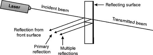
Mirror Limitations (16) Mirrors used as imaging systems suffer from many of the same defects as lenses. These defects include spherical aberration, coma, astigmatism, curvature of field, and distortion. You can find a more complete description of these defects in a lesson on lenses. (17) Rays of light striking the outer portions of a spherical reflecting surface don’t focus at the same point as rays striking the center portion of the surface. This is known as spherical aberration. It will cause an out-of-focus image. Short-focal-length mirrors are plagued by spherical aberration more than are longer-focal-length mirrors. This is because the short-focal-length mirror has a much sharper curvature. (18) Spherical aberration can be controlled or eliminated in several ways. If the aperture of the mirror is limited, the outside rays of light will not strike the reflecting surface. This prevents them from causing the out-of-focus image. This is normally the least expensive way to reduce spherical aberration. (19) A more costly method is also the more perfect method. It consists of using a parabolic shape for the reflecting surface instead of the spherical shape. To understand the reason for using a parabolic shaped reflecting surface, refer to a good analytic geometry textbook. (20) Note that, when it’s used off-axis a spherical mirror may produce a better image than a comparable parabolic mirror. Parabolic mirrors usually are used in optical systems, such as telescopes, where the incident rays are nearly parallel to the mirror’s axis of symmetry. (21) A third way to minimize spherical aberration is a technique developed by Bernhardt Schmidt, the so-called "Schmidt telescope" or "Schmidt camera." In this optical system, a thin transparent "correcting plate" is placed at the center of curvature of the spherical mirror. (See Figure 6d.) The plate is essentially a specially shaped lens that corrects the spherical aberration, astigmatism and coma of the telescope’s primary mirror. Schmidt telescopes are popular for applications such as small astronomical instruments where it’s sometimes more cost-effective to fabricate a spherical mirror plus a correcting plate rather than a parabolic primary mirror. (22) Astigmatism is a tendency for a mirror to focus light entering the surface vertical, with respect to a particular axis, at a different point from light entering horizontal with respect to the same axis. This defect causes images of a point to be extended into a line. All optical elements display some degree of astigmatism although it can be greatly reduced by appropriate combinations of lens and/or mirror elements. (23) Because the quality of a mirror depends on the rigidity of the substrate material, it’s usually made of some stiff material like glass. In less stringent applications plastic may suffice and in more severe applications, materials more rigid than glass may be necessary. The substrate material must be thick enough to minimize distortion of the mirror surface. It is also advisable to mount the mirror on three support points only, to avoid stress-induced distortion. (24) When glass is used as the mirror substrate, reflection from an uncoated front surface generally will produce a "ghost image." The "ghost image" is slightly displaced from the main image that arises from the highly reflective rear surface. For this reason most high-quality mirrors are made with front or first reflecting surfaces on top of the glass substrate. (25) Many optical systems can operate very well even with low-quality mirrors. Other systems require one or all the defects to be minimized. A mirror of too low quality may hinder the operation of your equipment or decrease its accuracy. Too good a mirror may represent a needless expense. As discussed later, mirror quality must be related to its application.
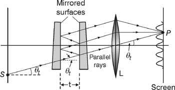
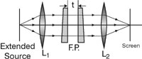
Reflecting Surfaces (26) To obtain high specular reflectance, the polished glass or plastic surface can be coated with a metallic layer. Silver was the classical material used for this purpose. A highly polished silver surface reflects ~ 95% of the incident light in the visible range. Silver, however, has to be protected from tarnishing. So it has been largely replaced by aluminum evaporated onto the polished substrate in a high vacuum. On contact with the atmosphere, a thin layer of aluminum oxide forms on the surface of the aluminum film and provides some protection. Other protective coatings or "overcoats" often are needed. These will be mentioned later. (27) The reflectance of metals depends on the wavelength, the surface preparation, the angle of incidence, and specific properties of the metal itself. Figure 7 shows the variation of the reflectance of a number of typical metals as a function of visible wavelength. (28) Silver and aluminum are of particular importance for general use because they maintain their high reflectance throughout the visible spectrum. It’s now standard practice to coat the mirrors of large telescopes, such as the 200-inch Hale reflecting instrument at Mt. Palomar, with evaporated aluminum. For reflecting surfaces where the small advantage of silver over aluminum is important, as in Fabry-Perot etalons, silver is preferred. For use with visible and infrared light, silver is also preferred. But for ultraviolet light aluminum is better, and gold may be preferred at longer wavelengths. Fig. 7 (29) As was mentioned earlier, some metals (aluminum) form their own protective layer. This layer is very thin, however, and it is usually advisable to provide additional protective coatings. Silicon monoxide frequently is used for this purpose. It causes some reduction in reflectance, but this reduction is less than is experienced by aging processes. Magnesium fluoride also can be used as a protective coating. The effect of these two coatings on the reflectance of aluminum is shown in Figure 8. Fig. 8 (30) You should note from Figure 8 that different protective coatings affect the reflectivity differently as a function of wavelength. For example, if you needed a mirror for reflecting light of 2-micrometers wavelength, silicon monoxide would be best. If 10 micrometers were the area of interest, magnesium fluoride would be the better choice. (31) In some applications that involve multiple reflections—such as a laser cavity—even the high reflectance of the metals shown in Figure 7 may not be enough. Surfaces that have a higher reflectance than any metal can be produced. These surfaces generally are composed of several dielectric materials and use the principle of interference to produce high reflectance values. (32) The dielectric or multilayer film mirrors sometimes are combined with a metal mirror to improve the reflectance. Figure 9 shows the reflection enhancement of a metal mirror due to rnultilayer coatings. The dielectric materials in Figure 9 are zinc sulfide and cryolite, both vacuum deposited on a metal mirror to a highly controlled thickness. Fig. 9 (33) Notice that reflectances very near to 100% can be achieved by this method. The high reflectance does not, however, extend over as great a wavelength range as does that of bare metals. The reflectance of a dielectric or dielectric coated metal is peaked very strongly around a particular wavelength of light. The reason for this should become apparent in the following discussion. (34) Consider Figure 10. The incident light is divided into two different beams by a partially reflecting surface. Each of these beams travels a different distance and interference is observed when these two rays recombine. As shown in Figure 10 the light from the source impinges upon surface S1. Part of this beam is reflected at a point A. The remainder penetrates the medium between the two surfaces S1 and S2 and reflects back and forth between them. The thickness of the dielectric is h1, and q1 is the angle of incidence in the medium of index of refraction n1. Fig. 10 (35) If the reflectance of the surfaces is low, the beam may reflect only once before it’s greatly attenuated. If the reflectance is close to unity, it may reflect as many as 30 times. In either case, the beams that reflect from either side of the film have traveled different optical paths and interference is observed when they recombine. (36) If several dielectric films—each a quarter wave thick and with alternately high and low index of refraction—are stacked, the reflected beams from all the interfaces are in phase upon leaving the uppermost boundary. This situation is shown in Figure 11. Fig. 11 (37) Note that light may reflect many times before returning to the upper surface. But when it does this, it’s in phase and going the same direction as all the other reflected light rays. Modern coating technology produces reflectances in excess of 99.999% using approximately 20 layers in a dielectric "stack." (38) You can see in Figure 12 that the reflectance of a dielectric mirror is a strong function of the wavelength of the incident light. The angle of incidence, as well as the specific properties and construction of the dielectric coating are also important mirror parameters. If either of these parameters changes, the light may not travel the right distance through the coating to be in phase at the upper boundary. Fig. 12 (39) Figure 12 shows the reflectance of a three-layer dielectric mirror as a function of wavelength. The curve would be even narrower and the peak higher if more dielectric layers were used. (40) Multilayer dielectric mirrors have been devised for use in the ultraviolet (220 nm) to the infrared (20 mm). A difficulty met in the ultraviolet is that most high-index materials, such as zinc sulfide and titanium dioxide, are absorbing. So you must use materials with a lower refractive index. Antimony trioxide and lead fluoride are good examples of low-refractive-index materials. (41) Laser end reflectors are very common examples of multilayer dielectric mirrors. When you specify such reflectors you must consider a number of items. The mirror must be chosen for use at the desired wavelength. Diameter and thickness must be chosen to coordinate with the size of the mirror mounts to be used. The curvature of both surfaces of the mirror must be specified to match the type of laser cavity and the cavity length. The reflectivity, scattering and absorption at the particular wavelength being used must be a major consideration. (42) Substrate material and surface quality also must be specified. Manufacturers specify surface quality as being flat to a fraction of a wavelength. This flatness is determined by observing the interference pattern produced when the surface is compared to a "perfect" master flat. (43) The flatness of a mirror (or other optical components such as a window’s) surface should be matched to the intended application. For example, wave-front distortion can usually be tolerated in laser material-processing applications such as heat treating and welding. The beam-steering optics in such systems can be of relatively poor flatness—1/4 l should suffice. (44) On the other hand, in many laser applications wave-front distortion must be minimized. As an example, the optics in holographic systems should be of high surface quality to preserve the phase information. Surface flatness of 1/20 l is often desirable. Similarly, the plane cavity mirror and Brewster windows used in many lasers usually are specified to at least 1/10 l flatness to ensure good output beam quality. (45) Note that, unless otherwise specified, optical flatness is measured with respect to the two yellow Sodium D lines (5890 Å and 5896 Å) that historically have been used as a convenient standard (almost) monochromatic light source for optical measurements. (46) A more complete discussion of flatness specifications is given in Module 6-4, "Windows and Flats." (47) Durability of the surface coating usually is specified rather vaguely. But you should consider it when a laser and reflector are to be chosen. (48) One application of multilayer mirrors of particular importance is heat control in projection systems. In most projection systems, a mirror is placed behind the projection lamp to direct the maximum amount of light toward the film. Formerly these mirrors were coated with silver, but this reflected the infrared heat as well as the visible light toward the film. This problem is solved if you use a "cold" mirror instead of the silver. The cold mirror is a multilayer coating that has a high reflectance in the visible spectral region and a high transmission in the near infrared. As shown in Figure 13, this allows the infrared to pass through the rear of the lamp housing. Fig. 13 (49) The performance of such a system is increased even more if a heat reflector is inserted between the lamp and the film. The heat reflector is a mirror in the infrared and a high transmission window in the visible. This reflects even more of the heat from the film. In practice this combination of mirrors can result in a two-to-three times reduction in heat incident on the film. A similar arrangement could be used to pump a laser cavity at the desired wavelength and keep heat-loading to a minimum. Fabry-Perot Etalon (49a) A Fabry-Perot etalon inserted in a laser cavity makes use of mirrored surfaces arranged in a particular geometry to achieve a narrowing of the wavelength spread of the emitted laser light. A Fabry-Perot etalon is nothing more than a Fabry-Perot interferometer with a fixed distance between the two mirrors found in the interferometer. To understand the operation of an etalon, we need first to see just how a Fabry-Perot interferometer works to favor one wavelength over another. Fabry-Perot Interferometer (49b) A typical arrangement for a Fabry-Perot (FP) interferometer is shown schematically in Figure 14. Two thick glass plates are used to enclose a plane parallel section of air of thickness t between
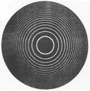
Fig. 14 them. The important surfaces on the glass plates are the inner ones, between which light is multiply reflected, as shown. The mirror surfaces are generally polished to a flatness of l/50 and coated with a highly reflective layer of silver or aluminum. Silver films—around 50 nm thick—are generally used when visible light passes through the FP interferometer; aluminum is used for UV light (below 400 nm) since reflectivity of silver drops off sharply below 400 nm. The outer surfaces of each glass plate are “tilted” at a slight angle relative to the inner surfaces (several minutes of arc) as shown. This is done to eliminate spurious interference patterns that would otherwise arise from reflected beams occurring between the parallel surfaces of the glass plates themselves. (49c) As drawn in Figure 14, if a ray of monochromatic (single wavelength) light from point S passes through the first glass plate, it then undergoes multiple reflections between the two inner mirror surfaces. Since the reflectivity of the two mirrors is not 100%, some of the reflected light at the second surface passes through the second plate and is focused by converging lens L on the screen at point P. If the spacing t between the plates satisfies the condition t cos q = m(l/2) for an incident angle qt, the spot at P is bright. If not, it is dark. As qt changes the condition for interference changes, giving rise to the bright and dark fringes show on the screen. (49d) If an extended source—rather than a point source—is used, and the plate spacing t is kept fixed, the arrangement shown in Figure 15 gives rise to a pattern of concentric fringes—as shown. In this arrangement, collimating lenses L1 and L2, located before and after the two plates, are used to produce the fringe pattern on the screen.
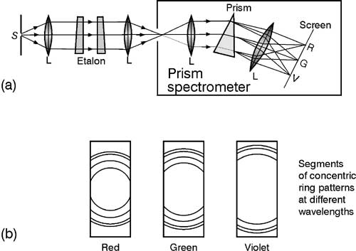
Fig. 15 (49e) Figure 16 shows a Fabry-Perot etalon (mirror spacing t is fixed) in tandem with a prism spectrometer. In this arrangement the prism spectrometer separates the concentric ring patterns formed for the different wavelengths of light, producing patterns for red, green, and violet light, for example, as shown:
Fig. 16
|