| This version reflects the comments of the core participants as reviewed and incorporated in accordance with CORD's FIPSE-supported Curriculum Morphing Project. | |||||||||||||||||||||||||||||||||||||||||||||||||
MODULE 4-4 (1) This module will introduce the student to the basic mechanical, optical, and electrical operation and concepts of flashlamps. Pulsed xenon and krypton flashlamps are used to convert electrical energy to optical radiation for pumping solid-state lasers and some dye lasers. Flashlamps are gas-discharge devices designed to produce pulsed radiation, unlike arc lamps, which are gas-discharge devices designed to produce continuous radiation. (2) The flashlamp is electrically pulsed to produce high values of radiation flux in a given spectral band. The type of flashlamp selected should be able to supply the maximum spectral output in the absorption bands of the laser material. Flashlamp specifications include lamp type and construction, arc length, bore diameter, gas-fill pressure, energy-handling capabilities, lifetime, and cooling requirements. (3) Flashlamps are described electrically as having infinite initial resistance and negative dynamic resistance (impedance). A flashlamp power supply usually consists of a high-voltage DC charging supply, an energy-storage capacitor bank, a pulse-forming network (PFN), and a trigger circuit. Four types of trigger circuits will be described. The design of the pulse-forming networks will also be covered. (4) The module will describe flashlamp characteristics including lamp construction, electrical performance, optical radiation spectra, cooling, degradation mechanisms, lifetime, handling, maintenance, and safety considerations. 
When you complete this unit, you will be able to: 1. Explain why xenon is usually the preferred fill gas for flashlamps. Explain when krypton should be used. 2. Describe the emission spectra of xenon and krypton flashlamps for both low and high values of electrical loading. 3. Describe basic flashlamp operation. 4. Describe two different types of electrode-lamp seals and discuss their relative performance. 5. Explain why fused silica (fused quartz) is usually used as the flashlamp envelope material. 6. Describe four basic types of flashlamp trigger circuits. 7. Explain the simmer and pseudosimmer modes of flashlamp operation and discuss when they would be used. 8. Describe the process of selection of a flashlamp for a given application. 9. Sketch the flashlamp current as a function of time for underdamped, overdamped, and critically damped operation. Explain problems associated with underdamped and overdamped operation. 10. Describe how use of a multiple-mesh pulse-forming network changes the pulse shape as compared to a single-mesh network. 11. Explain proper maintenance and care of flashlamps. 12. Describe potential hazards associated with flashlamp operation and discuss methods to minimize them. 13. Calculate expected flashlamp lifetime, given the explosion energy and the pulse energy. 14. Given the desired input energy, pulse duration, and flashlamp parameters, design a single-mesh circuit for pulsing a flashlamp with a critically damped discharge and determine appropriate values for capacitance, inductance, and charging voltage. 15. Using equipment provided in the laboratory, design and construct a pulse-forming network to drive a flashlamp that pumps an Nd:YAG laser. Measure the parameters of the current pulse and the laser pulse as the values of the circuit components are varied. Operate the pulse-forming network as a single-mesh network and as a multiple-mesh network and compare the outputs in the two cases.  Introduction to Flashlamps
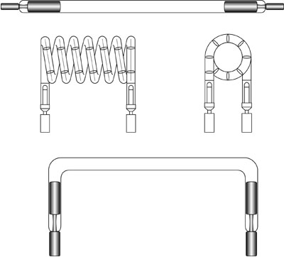
(5) Flashlamps are pulsed sources of light. They are in the form of linear or helical quartz envelopes with circular cross section. They are filled with gas (usually a noble gas, xenon or krypton) and have two electrodes sealed into the envelope. An electrical discharge between the electrodes is initiated by the power supply and very large pulsed electrical currents flow through the gas. During this pulsed current flow, intense optical radiation is emitted. Flashlamps are widely used for pumping pulsed solid-state lasers. They have also been used for photography and for applications such as studying phosphorescence and for initiating and monitoring the progress of chemical reactions. (6) Figure 1 shows some typical lamp configurations. Linear flashlamps are in the form of straight tubes, with bore diameter of from 3 to 19 millimeters and a wall thickness of 1 to 2 millimeters. Lengths in the 5- to 10-centimeter region are common, but lamps as long as one meter are available.
Fig. 1 (7) Helical flashlamps offer longer arc lengths and larger wall areas, and hence can deliver higher pulse energy for a laser rod of a given length. They have bore diameters and wall thicknesses similar to the linear flashlamps. They have been used for pumping high-energy ruby lasers. Views of helical lamps are shown in the middle portion of the figure. (8) A U-shaped lamp is basically a linear lamp with the ends bent to form a U shape as shown in the lower portion of the figure. This configuration allows the electrical contacts to the end of the lamp to be made conveniently at some distance from the laser rod, which is adjacent to the long portion of the lamp. U-shaped flashlamps have been used in the past, but seem to be little used in modern solid-state lasers. (9) The lamp is filled to a pressure usually in the range of 300 to 700 torr. The fill gas is most often xenon. Xenon produces higher total radiative output for a given electrical input than do other gases. In some applications, the radiative emission from krypton is a better match to the laser material’s absorption spectrum. In particular, it offers a better match to the absorption spectrum of Nd:YAG and is often used as the fill gas in flashlamps used to pump Nd:YAG lasers. The characteristics of the emission spectra from xenon and krypton will be discussed in detail later. (10) Two variant types of flashlamps are available, a short-arc type and a nanosecond pulse-duration type. Neither of these is used for pumping lasers, but they have applications in areas such as fluoroscopy, flash photolysis, machine vision, and phototypesetting. This short-arc type, with arc lengths of around 3 millimeters, offers a compact, high-intensity source. The nanosecond type offers pulse durations in the 10-nanosecond region. Both types are available with a variety of gas fills, according to the spectrum of the light desired.
Electrical Characteristics of Flashlamps (11) All electrical discharges in gaseous media, including flashlamps and arc lamps, have common characteristics, which were described in connection with Figure 1 of Module 4-2. For completeness here, we shall briefly summarize that discussion. At low values of voltage applied to the gas, there is no current flow. As the voltage is increased, the current remains essentially zero until some relatively high voltage is reached, at which point a very small current begins to flow because of a small amount of ionization that is always present. This current increases slowly until a point called the breakdown voltage is reached. This is the value at which a large number of gas molecules becomes ionized. The conductivity of the gas is increased and the electrons are accelerated to velocities at which they can ionize more molecules through collisions. Thus, as the current increases, the resistance of the gas decreases and the voltage required to sustain the discharge actually decreases with increasing current. This is a condition called negative resistance. (12) The impedance characteristics of a flashlamp determine the energy-transfer efficiency from the capacitor bank to the lamp. The impedance is a function of time and current density. Flashlamp electrical characteristics can be discussed in three distinct areas of operation, which occur sequentially as the electrical discharge through the lamp develops. (13) The electrical characteristics of flashlamps are characterized by these three different operating regimes:
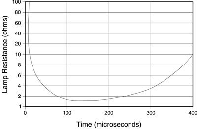
Triggering (14) Triggering is the initiation of an electrical discharge in the gas contained in the flashlamp. The triggering begins with a spark streamer that crosses the gap between the electrodes and creates a conductive path between them. The voltage drop across this path should be less than the voltage supplied by the external circuit, so current will begin to flow through the lamp. (15) Triggering must be reliable and repeatable. The triggering system initiates the arc as a thin streamer of current flow between the electrodes. Unconfined Discharge (16) After the flashlamp is triggered, a relatively low value of current is flowing through the gas. The resistance of the gas is still relatively high, and the electrical discharge is undergoing expansion. The discharge in this regime is still a streamer, not filling the lamp, and is said to be unconfined. The discharge region then begins to expand. As the power supply drives the lamp through this regime, the current increases and the resistance of the lamp drops. (17) The streamer grows in diameter until it fills the tube. The expansion time is fast, usually taking 5 to 50 microseconds. The time for the expansion depends on the amount of charge available from the power supply. In the region of unconfined expansion, the presence of the walls of the envelope exerts little or no influence on the characteristics of the discharge. (18) During this phase, the lamp resistance decreases rapidly as a function of time, as Figure 2 illustrates. The rapid decrease in resistance arises from the increasing ionization of the gas and the radial expansion of the plasma.
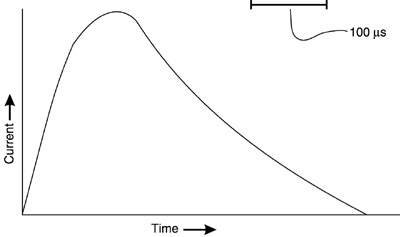
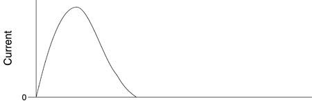
Fig. 2 Wall-Stabilized Plasma Regime (19) This is the most important regime, since it encompasses most of the duration of the pulse and covers the period when most of the light is emitted. (20) This regime is characterized by high values of current flow. It is encountered only in pulsed operation because of the high current density. In Module 4-5 we will discuss a wall-stabilized regime for continuous-arc lamps. The values of current in that case are much lower. (21) In this regime of flashlamp operation, the plasma has expanded to fill the tube, or may still be expanding, but at a rate influenced by its distance from the wall. The plasma is stabilized by the proximity of the wall. (22) The current-voltage relation in this regime is a very important characteristic, because it establishes the requirements for properly selecting a flashlamp. It also strongly influences the design of the circuits for driving the flashlamp. (23) The time-dependent functional relationships between voltage and current in a flashlamp discharge have been studied extensively. Here we will present simplified approximations that yield acceptable working parameters. These may be used in circuit-design calculations. The functional relationship between current, I, and voltage, V, in a flash discharge may be represented by: V = ± K0 ´ I 1/2 Equation 1 where K0 is called the lamp-impedance parameter. It has the units of ohm-ampere1/2. It describes the characteristics of the impedance for a particular lamp and depends on the lamp dimensions and the gas fill. In Equation 1, the sign is chosen to be the same as that of the current. (24) The lamp-impedance parameter is given by the equation: K0 = 1.28 ´ (F/G)0.2 ´ (S/d) Equation 2 where F is the gas-fill pressure in torr, G has the value 450 for xenon and 850 for krypton, S is the arc length in millimeters, and d is the inside bore diameter in millimeters. Values of K0 are specified in some manufacturers’ data sheets. The value of K0 may also be measured by flashing the lamp at some reasonable energy loading and monitoring the voltage and current at some time during the pulse. (25) As we have seen, the electrical resistance of the lamp is a function of time during the pulse, starting at very high values, dropping rapidly during the early stages of the pulse to a low value (perhaps one ohm or so), and then increasing toward the end of the pulse. The value of the resistance may be one or a few ohms during the wall-stabilized regime. The typical behavior of the electrical resistance of a flashlamp during a pulse lasting a few hundred microseconds has been shown in Figure 2. This nonlinear behavior of the resistance will affect the design of the power supply, as we shall discuss later. (26) The electrical resistance, R(t), of a flashlamp as a function of time, t, is a function of the electrical current, I(t), the lamp inside diameter, d, and the lamp length, L, between electrodes according to: R(t) = 1.28 (L/d) [I(t)]–1/2 Equation 3 (27) Thus the behavior shown in the figure is dominated by the variation of the electrical current as a function of time. The pulse shape for the current for a typical flashlamp pulse with a duration of a few hundred microseconds is shown in Figure 3. One of the functions of the power supply is to supply this current pulse. In the discussion of power-supply design, we will see how the pulse shape may be affected by the values of the circuit components.
Fig. 3
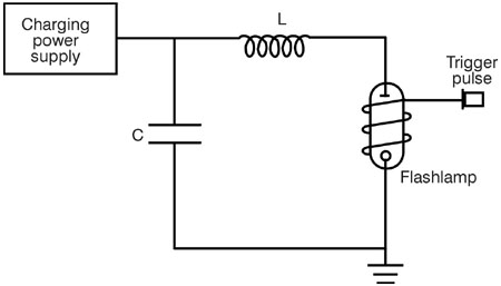
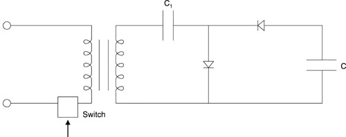
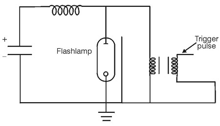
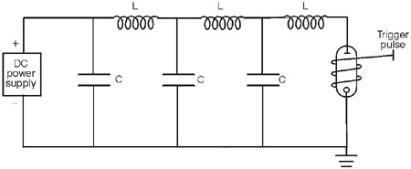
Power Supplies for Flashlamps (28) The power supply for a pulsed flashlamp performs a number of functions: • Charges a capacitor that stores electrical charge until the flashlamp is ready to fire. • Provides a trigger pulse that initiates the pulse. • Controls the flow of current during the pulse to control the pulse shape. (29) A prototypical circuit that performs all these functions is shown in Figure 4. The charging power supply charges a capacitor C, which holds the charge until the pulse is desired. Then the trigger circuit delivers a high-voltage pulse that breaks down the flashlamp and initiates the current flow. The capacitor discharges through the flashlamp, with the pulse characteristics controlled by the values of C, inductance L, and resistance of the flashlamp, to provide the desired pulse shape. We will discuss all these functions in turn. We will conclude the discussion of power supplies with a description of a variant method of operation called simmer or pseudosimmer.
Fig. 4
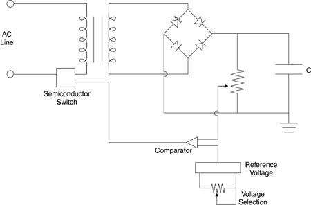
Charging Power Supply (30) The function of the charging power supply is to charge the energy-discharge capacitor. The charging must be completed within the interpulse time of the laser. (31) In most cases the charging power supply contains a transformer and a rectifier bridge. These elements supply the required DC voltage to charge the capacitor to a preset high voltage from an AC line. In addition, the charging circuit contains a semiconductor switch, such as an SCR. The function of the switch is to turn off the charging voltage when it reaches the selected value. The switch is initially on, and is turned off when the voltage across a parallel resistor reaches a value chosen by the operator. Figure 5 shows the main elements of the circuit to charge the capacitor C, including the generation of the signal to turn off the charging. The DC voltage is generated by the transformer and rectifier bridge. A signal proportional to the voltage across the capacitor is generated by a voltage divider with high resistance. This signal is fed to a comparator and compared to a reference voltage. When the voltage across the voltage divider rises to the desired value, the output of the comparator turns off the semiconductor switch and stops the charging of the capacitor. A knob on the control panel allows variation of the reference voltage so that the operator can select the final charging voltage.
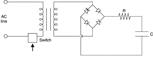
Fig. 5 (32) The circuit as shown in the figure contains no provision for limiting the current that charges the capacitor. When the charging begins, the capacitor is discharged and appears to be a short circuit. To protect the diodes, transformers, and other circuit components, the current must be limited. This is frequently done with a resistor as the current-limiting component, as illustrated in Figure 6. In this figure and in the following figures, the details of the voltage sensor and the input to the semiconductor switch are suppressed. The circuit shown in this figure is simple and straightforward, and is adequate when the pulse-repetition rate is low and the time available to charge the capacitor is relatively long. Then the current is relatively low and the losses in the resistor will not be too high.
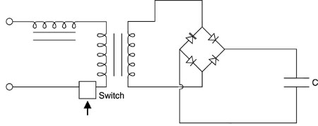
Fig. 6 (33) At higher pulse-repetition rates, the time available to charge the capacitor is short and the current must be higher. Then losses in the resistor become unacceptably high and other current-limiting methods are required. One such method is shown in Figure 7, which uses an inductor in the primary of the transformer to limit the current. When the capacitor is discharged and the current would otherwise be large, the current is limited by the inductive reactance.
Fig. 7 (34) When the pulse-repetition rate becomes still higher and approaches the frequency of the power line, few cycles of the power line fall within the charging period. The charging current comes in surges, one surge for each half cycle of the power line. This makes the charging erratic and unreproducible, because of fluctuations in the relationship of the charging surges and the temporal window available to complete the charging. A resonant charging circuit to counter this problem is shown in Figure 8. The capacitor C1 is much larger, perhaps ten times larger, than the discharge capacitor C, and acts as a filter. The current flows during the first half cycle of the resonant frequency and charges the discharge capacitor to a voltage two times the source voltage.
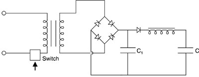
Fig. 8 (35) At still higher pulse-repetition rates, one uses a continuous-arc lamp source to excite the laser rod continuously. The pulses are triggered by an optical switch in the laser cavity. This allows operation of Nd:YAG lasers at frequencies up to tens of kilohertz. The operation of continuous-arc lamp sources will be described in Module 4-5. (36) A different approach to current limiting is shown in Figure 9. This uses a small capacitor C1, with capacitance much less than C, in a voltage-doubling circuit. At each current surge from the rectifier circuit, the small capacitor is charged and then transfers its charge to the discharge capacitor.
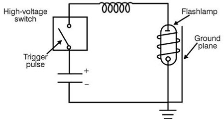
Fig. 9 (37) In typical cases with small lasers, one may encounter discharge capacitors with capacitance in the range of a few hundred microfarads charged to voltages in the range of from 500 to 2000 volts. Since the energy, E, stored in a capacitor of capacitance, C, charged to voltage, V, is: E = 0.5 CV 2 Equation 4 the typical energy stored may be in the range of several hundred joules. But there are much larger lasers that may require capacitive energy storage up to megajoules. Triggering (38) Four types of triggering circuits have commonly been used as circuitry to trigger the flashlamp: • Overvoltage • External • Series • Parallel (39) The last three are used most often with solid-state lasers. The advantages and disadvantages of the triggering mechanisms will be discussed. (40) An overvoltage trigger circuit is shown in Figure 10. In this figure and the three that follow, the emphasis is on the triggering portion of the circuit. The circuit diagram for the power supply itself is simplified; this will be described in more detail later. In overvoltage triggering, the initial bias voltage across the lamp is sufficient to break down the gas in the lamp and begin the discharge. The voltage is applied to the lamp when the switch is closed. The type of switch used is usually a hydrogen thyratron, a triggered spark gap, a mercury ignitron, or a silicon-controlled rectifier (SCR). A modern circuit may have a single 1000-volt MOSFET or VFET transistor switch stage. In cases where a few thousand volts need to be switched, isolated stages of MOSFETs or VFETs can be cascaded to meet the voltage requirements. Overvoltage triggering provides a relatively simple approach to triggering, but it does require the use of a relatively expensive high-voltage switch.
Fig. 10 (41) In external triggering, the high-voltage trigger signal is applied directly to a trigger wire outside the lamp envelope, as illustrated in Figure 11. This type of circuit can use small, lightweight, and inexpensive transformers. The main advantage of external triggering is that the energy-discharge circuit is independent of the trigger circuit. The inductor in the pulse-forming network (to be discussed later) is not affected by the trigger pulse. A major disadvantage of external triggering circuits is that the trigger voltage is exposed. Therefore, this method of triggering is not recommended for use at high altitudes or in humid environments.
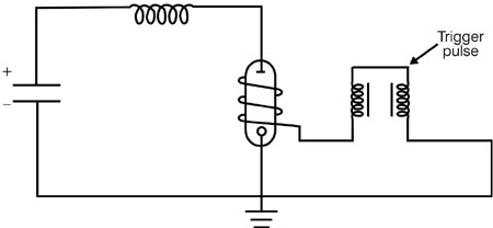
Fig. 11 (42) In series triggering, the secondary winding of the trigger transformer is in series with the energy-storage capacitor and the flashlamp. This circuit is shown in Figure 12. When the lamp is ignited, current flowing in the circuit saturates the transformer core. This means that the saturated inductance of the transformer serves as the pulse-forming inductor. This reduces the overall component count in the circuit. Series triggering offers reliable and reproducible triggering. Another advantage of series triggering is trigger reliability at low capacitor-charging voltages. Also, this method yields safe and reliable operation in severe environments because all high-voltage sources can be encapsulated. Disadvantages of series triggering include large size, heavy weight, and high cost of the trigger transformer and large saturated secondary inductance.
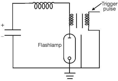
Fig. 12 (43) In parallel triggering, the secondary of the trigger transformer is connected to the lamp in parallel. A circuit is shown in Figure 13. A capacitor or a diode is needed to isolate the secondary winding of the transformer from the energy-storage capacitor. Parallel triggering retains the advantages of series triggering and has an additional attractive feature of requiring only a small external triggering transformer. The disadvantages of this circuit involve the requirements of the isolating element. If a capacitor is used, as is illustrated in the figure, the trigger circuit needs a large pulse-forming inductor. If a diode or train of diodes is used, it adds parasitic losses to the circuit. The requirements placed on the diode are very exacting. It may not be possible to obtain a suitable diode, and if one is available, it will be very expensive.
Fig. 13 (44) In addition, reliable triggering requires the use of a ground plane near the flashlamp. This is a factor independent of the method of triggering. Often, this stable voltage reference is a wire wrapped around the lamp. The entire arc length should be spanned to allow triggering to occur at the lowest values of voltage. The presence of the ground plane is indicated in the figures above. (45) The exact value of the trigger voltage is difficult to specify. Typically, it is in the kilovolt range and decreases as the bias voltage (the main-capacitor voltage) on the lamp increases. But there are variations even among lamps of nominally identical manufacture. The manufacturer usually specifies nominal trigger conditions for specific models of flashlamps. (46) Also, in addition to having the appropriate values of trigger and bias voltage, the relation of the polarities of the voltages must be correct. Table 1 defines four different trigger modes based on trigger-system polarity and the polarity of the energy-storage system. These modes are independent of the trigger method used. Table 1. Trigger Modes
(47) The first and third modes should not be used for external triggering. The second and third modes are not recommended for serial triggering because the trigger drives the core toward saturation in the wrong direction, opposite from the direction it would be driven by the main current pulse. The fourth mode is recommended for applications in which a wide range of bias voltages may be encountered or in which there is a risk of the lamp’s self-firing. The second mode is desirable when the lamp must be fired reliably at low power-supply voltages. (48) Another consideration is the length of time required for the streamer to form. The trigger pulse must be long enough to ensure that the spark streamer has time to bridge the space between the two electrodes. If the trigger pulse is too short for the streamer to form, erratic triggering will occur. A value of 60 nanoseconds per centimeter of arc length is recommended. (49) As an example, given a two-inch arc length, how long should the trigger pulse be? The length of the arc in centimeters is 2 ´ 2.54 = 5.08 cm. The duration of the trigger pulse should be 5.08 cm ´ 60 ns/cm = 305 ns.
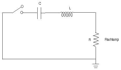
Control of Pulse Shape (50) The flashlamp operates in an RLC circuit, as shown in Figure 14. The resistance, R, is provided by the flashlamp; the inductance, L, by the series inductance; and the capacitance, C, by the discharge capacitor. The influence of the triggering circuit components is minimal and can be ignored. The circuit constitutes a pulse-forming network, and the shape of the current pulse depends on the values of R, L, and C.
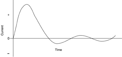
Fig. 14 (51) The analysis of an RLC circuit with a constant resistor is relatively simple. But as we have seen, the resistance of the flashlamp is not constant, but changes through the duration of the pulse. For the moment, however, we will discuss the current waveforms that are available in the context of a constant resistance L. If the relationship of R, L, and C is such that R < 2 (L/C)1/2, Equation 5 then the circuit is said to be underdamped and the current waveform will be as shown in Figure 15. There will be oscillations in the current, with the current reversing and swinging negative at some times. This is highly undesirable. The flashlamps are designed for current flow in one direction and can be damaged by current reversals. Also, the current will pass through several nulls during the discharge. This will make the pumping of the laser erratic.
Fig. 15
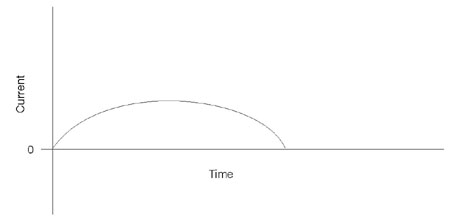
(52) If we have R > 2 (L/C)1/2, Equation 6 the circuit is said to be overdamped and the current waveform will be as shown in Figure 16. There are no current reversals, but the peak value of the current is limited and the pulse is stretched out, usually to a value longer than desired.
Fig. 16
(53) If we have R = 2 (L/C)1/2, Equation 7 the circuit is critically damped and the current waveform will be as shown in Figure 17. This is the desirable case. There are no current reversals. The current rises with a reasonably short rise time to its peak value and then falls over a somewhat longer period to zero and ceases. One obtains desired high peak values of current in this case.
Fig. 17 (54) The time-varying resistance of the flashlamp during the pulse complicates the analysis so that it is not possible to use the expressions above. But it is still possible to adjust the circuit components to avoid the undesirable cases of underdamped and overdamped behavior and to obtain the desirable case of critically damped behavior. The behavior of circuits containing flashlamps has been studied extensively, and guidelines have been developed that allow the specification of the proper values of the circuit components to yield a critically damped pulse with specified parameters. (55) We shall not go through the derivation of the equations here, but shall present only the results. Generally specified are the type of flashlamp to be used, the energy E0 to be discharged, and the pulse duration, tp, specified as the time between the points on the leading and trailing edges of the pulse at 10% of the peak amplitude. Given these inputs, one desires to know the values of capacitance C, inductance L, and charging voltage V, to yield a critically damped pulse with these characteristics. (56) These values may be obtained from the following equations: C = (0.09 ´ E0 ´ tp2/K04)1/3 Equation 8 L = tp2/9C Equation 9 V = (2E0/C)1/2 Equation 10 (57) Here K0 is the lamp-impedance parameter, defined earlier. Its value should be known for the specified flashlamp. Use of the above three equations will then allow one to solve for the proper circuit parameters. (58) As an example, consider a flashlamp with a lamp-impedance parameter of 13 ohm-ampere1/2. One desires to discharge 100 joules of energy through this lamp in a pulse of 500-microseconds duration. According to Equation 8 the capacitance should be C = [0.09 ´ 100 ´ (500 ´ 10- 6)2/(13)4]1/3 = 0.199 ´ 10- 3 farads = 199 microfarads. (59) Then the inductance L = (500 ´ 10- 6)2/(9 ´ 0.199 ´ 10- 3) = 1.40 ´ 10- 4 henry = 140 microhenrys. Finally, the voltage V = ( 2 ´ 100/0.199 ´ 10- 3)1/2 = 1002 volts. (60) The pulse circuit described above has a single inductor and a single capacitor and is referred to as a single-mesh network. In many cases, the circuit will contain two or more LC networks in series. This situation is called a multiple-mesh network. This is illustrated in Figure 18, for the case of three meshes.
Fig. 18 (61) The purpose of multiple-mesh networks is to control the pulse duration better and to make the top of the pulse more flat, so as to provide more constant pumping of the laser through the duration of the pulse. The use of multiple-mesh networks will change the pulse shape in the fashion shown in Figure 19. With a single mesh, the level of excitation of the laser is high at the beginning of the pulse, but decreases toward the end. With the multiple-mesh network, the peak of the pulse is lower, but it remains higher later. The result is that the laser pulse shape also has a flatter top.
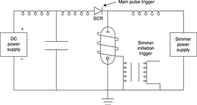
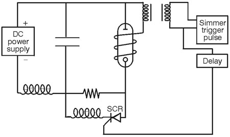
Fig. 19 (62) Again, we will not describe a detailed analysis of the multiple-mesh network, but will simply present the equations relevant to its design. If the total inductance and capacitance of the network are LT and CT respectively, the impedance, Z, of the network is adjusted to match the impedance of the flashlamp. The impedance of the flashlamp is taken as the resistance of the lamp when it has been broken down. The resistance of the flashlamp has been given previously by Equation 3. To select a value of resistance, one must assume a value for the electrical current near the peak of the pulse. The design of the circuit becomes an iterative process. One assumes a value for the current, calculates the flashlamp resistance, matches the impedance Z to it, and calculates the circuit parameters from the equations presented below. Then one calculates the current that would flow in that circuit and compares it to the value originally assumed. If the values do not match, one must recalculate the circuit parameters using the new starting current and repeat the calculation until it converges. (63) In this discussion, we deal with a pulse duration td defined as the time between the points where the amplitude is 70% of the peak value. Then, with the pulse energy E and pulse duration specified, the equations for the capacitance, inductance, and voltage V are: CT = td/2Z Equation 11 LT = tdZ/2 Equation 12 V = (2E/CT)1/2 Equation 13 For the circuit impedance, one has: Z = (LT/CT)1/2 Equation 14 (64) Given the flashlamp parameters, an assumed peak electrical current, the energy to be discharged, and the desired pulse duration, one has enough equations to solve for the capacitance, inductance, and voltage. (65) If there are N stages in the mesh, the capacitance C and inductance L of each stage are: C = CT /N Equation 15 L = LT /N Equation 16 (66) One may adjust the rise time of the pulse by varying N. The rise time tr (from 10% to 80% of the peak) is given by: tr = (LT CT)1/2/N Equation 17 (67) The rise time should not be made too short or it will result in damage to the lamp, including sputtering of the electrodes and crazing of the envelope. (68) The fall time tf, for the pulse to decrease from 80% to 10% of its peak value, is given by: tf = 3 tr Equation 18 (69) Thus, given the desired rise time of the pulse, the parameters of the flashlamp, and the total energy, one may design a multiple-mesh circuit to provide the desired parameters. Simmer Mode and Pseudosimmer (70) Many pulsed solid-state laser systems incorporate driving circuits known as "simmer mode" or "pseudosimmer mode" circuits. These circuits maintain a steady-state partial ionization of the lamp during the time the lamp is not flashing. This is done by establishing and maintaining a low-current DC arc between the lamp electrodes. These circuits offer many operational advantages. (71) The simmer method of operation is used in applications where the pulse-repetition rate exceeds 100 Hz. At high rates, the flashlamp does not have time to return completely to its nonconducting state between pulses. It will not recover its ability to hold off the applied voltage before the next pulses. The energy-storage capacitor will not be able to be recharged. Its charge would be dissipated through the flashlamp, which is still in a conducting state. A series switch (SCR, high-voltage FET, and so on) in the energy-storage circuit is used to isolate the capacitor voltage from the flashlamp. (72) A typical simmer mode circuit is illustrated in Figure 20. A low-power DC discharge is present in the lamp during the interval between pulses. When it is desired to pulse the laser, a trigger pulse is applied to the switch. The energy stored in the capacitor is then delivered to the lamp through the switch. The flashlamp, already partially ionized, fires easily. Typical simmer currents may be in the 50-100-milliampere range, with power dissipation in the 10-15-watt range.
Fig. 20 (73) The advantages of simmer mode operation include increased lifetime for the flashlamp, reduced jitter in the timing of the pulse, improved pulse-to-pulse reproducibility of the flashlamp output, capability for operation at higher values of pulse-repetition rate, and better control of lamp status. The control of the lamp status is achieved by monitoring the so-called keep-alive current—the current that flows through the lamp between pulses. If there is a short circuit or a broken flashlamp, the triggering can be disabled and no discharge will occur. This feature is usually used in systems with multiple flashlamps. In addition, the use of the simmer mode leads to increased efficiency of the flashlamp for pumping Nd:YAG lasers. (74) At lower pulse-repetition rates, maintaining a simmer discharge during the longer interval between pulses wastes power. In this case, one may use a pseudosimmer mode circuit. Such a circuit is shown in Figure 21. For most of the time between pulses, the current in the lamp is off. It is put into a simmer mode shortly before the next pulse is due. At that time, the lamp is ignited by a conventional external trigger circuit. A current limiter (series resistor) restricts current flow in the circuit to about 50 milliamperes. After a delay of around 100-200 microseconds, the switch is triggered. This shorts out the limiting resistor and allows the main discharge to occur.
Fig. 21 (75) In the pseudosimmer mode, the discharge is off for most of the relatively long interval between pulses. This saves most of the power that would be used by keeping the lamp in continuous simmer operation. Then the simmer mode is turned on shortly (100 microseconds or so) before the main pulse will occur. This mode of operation has all the advantages of simmer mode operation. It is usually found in small, lightweight laser systems.
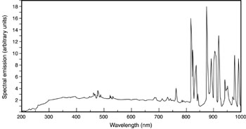
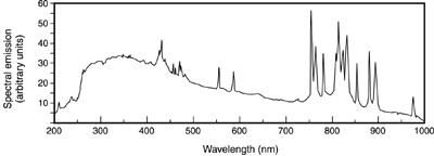
Optical Characteristics (76) The light emitted from flashlamps contains both discrete line structure and continuum radiation. The line structure arises from transitions between energy levels of the atoms and ions in the discharge. The continuum radiation is blackbody radiation, characteristic of the temperature of the plasma in the discharge. The exact spectral content is complicated, depending in a complex way on the gas type and pressure, the current, the plasma temperature, and the electron density. In addition, the spectral content of the light can change during the course of the pulse. (77) Generally, for low values of energy input to the flashlamp, the line emission dominates. As the energy increases, the continuum radiation increases relative to the line emission. This is shown in Figures 22 through 25. These four figures are all for linear flashlamps with a bore diameter of 6 millimeters and an arc length of 7.62 centimeters, and with clear fused-quartz envelopes. Figure 22, for xenon at low energy input, shows the spectral emission over the range from 200 to 1000 nm. The results in this figure and in the following three figures were obtained using a detector located 50 cm from the flashlamp and viewing it normal to its long axis. The data present the total emission over the duration of the pulse. The light consists mainly of narrow spectral lines near the long-wavelength end of the spectrum.
Fig. 22
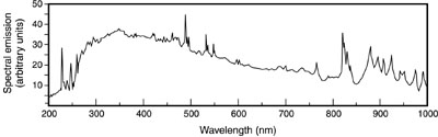
(78) Figure 23 shows the output from the same xenon-filled flashlamp, but at increased energy input. The line emission is still present, but the continuum radiation has increased substantially, especially at the short-wavelength end of the spectrum.
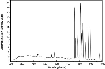
Fig. 23 (79) Figures 24 and 25 present results for krypton-filled lamps, at low and high energies respectively. The same behavior is apparent. The emission is dominated by sharp lines at low energy, and a strong short-wavelength continuum develops at higher loading.
Fig. 24
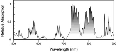
Fig. 25 (80) The conversion of the electrical input energy to optical radiant energy can be high, often in the 40-60% range for xenon and in the 25-30% range for krypton. Because of the higher efficiency, xenon gas fills are preferred for many applications. (81) For pumping of Nd:YAG lasers, the strong line structure of the krypton emission in the 800-nm spectral region provides a better match to the absorption lines of Nd:YAG. The absorption spectrum of Nd:YAG is shown in Figure 26. Nd:YAG has very strong absorption near 800 nm. These absorption lines are coincident with the strong emission of krypton flashlamps. Thus, krypton flashlamps are often used for excitation of Nd:YAG lasers. The main pump bands for krypton lamp excitation are the broad bands centered near 750 and 800 nm. Recently, semiconductor laser diode sources (see module 4-6) have become important for pumping Nd:YAG lasers. Their light is absorbed in the narrow peak near 810 nm.
Fig. 26 (82) The output of the flashlamp emerges through the envelope. The spectral absorption of the envelope will affect the spectral content. Most often the envelope is fused silica (silicon dioxide, also called fused quartz). This is transmissive over the range from 200 to 4000 nm. Thus the short-wavelength ultraviolet light can emerge from the flashlamp. The ultraviolet light can produce ozone by interacting with oxygen. To prevent this, sometimes fused silica with a small amount of titanium is used. This changes the short-wavelength transmission limit to 250 or 300 nm and inhibits the formation of ozone. (83) Cerium-doped quartz has also been used as an envelope material. This eliminates ultraviolet light at wavelengths shorter than 310 nm. It converts the ultraviolet to fluorescence in the 400-650-nm range, so these flashlamps show enhanced output in that spectral range.
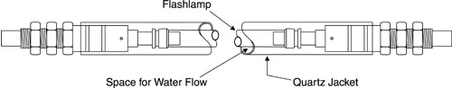
Mechanical Characteristics (84) Important considerations in the structure of flashlamps include the envelope, the electrodes, and the seal of the electrodes to the envelope. (85) The material used as the envelope for flashlamps for laser-pumping applications is silica fused quartz, also known as vitreous silica or fused quartz. It has the chemical composition silicon dioxide. It is transparent over a broad spectral range, from the mid-infrared well into the ultraviolet, as we discussed in the section on optical characteristics. It also has high thermal conductivity and a relatively low thermal-expansion coefficient. These two properties are the main reasons for the choice of fused silica for use in the hostile environment of the high-current discharges characteristic of laser pumping. (86) Glass is sometimes used as the envelope material for flashlamps that do not have to carry very large currents. These applications include photography and stroboscopic applications, but glass cannot withstand the severe thermal environment and shock associated with pumping pulsed solid-state lasers. (87) Water-cooled flashlamps may have standard envelopes mounted in an outer quartz tube and sealed with O-ring seals (see Figure 27). Threaded mounting lugs allow connection to the water supply. At the end of the life of the flashlamp, the outer tube and fittings may be removed and used with another flashlamp.
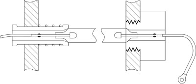
Fig. 27 (88) The electrodes in flashlamps must withstand high temperature and high electrical-current density. Because of the high melting temperature of tungsten, some form of tungsten is used. The tips of the anodes are generally either pure tungsten or thoriated tungsten. (Thoriated tungsten is tungsten impregnated with thorium oxide. It is easier to machine than tungsten.) The cathode tip is usually formed of a so-called tungsten dispenser matrix. The dispenser matrix is porous tungsten impregnated with a material that lowers the work function of the surface and allows it to emit more electrons at a given temperature. Sometimes barium strontium aluminate has been used in the dispenser, but each manufacturer has its own proprietary materials for the dispenser matrix. (89) Because of the lowered work function of the cathode, current will flow in only one direction in a flashlamp without damage. It is important to ensure that the lamps are installed in the circuit in the proper orientation. Conventionally, many manufacturers mark the anode end of their arc lamps red. (90) The tips of the anodes in flashlamps are rounded. This allows spreading of the anode current over a larger area. The cathode tips have a larger surface area to help reduce sputtering and erosion because of bombardment by energetic ions. The cathodes are subject to erosion because of the ion bombardment. (91) There are two commonly used structures for sealing the electrodes into the quartz tubes for flashlamps: tungsten rod seals and end cap seals, also called solder seals. (92) A tungsten rod (or graded seal) lamp has a thin tungsten rod welded or brazed to the electrode. The seal between the tungsten and the quartz envelope of the lamp is made with one or two glasses that have values of the coefficient of thermal expansion intermediate to the values of tungsten and quartz. This arrangement reduces stress arising from thermal expansion at material interfaces. Lamps with this construction can be processed at high temperature in vacuum to reduce contamination. This design also allows operation of the lamps at high temperature. Tungsten rod seals are used in flashlamps for pumping solid-state lasers because of their relatively long life, their capability for operation with high electrical currents, and their ability to handle high average power. (93) End cap seals, or solder seals, incorporate a seal between a circular band of invar (a nickel alloy with a low thermal-expansion coefficient) and the quartz tube. The circular band constitutes the end cap. The seal is made with a lead-indium solder with a melting point of around 350° C. The main reason for use of the solder seal is its lowered manufacturing cost. Because of the relatively low melting point of the solder, the seals cannot be processed at high temperature, in contrast to the rod seals. As a result, solder seals may have a shorter lifetime and poorer reliability. They are also restricted to operation at moderate currents, because they cannot tolerate the heating associated with high-current operation. (94) The mountings and supports for flashlamps are another important consideration. The end mountings often serve as both the physical support of the lamp and its electrical connection. There are many possible variations for end mountings. It is extremely important that the mountings be secure, but not exert stress on the lamp seal or housing. The seals of flashlamps are susceptible to failure when they are stressed, especially when they are stressed in a direction perpendicular to the long axis of the tube. The support must be flexible, yet firm enough to support the lamp well and to form a good electrical contact that can carry high values of electrical current. (95) Two approaches, of the many possible, are shown in Figures 28 and 29. Figure 28 shows a mount suitable for use with flashlamps cooled by gas and operating at relatively low average power. The electrical connection is made with a ring terminal. Figure 29 shows a design, suitable for use with water-cooled flashlamps, that avoids contact between the electrical connections and the cooling water. Problems may arise because the end terminal is not cooled by the water and high temperatures may be reached there.
Fig. 28
Fig. 29
(96) Some laser manufacturers have developed mounting fixtures that allow the flashlamps to be removed and replaced without opening the laser cavity.
Cooling for Flashlamps (97) The main goal of lamp cooling is to keep acceptable average temperatures for the lamp electrodes and internal envelope surface. When the temperature in these regions exceeds safe values, lamp lifetime is reduced because of erosion of material. Sputtering of the electrodes and vaporization of the inside surface of the quartz envelope result from exceeding safe temperature values. Other effects of overheating include buildup of stress in the lamp envelope. This may lead to bending or fracturing of the envelope. (98) The amount of cooling required is determined by the average power density (that is, the average input power per square centimeter of the inside lamp wall) at which the lamps are operated. Flashlamp power densities vary widely, according to application, so that cooling requirements are also varied. Other factors affecting cooling include the type of quartz in the envelope, the thickness of the envelope, and the fill gas and pressure. (99) Flashlamps operating at power densities below the point at which liquid cooling is required normally use natural air as a cooling gas. However, in some cases an oxygen-free gas may be needed. If one uses an undoped quartz envelope, ozone generation occurs with each discharge. Then a gas like nitrogen may be used in gas-cooled systems. (100) Gas-cooled flashlamps have an envelope thickness of between one and 2.5 mm. Xenon-filled flashlamps at 450-torr fill pressure with 1-mm-thick natural fused-quartz envelopes may be safely driven up to power densities of 15 watts/square centimeter in systems that are cooled by convective gas cooling. (101) Flashlamps in a stream of flowing gas can operate safely at twice the average power density for convective gas cooling. This guideline depends on the temperature of the cooling gas and the velocity, direction, and uniformity of the flow of the coolant gas over the lamp. (102)Flashlamps operating above the maximum limits of power density for forced gas cooling must be liquid-cooled. Average power densities up to 200 watts/square centimeter are often specified for liquid-cooled xenon flashlamps with 450-torr pressure, one-millimeter-thick envelopes of fused quartz. This limit is conservative because it is intended to cover a wide range of operating parameters and coolant velocities. (103) Deionized purified water is perhaps the most widely used liquid coolant. The purity of the water must be high to prevent etching of the envelope and the buildup of dark deposits on the outside of the envelope. Deionized water must be used in systems where the liquid coolant and the electrical connections are in contact. This will prevent erosion of the electrical contacts through electrolysis and will also prevent shorting of the electrical pulse. (104) The construction of the lamp and the placement of the electrodes within the lamp envelope usually ensure that the requirements for electrode cooling will be satisfied when there is adequate cooling for the envelope. However, when liquid cooling is used with flashlamps of rod-seal construction, one must ensure that high-velocity, turbulent flow exists in the region where there is shrinkage of the quartz over the anode. (105) Table 2 shows cooling guidelines recommended by flashlamp manufacturers. The wall loading in the first column is calculated by dividing the average input power (energy per pulse multiplied by pulse-repetition rate) by the total inside wall surface area.
Table 2. Typical Manufacturers’ Cooling Recommendations
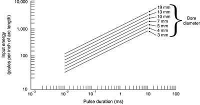
Failure Mechanisms and Lifetime (106) Flashlamps used for optical pumping of high-power solid-state lasers have finite lifetime. Their lifetime is reduced as the input energy is increased. We may distinguish two failure modes: The first, a catastrophic failure mode at high lamp input, results in explosion of the lamp. The second mode is noncatastrophic and gradual, and is characterized primarily by decreased light output from the lamp. (107) At some value of input energy, a flashlamp will explode in a single pulse. The heating and shock from the rapid formation of the high-current-density discharge are enough to shatter the envelope. The single-shot explosion energy depends on the diameter and length of the lamp. Figure 30 shows the explosion energy for flashlamps as a function of the diameter of the bore and the duration of the discharge of electrical energy through the lamp. The pulse duration here is specified as the time between the points at one-third of peak amplitude. The pulse length may be adjusted by varying the circuit parameters, including capacitance and voltage of the power supply and the value of the circuit inductance. The explosion energy is expressed in terms of the energy input to the lamp per unit length of the lamp. This value will cause the flashlamp to explode in one pulse.
Fig. 30
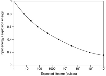
(108) Note that the pulse duration specified in Figure 30 is at the points where the pulse is at one-third its peak value. This is different from the pulse duration that we have used previously, which was at the 10% points. For a critically damped pulse, the value at the 10% points is about 25% longer than the value at the one-third points. (109) Some manufacturers quote an explosion-energy constant as one of the specifications for a flashlamp. The explosion-energy constant Ke is in units of watt (second)1/2. The explosion energy Eex in joules is then given by: Eex = Ke (T/3)1/2 Equation 19 where T is the pulse duration in seconds (between the 10% points for a critically damped pulse). (110) At values below the explosion energy, but at a significant fraction of the explosion energy, the lamp is still subject to explosion after a number of shots. The shock from the discharge forms microcracks in the envelope, cracks that expand with each pulse. Eventually, the lamp will fail catastrophically with repeated firing. (111) To obtain long life for flashlamps, the lamp must be operated at values of electrical input energy much below the explosion energy. The lifetime of a xenon-filled flashlamp with a fused silica envelope has been found experimentally to vary according to the equation: N = (Eex/E0)8.5 Equation 20 where N is the lifetime of the lamp in pulses, Eex is the single-shot explosion energy as defined above, and E0 is the input energy per pulse. Thus, the lifetime of the lamp has a very strong power-law dependence, and the lifetime increases rapidly as the input energy is reduced. In this equation the lifetime is expressed as the number of pulses after which the light output of the lamp is reduced to 50% of its original value. (112) Figure 31 shows graphically how the lifetime is increased as the electrical loading is reduced. To obtain reasonably long lifetime, one should operate below 40-50% of the explosion energy. When the electrical input is restricted to lower values, perhaps 10 to 20 percent of the explosion energy, the lifetime may rise to millions of pulses. However, the user’s desire to obtain high-output energy from the laser often requires larger inputs to the flashlamp. Some trade-off must generally be made between the lifetime of the flashlamp and the output of the laser.
Fig. 31
(113) In a regime where the lamp is operated well below the explosion energy, the failure mechanism is generally not an abrupt failure. Rather, it is a gradual decrease in light output because the interior surfaces of the lamp dampen as material evaporates from the electrodes and redeposits on the flashlamp walls. Sputter of the anode is less of a factor, because the anode is bombarded only by electrons. (114) In the region of low loading, perhaps below about 20% of the explosion energy, the lifetime expressed by Equation 20 and Figure 31 is probably not as accurate as at higher input values. The lamp deterioration is a gradual aging process, not a mechanism affected by mechanical shock. Small variations in the cleanliness and processing of the flashlamps will have an effect. Thus, the curve at the right edge of Figure 31 should perhaps broaden into a range of values. (115) In addition, the arbitrary definition of the end of lamp life as a reduction in light output by 50% may not be adequate. It is likely that the operator of a flashlamp-pumped laser might replace the lamp before the reduction in light output reaches 50%. (116) Another factor affecting lifetime is the rise time of the pulse. A short rise time enhances the shock experienced by the envelope. For flashlamps operating at energies around 100 J, the rise time should be longer than 50 microseconds. When the input energy rises to the kilojoule region, the rise time should be longer than 200 microseconds. (117) We note that is important that the flashlamp be mounted in the circuit in the proper orientation. The lamps are intended to have current flow in one direction. If they are oriented in the wrong direction, excessive erosion of the electrodes may occur, shortening the lamp lifetime. Some manufacturers mark the anode end of their lamps with a red mark.
Selection of Flashlamps (118) We may now discuss the process of selecting a flashlamp, given specified operating parameters. The specifications that the manufacturer may quote for a flashlamp include the inside diameter of the envelope, the arc length (between electrodes), the impedance parameter K0, the explosion energy constant Ke, and the required trigger voltage and duration. (119) For a given application, the arc length, the pulse duration, the pulse energy, and the desired lamp lifetime are usually given. Thus, the task becomes one of determining the proper bore diameter. (120) First, using the desired lamp lifetime and the pulse energy, determine the required explosion energy, using Equation 20. Next, calculate the explosion energy constant Ke using Equation 19. Then determine the required bore diameter using the equation: d = 0.00016 Ke/L Equation 21 where the bore diameter, d, is in millimeters and the arc length, L, is in inches. (121) Having these results, turn to the manufacturer’s specification sheets and select a flashlamp with the proper bore diameter and arc length. If the calculation using Equation 21 yields a diameter lying between available bore diameters, choose the lamp with the next larger diameter.
Maintenance and Care (122) The following measures are recommended for the care and handling of flashlamps: 1. Use great caution and wear protective eyewear and gloves when handling, cleaning, removing, or installing flashlamps. 2. Do not mechanically stress flashlamps. 3. Do not chip or scratch the lamp envelope. 4. Do not allow the envelope to be contaminated by dirt, oil, fingerprints, or other contaminants. 5. Keep the lamp in its protective sleeve until it is ready for use. 6. If cleaning is needed, wipe the lamp carefully with lint-free tissue soaked in methanol. 7. If the envelope has deposits, change the deionizer cartridge, particle filter, and deionized water in the cooling system. Always use a high-quality deionized-water filter. This filter removes ions and oxygen, which can reduce lamp lifetime. 8. Keep the lamp away from static electricity. 9. When installing the lamp, do not stress the seals or the envelope. If lamp clips are used, stretch them out first with a pencil eraser for easier installation. If a solid lamp holder is used, make sure that no corrosion is present. 10. Check for the presence of the red mark indicating the anode end of the lamp. Ensure that the flashlamp is inserted in its holder in the proper orientation.
Safety Around Flashlamps (123) Flashlamps present several different types of hazards. These include explosion of the lamp, emission of ultraviolet radiation, and generation of ozone. (124) Explosion hazards arise because flashlamps operate at very large electrical currents that cause shock and pressure pulses inside the lamp envelope. This is especially true when the lamps are operated at high values of input energy. It should be noted that flashlamps that have been operated for a number of pulses without incident may still explode without warning. Since the flying shards of glasslike quartz from a lamp explosion could cause blindness or other injury, flashlamps must be operated in a protective housing. The enclosure must be strong enough to withstand a possible explosion and to contain the fragments of quartz. (125) In addition, improper handling or mechanical stress may lead to explosion. Thus, one should wear protective eyewear and gloves when handling, cleaning, or installing flashlamps. (126) High-intensity flashlamps may produce short-wavelength ultraviolet radiation that can cause burns to the skin and to the outer surface of the eyes. One should wear ultraviolet-absorbing eyewear and protective clothing when working in the vicinity of these lamps. (127) The short-wavelength ultraviolet radiation (wavelength around 200 nm) from high-intensity flashlamps may also produce toxic ozone. If the short-wavelength light is not required for the application, use of a flashlamp with an ultraviolet absorbing envelope is desirable. Flashlamps should be operated in well-ventilated areas to avoid possible buildup of ozone concentration.
Nd:YAG laser, with power supply capable of changing circuit components Discharge capacitors and inductors, as required Magnetic current probe Infrared detector with power supply Laser energy meter Oscilloscope Oscilloscope camera Cables and wiring as needed Laser safety eyewear appropriate for Nd:YAG laser Manufacturers data sheets for the flashlamps used in the laser
(128) In these procedures, you will design and construct a pulse-forming network to drive a flashlamp that pumps an Nd:YAG laser. You will measure the parameters of the current pulse and the laser pulse as the values of the circuit components are varied. You will operate the pulse-forming network as a single-mesh network and as a multiple-mesh network and compare the outputs in the two cases. (129) You will be working with energy-storage capacitors in these procedures. Employ all the appropriate safety measures as described in Module 4-1. Also use laser safety eyewear and follow the safety procedures appropriate for Nd:YAG lasers. (130) Choose a pulse duration at which you wish to work. This should be the desired pulse duration at the points where the pulse is one-third its peak value. Determine the single-shot explosion energy of the flashlamp for the Nd:YAG laser, either from the manufacturer’s specification or from Figure 30, using the dimensions of the particular flashlamp. Choose the pulse-discharge energy you wish to input to the flashlamp. This energy should be no greater than 40% of the single-shot explosion energy. (131) You should now have enough information to design a single-mesh pulse-forming network to provide a critically damped current pulse to the flashlamp. You have the pulse energy, the pulse duration, and the lamp-impedance parameter, either from the manufacturer’s specifications or calculated from Equation 2. Use Equations 8, 9, and 10 to calculate the proper capacitance, inductance, and voltage V0. Remember that the pulse duration as used in these equations is at 10% of the peak amplitude, and that specified in Figure 30 is at one-third the peak amplitude. For a critically damped pulse, the value at the 10% points is about 25% longer than the value at the one-third points. Remember to adjust the value of pulse duration originally chosen for this difference. (132) Assemble the components (capacitors and inductors) for the pulse-forming network as calculated in the step above, and insert them in the power supply for the flashlamp. (133) Before firing the flashlamp, check it for evidence of microcracks or crazing of the envelope, and for dark deposits on the inside of the bore. If there are indications of these defects, replace the flashlamp. (134) Place the current probe around the cable through which the main capacitor bank discharges through the flashlamp, and feed the output of the probe into the input of the oscilloscope. Direct the output of the laser into the energy meter. (135) Charge the capacitor bank and fire the laser. Start at a relatively low voltage and increase it in steps until you reach the voltage V0 calculated above. For each step, photograph the waveform of the current pulse using the oscilloscope camera. Record the value of the laser output energy for each firing. Measure the pulse duration for the current pulse from the photographs of the waveform. You may make the measurement at the 10% level or at the one-third level, but remember which you are using. Record the value of the pulse duration at each step. Also for each step, record the energy input to the flashlamp, as calculated from 0.5 CV2, where C is the capacitance and V is the voltage at that step. (136) How does the pulse duration at the calculated voltage V0 compare to the originally specified pulse duration? Is the current pulse critically damped? Plot the laser energy output as a function of the input energy. (137) Next, use the infrared detector to determine the waveform of the laser pulse. To avoid saturation of the detector, it may be necessary to direct the beam at a diffusely reflecting surface, like a piece of paper, and have the detector view the diffuse reflection. Move the detector far enough from the reflecting surface so that the detector output is not saturated. Feed the output from the detector circuit to the input of the oscilloscope. (138) Charge the capacitor to voltage V0 and fire the laser. Record the waveform of the laser pulse with the oscilloscope camera. Measure the duration of the laser pulse. How does it compare to the duration of the current pulse? Why should it be different? (139) In the next portion of the procedures, you will make measurements with a multiple-mesh network, specifically a three-mesh network. Making sure the capacitors are discharged, remove the capacitors and inductors and reassemble the circuit as shown in Figure 18. Each capacitor and inductor should have a value equal to one-third the total capacitance or inductance. (140) With the output of the current probe going to the oscilloscope and the output of the laser beam going to the energy meter, repeat the measurements of current-pulse duration and laser-pulse energy. Charge the capacitor bank and fire the laser. Start at a relatively low voltage and increase it in steps until you reach the voltage V0. For each step, photograph the waveform of the current pulse using the oscilloscope camera. Record the value of the laser output energy for each firing. Measure the pulse duration for the current pulse from the photographs of the waveform. Record the value of the pulse duration at each step. Also for each step, record the energy input to the flashlamp. (141) At voltage V0, compare the current waveform to that obtained with the single-mesh network. How has the waveform changed? How has the pulse duration changed? Plot the laser output energy as a function of the flashlamp energy. How has that plot changed? (142) Finally, use the infrared detector to determine the waveform of the laser pulse again. Lead the output from the detector circuit to the input of the oscilloscope. Charge the capacitor to voltage V0 and fire the laser. Record the waveform of the laser pulse with the oscilloscope camera. Measure the duration of the laser pulse. How does it compare to the duration of the laser pulse when the single-mesh network was used? (143) At the end of the procedures, make sure that all the capacitors are discharged.
Measurements of laser energy and current waveform versus voltage for single-mesh pulse-forming network:
1. 2. 3. 4. 5. 6. 7. 8. 9. 10. Duration of laser pulse = Measurements of laser energy and current waveform versus voltage for multiple-mesh pulse-forming network:
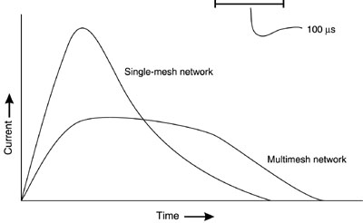
1. 2. 3. 4. 5. 6. 7. 8. 9. 10. 11. Duration of laser pulse =
General Comments from John Simcik 1. Explain why xenon is usually the preferred fill gas for flashlamps. Explain when krypton should be used. 2. Describe the emission spectra of xenon and krypton flashlamps for both low and high values of electrical loading. 3. Describe basic flashlamp operation. 4. Describe two different types of electrode-lamp seals and discuss their relative performance. 5. Explain why fused silica (fused quartz) is usually used as the flashlamp envelope material. 6. Describe four basic types of flashlamp trigger circuits. 7. Explain the simmer and pseudosimmer modes of flashlamp operation and discuss when they would be used. 8. Describe the process of selection of a flashlamp for a given application. 9. Sketch the flashlamp current as a function of time for underdamped, overdamped, and critically damped operation. Explain problems associated with underdamped and overdamped operation. 10. Describe how use of a multiple-mesh pulse-forming network changes the pulse shape as compared to a single-mesh network. 11. Explain proper maintenance and care of flashlamps. 12. Describe potential hazards associated with flashlamp operation and discuss methods to minimize them. 13. Given an explosion energy for a flashlamp of 500 joules and a pulse energy of 200 joules, calculate the expected lifetime of the flashlamp in pulses. 14. Given a desired input energy of 200 joules, a pulse duration of 600 microseconds, and a flashlamp with an impedance parameter of 17 ohm-ampere1/2, design a single-mesh circuit for pulsing the flashlamp in a critically damped discharge and determine appropriate values for capacitance, inductance, and charging voltage. 
Koechner, W. Solid-State Laser Engineering. 3rd ed. Berlin and New York: Springer-Verlag, 1992. Linear Flashlamps. ILN Technology, Sunnyvale, CA, n.d. Markiewicz, J. P., and J. L. Emmett. "Design of Flashlamp Driving Circuits." IEEE Journal of Quantum Electronics, QE-2 (1966): 707. An Overview of Flashlamps and CW Arc Lamps. Technical Bulletin 3. Sunnyvale, CA: ILC Technology, 1986. Perlman, D. F. "Characteristics and Operation of Xenon Filled Linear Flashlamps." Review of Scientific Instruments 37 (1966): 340. Wegrzyn, J., G. Patonay, and I. Warner. "Versatile Power Supply Circuit for Xenon Flashlamps." Review of Scientific Instruments 60 (1988): 90. Flashlamp Characteristics, EG&G Electro-optics, Salem, MA.
|