| This version reflects the comments of the core participants as reviewed and incorporated in accordance with CORD's FIPSE-supported Curriculum Morphing Project. | ||||||||||||||||||
Module 3-12 The output of a normal mode, pulsed, solid-state laser is generally a train of irregular pulsations—irregular in peak power, pulse width and frequency of occurrence. It is possible to remove these irregularities and at the same time greatly increase the peak power by a technique called Q-switching. Q-switching lasers normally emit only one giant pulse in an operational cycle. The pulse will typically have a time duration less than one microsecond and a peak intensity of megawatts (106 watts) or even gigawatts (109). This same technique may be applied to continuously pumped lasers to produce a train of Q-switched pulses with regular duration, peak power, and frequency of occurrence. The purpose of this module is to acquaint the student with the basic concept of laser Q-switching, Q-switching techniques, the characteristics of a Q-switched laser output, and the operation of a Q-switched laser. In the laboratory the student will operate a pulsed solid-state laser in the Q-switched mode. 
Upon completion of this module, the student should be able to: 1. Explain how energy is stored in the active medium of a laser. 2. Explain the basic principles of Q-switching. 3. Draw and label diagrams showing input pump energy, stored energy, amplifier gain, loop gain, and output power for a pulsed solid-state laser with the feedback mirrors removed, during normal mode operation, and during Q-switched operation. 4. Explain the factors determining the pulse duration and peak power of a Q-switched laser. 5. Explain why Q-switched lasers are less efficient than normal pulsed lasers. 6. Explain why some lasers cannot be Q-switched and give examples. 7. List and explain the four most important characteristics of Q-switches. 8. List the four most important types of Q-switch. Explain the operation and application of each type and rate each according to the four performance factors in the above objective. 9. Operate a pulsed slid-state laser in the laboratory in both the normal pulsed mode and the Q-switched mode. Measure the output characteristics of each and compare them. 
Basic Principles of Q-Switching Q-Switching is a mode of operating a laser in which energy is stored in the laser material during pumping in the form of atoms in the upper laser level and suddenly released in a single, short burst. This is accomplished by changing the feedback of the laser cavity. During pumping the HR mirror is effectively removed from the system, preventing lasing. After a large amount of energy has been stored in the active medium, the HR mirror is returned to proper alignment and operation, and most of the stored energy emerges in a single, short pulse. The extremely short, high-energy output pulse will occur at a predictable time. This makes the Q-switched laser an ideal transmitter source for rangefinders and surveillance radar. Q-switched lasers are also used to produce rapid, localized heating in materials. If the enormously high peak power in the output pulse is concentrated or focused, the intensity of the focused beam represents sufficiently high electromagnetic field strengths to ionize the air and cause "breakdown"—just like a high dc voltage between a spark gap. Q-switched lasers can be classified for study according to two criteria: 1. Whether they have a continuous or pulsed pumping source. 2. The methods and equipment used to "Q-switch" them. The first portion of this discussion will describe the theory of Q-switching using a pulsed pumping source for the laser amplifier. The discussion will then apply this technique to continuously pumped laser systems. The latter portion of the discussion briefly describes several Q-switching techniques.
Theoretical Basis of Q-Switching Q-switching is a method of controlling the laser energy by controlling the gain in the laser cavity. Thus an understanding of what happens in a laser during Q-switching requires a knowledge of energy transfer and gain in a laser. This section is a review of the factors affecting energy storage and gain in the active medium and laser cavity.
Absorption And Gain In The Active Medium The absorption of light in optical materials is described by Equation 1:
When the laser active medium is not being pumped, most of the atoms are in the ground state, and there are fewer atoms in each successively higher energy state. This results in a new absorption of the laser output wavelength by the active medium. In a three-level laser, absorption of the laser wavelength occurs from the ground state to the upper lasing level. Since most of the atoms are in the ground state and available for absorption, the active medium of a three-level system (ruby) will strongly absorb its own laser wavelength when pumping is not present. In the unpumped active medium of a four-level system, very few atoms are in the lower lasing level, and there is little absorption of the laser wavelength. The absorption coefficient of a material for any wavelength depends on the relative populations of the upper and lower energy states of the transition with that wavelength. This relationship is described by Equation 2.
As this equation indicates, absorption is greatest when the greatest difference in population exists with the highest population in the lower of the two states. The excitation mechanism of the laser moves atoms from the ground state to the upper lasing level. This reduces the difference in populations between the upper and lower lasing levels. When the two populations are the same, the absorption coefficient is zero, and there is no absorption of the laser wavelength. At this point stimulated emission and absorption occur at the same rate and balance one another. Additional pumping will increase the population of the upper lasing level above that of the lower lasing level creating a population inversion. When this occurs, the value of the absorption coefficient k in Equations 1 and 2 becomes negative. This indicates that the intensity of a light beam increases as it moves through the material. Thus, in this case, the laser active medium produces gain for the laser wavelength. Equation 3 is a mathematical expression for gain in the active medium for a laser.
This is the same form as Equation 2 with a = –k. This change in sign and notation is made so the gain coefficient is a positive number and so a higher gain coefficient indicates greater gain. The physical mechanisms for absorption and gain are the same, and the process that dominates the energy transfer depends upon the relative populations of the two energy states involved. A greater population inversion results in greater amplifier gain for the laser.
Energy Storage in the Active Medium Figure 1 is a simplified energy-level diagram of a four-level laser. Pumping adds energy to the active medium in the form of atoms raised in energy from the ground state to the pumping band. These decay rapidly to the upper lasing level. This state has a relatively long lifetime, and its population increases to produce a population inversion between states E3 and E2 of Figure 1. Thus energy is stored in the active medium in the form of excited atoms in the upper lasing level. This stored energy is released through stimulated emission to form the optical energy of the laser output. In lasers without Q-switching this energy is used immediately. The fluctuations in stored energy (and thus in amplifier gain) produce the spiked output characteristic of pulsed solid-state lasers. In CW lasers pumping and stimulated emission occur at constant rates producing a constant output. In either case the lasing process constantly uses the stored energy depleting the population inversion. However, if lasing is interrupted while pumping continues, both stored energy and amplifier gain can be increased to levels greater than those associated with the normal lasing process.
Fig. 1
Loop Gain of the Optical Cavity Figure 2 shows the optical cavity of a normal mode, pulsed solid-state laser. It consists of a laser rod between two plane parallel mirrors as described in Module 3-5, "Pulsed Solid-State Laser Systems." The loop gain of such an optical cavity is the gain experienced by the light signal in one complete round trip of the laser cavity. Factors contributing to loop gain are two passes through the amplifier, reflection from each mirror, and losses within the cavity. Equation 4 is an expression for loop gain.
Fig. 2
If the loop gain is greater than one, the signal strength within the optical cavity increases with each round trip of the laser cavity. Since the output power is directly proportional to the strength of the optical standing wave in the cavity, the laser power also increases. If the loop gain is less than one, the output power of the laser decreases. CW lasers in steady-state operation have a constant loop gain of 1.0. The conditions for lasing to begin in any laser may be determined by setting the loop gain equal to 1.0 and solving Equation 4 for Ga. This yields Equation 5.
This equation indicates that lasing will begin when the amplifier gain is sufficient to overcome all optical losses from the laser cavity, including the laser output.
Q-Switching and Gain The term "Q," as related to the operation of lasers, is used to describe the "quality" of the resonant cavity in terms of "how well it couples the intracavity signal back into the amplifier." In a practical way we can relate "Q" to the losses in the feel "loop" through the "cavity." In this trip, the signal encountered gain (became more intense) when it traveled through the laser amplifier rod, and encountered losses when it reflected off the mirrors, and entered and left the laser rod. It also encountered losses from diffraction and imperfect optical quality of the laser rod and mirror surfaces. If the signal was larger after it made a loop through the cavity, then in successive trips it will "build up" or become more intense, and lasing will occur. A laser output is observed because a percentage of the optical signal inside the cavity is transmitted through the partially-reflecting output mirror. When a laser is "Q-spoiled," a physical change is made in the feedback loop (resonant cavity) which drastically lowers the effective reflectance of the cavity during optical pumping. This prevents the system from lasing, and allows the population inversion to increase without an output being generated—resulting in an increase in amplifier gain (Ga) and stored energy in level 3. At the time of maximum population inversion (usually near the end of optical pumping) the "Q" is switched back to a high value by reforming the cavity, causing the system to lase, and thereby releasing its available, stored energy in one, short "giant pulse." Q-switching is accomplished by introducing large losses in the optical cavity of the laser during pumping. This prevents the loss of stored energy due to lasing until the stored energy and amplifier gain both reach a high value. The loss is then reduced to its lowest value, resulting in a loop gain that greatly exceeds that possible without Q-switching. This high gain results in a very quick buildup of the light signal in the cavity producing strong stimulated emission and using most of the energy stored in the active medium to produce a single short-duration, high-peak-power pulse. A Q-switch is essentially a shutter placed between the active medium and the HR mirror. With this shutter closed, the HR mirror is blocked preventing feedback and lasing. When the amplifier gain reaches a predetermined value, the shutter is opened to increase the cavity quality. Four major Q-switch types are discussed later in this modules.
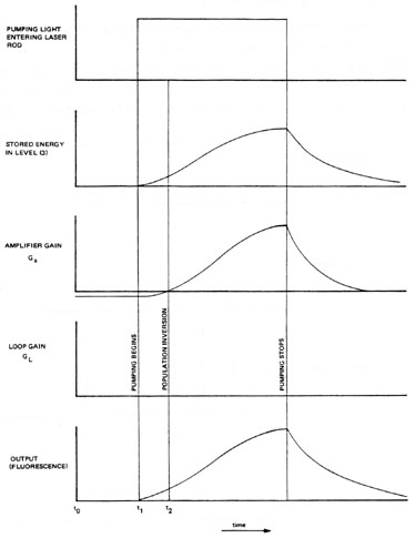
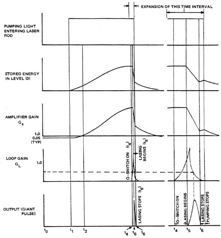
Effects of Q-Switching on Laser Parameters A more detailed understanding of the energy exchanges during Q-switching and the requirements for the Q-switch characteristics may be achieved by an examination of several laser parameters during laser operation with and without feedback mirrors and Q-switching. These are illustrated in Figures 3, 4, and 5. Figure 3 shows the time histories of pump light, stored energy, amplifier gain, loop gain, and laser output for a solid-state laser active medium with feedback mirrors. Figure 4 shows the same parameters for normal mode laser operation, and Figure 5 illustrates Q-switched operation of the same laser. In each case the optical pumping source was picked to be a size and on separate sheets so that they can be superimposed to compare one situation with another. Each case is described below.
Fig. 3
Fig. 4
Fig. 5
Lasing Parameters without Feedback Figure 3 shows the laser parameters during the pumping cycle of a solid-state laser with the cavity mirrors removed. At the beginning of the pumping pulse (time t1) stored energy is essentially zero, and the amplifier gain is less than 1.0. The gain coefficient is negative as some absorption occurs until a population inversion is reached. Stored energy and amplifier gain both rise as light energy is absorbed into the laser rod. At t2 a population inversion is established and the amplifier gain rises past 1.0. The loop gain remains zero since there are no mirrors. Thus the system cannot lase. The entire output is fluorescence (spontaneous emission) which begins at the beginning of pumping and rises with stored energy. After pumping ends, the fluorescence continues until all the energy stored in the rod has been released through spontaneous emission.
Laser Parameters for Normal Mode Lasing Figure 4 shows the same parameters for the same laser with the feedback mirrors in place. The stored energy and amplifier gain curves are the same as in Figure 3 until time t3. At this time the amplifier gain has risen to the level necessary to overcome all optical loss from the cavity, and the loop gain passes 1.0. Lasing begins and quickly depletes the stored energy. This reduces the amplifier gain, the loop gain drops below 1.0, and lasing dies out. The result is an output spike with a typical duration on the order of 100 ns. Since lasing has stopped and no longer lowers the gain, stored energy once again builds up. This process is repeated many times in rapid succession for each longitudinal mode of the laser producing the typical spiked output of a pulsed solid-state laser. Since the stored energy is constantly depleted by the lasing process, it never reaches the high values of Figure 3 and both amplifier gain and loop gain remain relatively close to 1.0 with amplifier gain varying between values above 1.0 and loop gain varying from above that value to below it. This process continues until pumping stops.
Q-Switched Laser Parameters Figure 5 is a time history of the same material, optically pumped in the same manner, but in this case the percent feedback from the reflective mirrors is suddenly varied from very low to very high—causing the system to Q-switch. In this case the time descriptions of stored energy and amplifier gain are the same during optical pumping as those for Figure 3 when there is no feedback at all. Observe that the amplifier gain and stored energy in the laser rod reach significantly higher values than for the normal mode case in Figure 4. At a time near the end of the optical pumping (t4), the reflectivity at the feedback cavity is rapidly switched to its maximum value—causing the system to emit a giant laser pulse. During the time of this output pulse (» 10–8 seconds), the energy being put back into the laser rod by optical pumping is insignificant. Lasing begins when the loop gain passes 1.0 at time t5. The laser pulse builds rapidly depleting stored energy and amplifier gain. The peak of the laser output pulse occurs as the loop gain falls below the 1.0 level. After this the output power drops off as loop gain remains below 1.0. The duration of the output pulse may be determined in two ways. In Figure 5 the Q-switch has "closed" to lower loop gain and stop lasing before all the stored energy has been used. This shortens the laser pulse and reduces the pulse energy since some of the energy remains in the laser rod. This energy is depleted through fluorescence. In this figure, pumping continues slightly beyond the laser pulse. This extra input energy contributes to fluorescence only. In some systems the Q-switch may remain in the "open" condition with pumping ending during the Q-switch cycle. This will result in a slightly longer-duration output pulse. The energy of the Q-switched output pulse is generally on the order of 10% of the pulse energy available from normal mode operation. One factor contributing to this is that some of the energy is usually left in the active medium. Another is that fluorescence begins with pumping, and considerable energy is lost through spontaneous emission before the Q-switch opens. During normal mode operation each atom in the active medium may participate in the lasing process several times. In a Q-switched laser each atom lases only once. This further reduces laser efficiency. The delay time between the beginning of pumping and the opening of the Q-switch is dictated by the lifetime of the upper lasing level of the active medium. The amplifier gain and stored energy rise from the beginning of pumping until this time has passed. Delaying Q-switch operation beyond this time will not result in more stored energy as energy is lost to fluorescence at the same rate as it is added by pumping. Obviously, the greater the fluorescent lifetime of the laser material, the more energy may be stored in the active medium. All solid-state laser systems may be effectively Q-switched as their fluorescent lifetimes fall in the range of 0.2 to 0.3 msec. Molecular gas lasers such as CO2 are also often Q-switched. Ion lasers cannot be effectively Q-switched because the lifetime of their upper lasing level is too short, allowing insufficient time to build up a large stored energy.
Q-Switching CW Lasers CW solid-state and molecular gas lasers may be pumped continuously and repetitively Q-switched to produce a regular train of output pulses. The most common examples of this are CW Nd:YAG lasers and Class I CW CO2 lasers. Since the pumping rate is much lower for CW systems, the maximum stored energy is also lower, and the resulting peak power is lower (typically 103 to 104 watts). Nd:YAG is by far the most common Q-switched, CW pumped laser system. Such systems can typically produce several thousand pulses per second without degradation of the pulse energy. Typical pulse durations for such a system range from several hundred nanoseconds to a few microseconds.
Methods of Q-Switching Several techniques have been used for Q-switching lasers. Each has its advantages, disadvantages, and specific applications. The four most important Q-switch types are discussed in this section. While many Q-switch characteristics are important to specific applications, the following four characteristics are generally most important: 1. Dynamic loss is the maximum loss introduced in the optical cavity when the Q-switch shutter is "closed." Ideally the dynamic loss should be 100% to ensure that lasing cannot occur until the Q-switch is opened. 2. Insertion loss is the minimum loss introduced by the presence of the Q-switch in the "open" condition. Ideally this is zero, but most Q-switches include optical surfaces that introduce reflection and scattering losses. 3. Switching time is the time necessary for the Q-switch to open. Faster switching times result in shorter, higher-peak-power pulses because the switch can become fully open before lasing has a significant effect on the population inversion. Slower switches allow significant amounts of the stored energy to be depleted before the Q-switch is fully opened. This lowers the maximum loop gain of the system and "stretches out" the output pulse. 4. Synchronization is an indication of how well the laser output can be timed with external events. Some Q-switches allow precise control of when the output pulse occurs. Others offer virtually no control at all.
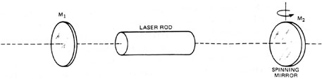
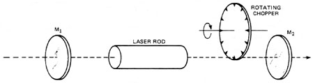
Mechanical Q-Switches Two of the devices in this category are a light chopper and a spinning mirror. See Figures 6 and 7.
Fig. 6
Fig. 7
A light chopper is a spinning disc with a hole in it or a spinning blade (like a fan blade). The chopper is inserted into the optical cavity between the laser rod and the maximum reflectivity mirror. This system provides 100% dynamic loss and 0% insertion loss. A chopper is so slow, however, that it can Q-switch only a fraction of the beam area at a time as it is swept across the aperture. For this reason light chopper Q-switches are not practical or effective. Spinning reflectors are used quite frequently in Q-switched systems where it is not necessary to closely synchronize the output to some other event. Usually the maximum-reflectivity mirror is rotated so that the mirror is tilted out of alignment. The system is Q-switched when the mirror rotates back into alignment (it is in alignment once each revolution). Rotating mirror Q-switches offer 100% dynamic loss and 0% insertion loss. The Q-switch speed can be made fast enough by rotating the mirror at high speed (20,000 to 60,000 rpm) or by various optical schemes to multiply the effect of the rotating element. Switching time is typically a few nanoseconds. In both the chopper and spinning reflector, it is necessary to synchronize the firing of the flashlamps with the position of the spinning element so that the pumping pulse has occurred before the system is Q-switched. Synchronization of the output pulse in mechanical systems is poor. Rotating mirror Q-switches may be used with either pulsed or CW pumped lasers.
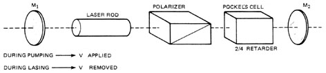
Electro-Optic Q-Switches These devices—see Figure 8—usually require the placing of two elements into the reflecting cavity between the laser rod and the maximum reflecting mirror. These elements are a polarization filter (passive) and a polarization rotator (active). Producing a low cavity feedback with these devices involves rotating the polarization vector of the laser beam inside the cavity so that it cannot pass through the polarization filter. When this polarization rotation is removed, the cavity reflectivity is relatively high and the system will produce a giant pulse. Two of the electro-optic devices used in this application are Kerr cells and Pockel’s cells. Electro-optical Q-switches have high dynamic loss (99%) and relatively high insertion losses (15%) because of the losses in the optical elements. Switching time is fast, typically less than a nanosecond, and synchronization is good. Electro-optical Q-switches are well suited for pulsed systems but cannot be used with CW pumped lasers as their high insertion loss prevents lasing.
Fig. 8
Acousto-Optic Q-Switches This technique involves the use of a transparent element placed in the cavity between the laser rod and the maximum-reflectivity mirror. This transparent device—see Figure 9—when excited with intense, standing, acoustic waves exhibits a diffraction effect on the intracavity laser beam and diffracts part of the beam out of the cavity alignment. This results in a relatively low feedback. When the acoustic wave is removed, the diffraction effect disappears, the cavity is again aligned, and the system emits a giant pulse. Acousto-optic devices have low insertion loss (typically less than 1%) and low dynamic loss (50% maximum). Switching time is slow at 100 ns or greater, and the synchronization is good. These devices are ideally suited for use with CW pumped systems or low-gain pulsed lasers. They cannot be used with most pulse pumped systems because their low dynamic loss will not prevent lasing.
Fig. 9
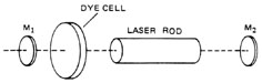
Bleachable-Dye Q-Switches Bleachable dyes are available as thin films on glass substrates or as liquids in glass "windowed" cells. See Figure 10. For Q-switching, a dye cell is placed in the laser cavity between the amplifier and the maximum-reflectivity mirror. The dye absorbs the laser wavelength very strongly at low light intensities presenting a very high cavity loss to the laser and preventing lasing until the amplifier has been pumped to a high gain state. When the fluorescence from the active medium becomes intense enough, the energy that is absorbed by the dye optically pumps the dye material causing it to be "transparent" at the laser wavelength. Now the dye cell is "bleached" and no longer represents a high cavity loss to the laser. The "bleaching" of the dye is the equivalent of Q-switching in the laser, and it can occur in a period less than a nanosecond.
Fig. 10
Bleachable dye Q-switches rate very high in dynamic loss (>99%) and insertion loss (a few percent at most), and their switching time is fast. They have virtually no synchronization at all. Dye cell Q-switches can be used with pulse pumped systems only because a CW pumped laser never produces sufficient fluorescence to bleach the dye.
Summary Q-switching is a method of obtaining high-peak-power, short-duration laser pulses by controlling the loop gain of the optical cavity of the laser. A Q-switch is essentially a very fast shutter located between the active medium and the HR mirror. This shutter is closed during pumping to reduce the loop gain to zero and prevent lasing. Since there is no lasing to deplete the population inversion, energy stored in the active medium and amplifier gain both reach high values. The Q-switch shutter is then opened producing a very high loop gain. The resulting high-intensity standing wave uses most of the energy stored in the laser active medium to produce one giant pulse. A good Q-switch should reduce the loop gain to zero when closed and should introduce no loss in the cavity when opened. It should switch from one condition to the other as fast as possible, and the switching should be synchronized to external events. No single Q-switch rates high in all four of these prime characteristics. The type chosen for any specific application depends on the type of laser used and system output requirements.
1. Explain the basic principles of Q-switching including the following concepts and their relationship to the Q-switching process:
2. In a particular pulse pumped laser the Q-switch opens exactly at the end of the pumping pulse and does not close to terminate the laser pulse. Draw and label diagrams showing the time histories of stored energy, amplifier gain, loop gain, and output power for this system for the time interval from just before the Q-switch opens until fluorescence dies away. 3. Explain the factors which reduce the efficiency of a typical Q-switched laser below that of the same laser without Q-switching. 4. Explain the four most important characteristics of Q-switches. 5. State the Q-switch characteristic that determines pulse duration and peak pulse power and explain the reason for this effect. 6. Explain the characteristic of a laser active medium that makes a good Q-switched laser and why some lasers cannot be Q-switched. 7. List and explain the operation of the four major types of Q-switch. Rate each according to the four characteristics explained in problem 5 and explain the applications of each. 8. State the Q-switch types that cannot be used with the following lasers and explain why in each case:
9. A laser has mirrors with reflectivities R1 = 0.998, R2 = 0.50, a round trip loss of 6% and an amplifier gain of 10. Determine the dynamic loss (double pass) necessary for a Q-switch to prevent lasing in this system. 10. If T is the single-pass transmission of the Q-switch the loop gain of the laser is: GL = Ga2T2R1R2(1 – L) A CW Nd:YAG laser has parameters R1 = 0.998, R2 = 0.94, L = 0.6%, Ga(max) = 1.5. Determine the following:
Pulsed solid-state laser system Q-switch for pulsed solid-state laser Instruction manual for laser Instruction manual for Q-switch Pulsed laser energy meter (calorimeter) Oscilloscope Fast photodiode for pulse shape measurement Oscilloscope camera Safety goggles for laser Beam block
In this laboratory exercise the student will operate a pulsed solid-state laser in the normal pulse mode and the Q-switched mode. In each case the output will be measured and described, and a comparison will be made between the two modes of operation. Students should have completed the laboratory exercise for Module 3-3, "Energy Transfer in Solid-State Lasers," and Module 3-5, "Pulsed Solid-State Laser Systems," before beginning this laboratory. Students should also read all procedures and the Laboratory Report section before beginning. 1. Review the instruction manual for the pulsed solid-state laser before beginning the laboratory. 2. Read the instruction manual for the Q-switch. Identify all parts of the Q-switch. 3. Set up the pulsed solid-state laser for normal mode operation following the instructions in the laser equipment manual. Place the beam block to intercept the output beam. 4. Operate the system according to specified procedures and observe all recommended safety precautions. Safety goggles are required for all personnel during laser operation. 5. Set up the receiver of the laser energy meter to intercept the output beam of the laser. Also arrange the photodiode and oscilloscope to display the time history of the laser pulse. This is essentially the same beam-measuring system used in the pulsed laser experiment of Module 3-3, "Energy Transfer in Solid-State Lasers." 6. Operate the laser and the beam-monitoring system to verify proper operation. 7. Install the oscilloscope camera on the oscilloscope. 8. Operate the laser with several different values of energy stored in the capacitor bank ranging from lasing threshold to maximum system capability. For each input energy setting make a photograph of the time history of the pulse and measure the output pulse energy. Record the input energy to the flashlamp for each shot, and calculate and record the maximum power of the output laser and the efficiency of the laser. 9. Turn off the laser and de-energize the system following all electrical safety precautions. 10. Install the Q-switch in the laser cavity following the procedures outlined in the Q-switch equipment manual. 11. Align the system and bring it into operation in the Q-switched mode following the recommended procedures and observing all safety precautions. 12. Operate the laser in the Q-switched mode with the same values of input energy as used in procedure Step 8. Measure and record the same values called for in that step for Q-switched operation. 13. Operate the laser in the Q-switched mode with the maximum input energy to the flashlamp while varying the delay time between the firing of the flashlamp and the opening of the Q-switch. For each shot measure the pulse duration and pulse energy and calculate the maximum output power. 14. (Optional) Repeat Step 13 with an input energy value halfway between the lasing threshold for Q-switched operation and the maximum input energy. 15. (Optional) Repeat Step 13 with an output coupler of a different reflectivity. 16. Remove the Q-switch and return the laser system to normal pulsed operation. Return all equipment to its original condition and secure the laboratory.
LABORATORY REPORT The laboratory report for this experiment should include all specifications for the laser system, Q-switch, and beam measurement system. All photographs taken and complete data on each shot should be included. Graphs should be prepared showing the following relationships: 1. Output energy versus input energy for normal mode operation. 2. Efficiency versus input energy for normal mode operation. 3. Output energy versus input energy for Q-switched operation. 4. Efficiency versus input energy for Q-switched operation. 5. Output energy versus delay time for Q-switched operation. Also include graphs of any optional data taken in procedure Steps 14 and 15.
Charschan, S.S., editor. Lasers in Industry. Van Nostrand Reinhold Co., 1972. Ready, John F. Industrial Applications of Lasers. New York: Academic Press, 1978. Stepke, E.T. "The Key to Q-Switching," Electro-Optical Systems Design. April, 1972.
|