| This version reflects the comments of the core participants as reviewed and incorporated in accordance with CORD's FIPSE-supported Curriculum Morphing Project. | ||||||||||
MODULE 3-10 Originally, a dye was defined as an organic compound (i.e., one that contains the element carbon) that emitted a brilliant color when exposed to visible light. This color could be imparted to other materials such as cloth, which was then said to be "dyed." Today this definition has been broadened to include hundreds of organic compounds with certain chemical ingredients and behavior in absorbing and emitting light. Thus, for example, dyes may be colorless and may absorb and emit not only in the visible spectrum but also in the ultraviolet and near infrared. Lasing has been observed in a large number of organic dyes dissolved in various solvents such as alcohol and water. The search for new laser dyes and for more efficient means of exciting them is currently an active area of investigation. Dye lasers can be operated in both pulsed and CW modes. In the pulsed mode, they usually are pumped by other lasers (e.g., pulsed-nitrogen gas lasers or frequency-doubled ruby or Nd:YAG) or by various types of flashlamps. In the continuous mode, the output of a CW argon ion laser generally is used as the pumping source. The most useful feature of dye lasers is their tunability; that is, the lasing wavelength for a given dye may be varied over a wide range. Taking advantage of the broad fluorescent linewidths (50-100 nm) available in organic dyes, one uses a wavelength-dispersive optical element such as a diffraction grating or prism in the laser cavity to perform selective tuning. Such tuning can yield extremely narrow linewidths. By use of several dyes, it is possible to continuously tune the laser output over the entire visible spectrum. In fact, recent developments have extended the tunable range into the near ultraviolet at one end of the spectrum and into the near infrared at the other. Organic dye lasers, because they are both tunable and coherent light sources, are becoming increasingly important in spectroscopy, holography, and in biomedical applications. A recent important application of dye lasers involves isotope separation. Here, the laser is used to selectively excite one of several isotopes, thereby inducing the desired isotope to undergo a chemical reaction more readily.
Upon completion of this module, the student should be able to: 1. Draw and label an energy-level diagram for a typical laser dye. Include all transitions that are of importance in dye laser operation. 2. Explain two types of loss arising from triplet states which tend to diminish the large values of small signal gain that can be calculated theoretically. 3. Explain how the problems of triplet absorption are overcome in each of the following dye laser types:
4. Draw and label a diagram of a CW dye laser optical cavity. 5. Explain each of the following tuning mechanisms used with CW dye lasers, and state the linewidth achievable with each:
6. Explain the operation of a ring dye laser, and explain how this makes better use of the active medium of the laser. 7. Explain the operation of a pulsed nitrogen laser. Include a diagram of a typical output pulse indicating pulse duration and peak power and an explanation of why the pulse has this characteristic power and duration. 8. Draw and label a diagram of a dye laser that is pumped by a pulsed nitrogen laser. Explain the operation of this laser and its tuning mechanism. 9. Explain the operation of the electrical energy storage and triggering system of a flashlamp-pumped dye laser. 10. Set up and operate a CW dye laser in the laboratory and measure its output power under specified conditions and as a function of output wavelength.
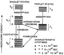
Energy Transfer in Organic Dyes Organic dye molecules are complicated structures composed of a large number of atoms of several species. For example, the chemical formula for the dye known as rhodamine B is: C28H31ClN2O3. This indicates that a molecule of this dye contains carbon (C), hydrogen (H), chlorine (Cl), nitrogen (N), and oxygen (O). The subscript beneath a given symbol denotes the number of atoms that species, e.g., H31 represents 31 hydrogen atoms. The energy-level structure of an organic dye molecule is correspondingly complex. A highly simplified energy-level diagram for a typical dye is shown in Figure 1.
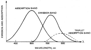
Fig. 1 Two sets of electronic states are displayed—singlets and triplets. Typical energy separation between two singlet or two triplet states is about 10,000-20,000 cm–1. These electronic states are split by vibrational motion of the molecules. The various vibrational sublevels are indicated by heavy horizontal lines in Figure 1. The separation between two neighboring vibrational states is of the order of 1000-2000 cm–1. Rotational molecular motion produces further level splitting (fine structure), indicated in the diagram by the lighter horizontal lines. Two adjacent rotational states are separated by about 10-20 cm–1. The complexity of the dye molecule and the factors leading to line splitting produce broad absorption and emission curves as illustrated in Figure 2.
Fig. 2
Lasing Transitions In Dyes This section traces out the sequence of steps that lead to lasing in a dye laser. Losses due to population of the T1 triplet state and T1 (r) T2 absorption are neglected initially and will be discussed shortly. A dye laser can be considered to be basically a four-level system. Pump light absorbed by dye molecules in the lowest vibrational sublevel A of the S0 singlet ground state produces transitions to one of the upper vibrational levels of S1, as denoted by b in Figure 1. The molecule then undergoes a radiationless decay to the bottom of S1 (b (r) B). The radiationless transition involves a rearrangement of total energy within a system without photon emission. In most instances, the energy is absorbed in increased kinetic energy or motion of the atoms in the system and appears as heat. Lasing may occur between vibrational sublevel B in S1 and an excited sublevel such as "a" within S0, provided a population inversion exists between these two states NB > Na). The B (r) a transition is accompanied by the emission of a photon of wavelength l VA, as shown in Equation 1.
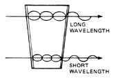
Another radiationless transition, a (r) A, returns the excited molecule to its ground state. Figure 2 shows the broad absorption and fluorescence bands of a typical dye in solution. Notice that the wavelength of light emitted by the dye when it fluoresces is longer than that of the absorped pump light: | EA – Eb | > | EB – Ea | or
so that l Ab < l Ba or finally l Ba > l Ab where the subscripts indicate the B (r) a emission and A (r) b absorption transitions, respectively. Thus, one observes that absorption of light at a given wavelength is re-emitted (fluorescence) at a longer wavelength. This property of organic dyes is used in a number of familiar commercial products such as brightly colored plastic signs and drafting equipment (triangles, protractors, etc.). in detergents, cloth, and paper, certain dyes acts as brightening (whitening) agents by absorbing UV and emitting in the blue portion of the spectrum. The ability to absorb light of short wavelengths and fluoresce or re-emit light of longer wavelengths is one of the most useful properties of organic dyes.
Triplet Absorption in Dyes The small-signal gain per unit length of a typical dye is ~103 cm–1, larger by several orders of magnitude than that of other lasers such as HeNe (10–3 cm–1) or ruby (7 × 10⁻² cm–1). Thus, it would seem an easy task to make a dye laser system work. However, the "troublesome triplets" are a source of difficulties that diminish the advantages of large gain. Figure 1 may be used to illustrate the effects of triplet absorption in dyes. Molecules in the upper lasing level B in S1 may decay to the triplet state T1 by a radiationless transition (S1 (r) T1). This is a forbidden transition in the sense that it is far less probable than a singlet-singlet (S1 (r) S0) transition. Nevertheless, molecules can undergo an "intersystem crossing" (S1 (r) T1) in a time ~50 nsec. T1 is a metastable state with a lifetime of about 10–7 – 10–3 sec for a decay (t1 (r) S0). Hence, molecules can pile up in T1, "stealing" power that could go into lasing via B (r) a transitions. A second problem, that of triplet-triplet (T1 (r) T2) absorption, is even more serious. Figure 2 illustrates the wavelengths at which this absorption (T1 (r) T2) occurs overlap the wavelengths for which lasing is expected. Triplet-triplet absorption can be so strong that the excitation mechanism (CW laser, pulsed laser, or flashlamp) may not have sufficient power to overcome this absorption loss. This can result in no lasing at all or in early termination of lasing. If the population of the triplet state T1 is not limited by some means, it will set the maximum duration of dye laser pulses at about 0.1 m sec. Thus, uncontrolled triplet-triplet absorption would make long-pulse (> 0.1 m sec) and CW operation of a dye laser impossible.
Triplet Quenching Triplet absorption in a flashlamp-excited dye systems is believed to be a major factor in the experimentally observed lack of synchronization between the pump pulse and the laser pulse. That is, the laser pulse terminates before the pump pulse ends. In fact, the laser pulse usually terminates before the intensity of the pump pulse has fallen below the threshold excitation value. This problem will be examined in more detail in a later section. Attempts to construct a CW dye laser led to efforts aimed at controlling the triplet state population. One method often used is to add a second molecule to the dye solution to act as a so-called triplet quenching agent, which promotes T1 (r) S0 transitions. Collisions between quencher and dye molecules are responsible for this de-excitation process. A number of substances have been discovered that have the correct energy-level structure to be effective as triplet quenchers. The one selected depends upon the specific organic dye to be used. For example, a chemical known as cyclooctatetraene (COT) is a good triplet quencher for rhodamine 6G. In CW dye lasers rapid flow of the dye solution is also used to control triplet state population. The dye flows very rapidly through the active gain region where the argon beam is focused. In flowing through this region each dye molecule "sees" a pulse of pumplight. If the dye is circulated fast enough, the individual dye molecule will be irradiated by a light pulse of duration short compared to the triplet decay (T2 (r) S0) time but long with respect to the lifetime of the lasing transition (B (r) a). As an example, suppose the focused spot diameter of the pump beam is 10 microns. If the dye solution is circulated at a speed v = 10 m/sec, then each dye molecule "sees" a light pulse of duration t, where: t = = t = 1 m sec For comparison refer again to Figure 1 for the decay times (T1 (r) S0) and B (r) a) transitions.
CW Pumped Dye Lasers This section examines some design problems posed by a CW pumped dye laser and their solutions. The power density necessary to reach threshold for lasing in a typical organic dye laser is fairly large, ~100 kW/cm2. This value of irradiance generally precludes the use of CW arc lamps or other incoherent excitation sources. The focused beam from commercially available argon lasers, on the other hand, easily can exceed the required threshold power density. In addition, argon lasers have multiline outputs in a range of wavelengths from the near UV to the blue-green, which is convenient for exciting a reasonably large number of dyes. Thus, argon ion lasers are used almost universally for pumping CW dye lasers.
Basic Design Features Figure 3 shows the basic design of an argon-pumped, CW dye laser. The optical cavity of the dye laser consists of three mirrors. The output coupler is a long-radius or flat mirror. Its transmission is typically between 10 and 20 percent. The two high-reflectance mirrors are curved and mounted at the proper separation and alignment to produce a focal point in the beam within the dye jet. Pump light in the form of the argon laser beam is focused into the dye jet at the same point as the dye laser beam.
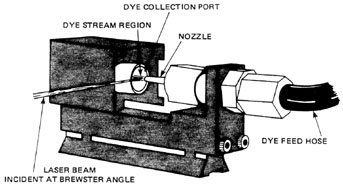
Fig. 3 Figure 4 shows the jet assembly of a CW dye laser. The dye is forced out of a small stainless steel nozzle in a broad, flat stream. The sides of this dye stream are relatively flat over the small area of the focused laser beams and serve as optical surfaces. The jet is oriented at Brewster’s angle to minimize surface reflections. To exceed the threshold power density by a factor of 5, say, the beam from a 1-watt argon laser must be focused down to a very small diameter, ~10-20 m m. However, the focused beam can create a "hot spot" in the dye. Thermal gradients in the dye solution then result in optical inhomogeneities—that is, localized changes in the refractive index of the solution—and subsequent distortion of the output beam.
Fig. 4 Inhomogeneities that arise from thermal distortion can be controlled by rapid flow of the dye solution (~10-20 m/sec) and by use of a dye solvent of which the refractive index is relatively independent of temperature, namely, water. This, in addition to convenience, is the reason that water often is used as the solvent for dyes in CW pumped dye lasers. When water is used as a dye solvent, another problem arises, because most organic dyes do not dissolve readily in water. As a result, the original dye molecules tend to collect or aggregate, forming new molecules called dimers having the same chemical composition but of modified shape and structure. Therefore, these aggregates exhibit different energy levels, resulting in changes in absorption and emission characteristics. Unfortunately, dimers will not lase. This problem can be solved by the addition of a small quantity of de-aggregative or anti-dimerization agent (sometimes called a surface-active agent or surfactant) to the dye solution. A number of commercial detergents have been used as effective anti-dimerization agents, including liquid dishwashing preparations. In certain instances surfactants have the appropriate energy-level structure to act as triplet-quenching agents as well as to prevent the formation of dimers. Strictly speaking, dimers are aggregates of two molecules, while "trimers" are combinations of three molecules, and so on. The general term that describes a large number of molecules in an aggregate is polymers.
Tuning Mechanisms CW dye lasers may be tuned to any wavelength over wide ranges for each dye used. Tuning may be accomplished by several methods. The most common methods will be described here. Figure 5 is a diagram of a birefringent tuning element employed in many CW dye lasers. It consists of three birefringent elements mounted together at Brewster’s angle. Light traveling through these elements is resolved into two components, one polarized along the fast axis and one polarized along the slow axis. These two components travel at different speeds and, thus, become more out-of-phase as they travel through the component. The first element of the birefringent filter is cut to a thickness that results in a retardation of one full wavelength in the visible region for the slow ray. This element is called a full-wave plate. When white light travels through it, one wavelength will actually be retarded by exactly one wavelength. Other wavelengths will be retarded slightly more or less. The wavelength that is retarded by exactly one full wavelength will emerge with its polarization unchanged. All other wavelengths will have an elliptical polarization with a horizontal component. These horizontal components will be reflected from Brewster’s-angle surfaces in the system, producing losses for all wavelengths except the one passed unchanged by the filter.
Fig. 5 Additional filter elements are added for narrower bandwidths. The second element is twice the thickness of the first, and the third element is four times the thickness of the first. Each additional element further reduces the output linewidth. The three-element filter shown in Figure 5 has a typical output bandwidth of 0.025 nm. The birefringent filter is tuned by rotation about an axis perpendicular to its optical surfaces. If the filter is positioned so that its "slow" axis is horizontal, the slow component of the light experiences the greatest retardation. As the filter is rotated, the angle between the slow axis and the direction of travel of the light changes, becoming a minimum when the slow axis lies in a vertical plane. Reduction of this angle also reduces the retardation effect. This allows the slow ray to travel faster as the slow axis becomes more vertical. The result is that different wavelengths experience exactly one full wave retardation at different angular orientations of the filter. A second method of tuning CW dye lasers is the tuning wedge shown in Figure 6. This element is essentially a thin wedged etalon placed in the optical cavity of the dye laser. Tuning is accomplished by moving the tuning wedge back and forth in the cavity to allow the beam to pass through different thicknesses of the etalon.
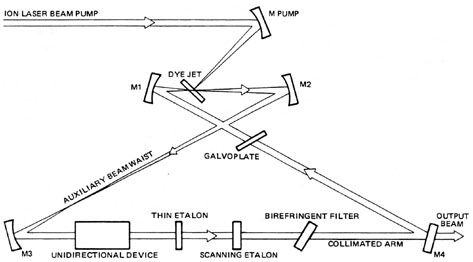
Fig. 6 At any particular point on the etalon, light can pass through it with low loss only if the wavelength of light is correct for forming a standing wave inside the etalon cavity. All other wavelengths experience higher loss due to the etalon and will not lase. (For a discussion of the operation of etalons inside laser cavities refer to Module 3-7, "Argon Ion Laser Systems.") The etalon has only a slight wedge, and sliding it through the cavity will tune the laser over a range slightly greater than the visible spectrum. The tuning wedge is composed of a fused quartz substrate. A reflective coating is deposited on this substrate to form the first partially-reflective surface of the etalon. The next coating element is a wedge-shaped coating of transparent material that forms the wedge-shaped spacer of the etalon. The final coating is another partially-reflective coating. The tuning wedge is mounted at Brewster’s angle to minimize reflection losses. A CW dye laser with either a birefringent filter or a tuning wedge will have several longitudinal cavity modes present in the laser output. For single-mode operation, a thicker etalon for mode selection must be added to the cavity. In some cases, two etalons are added for greater control of the exact laser frequency. Figure 7 shows a ring dye laser designed for what is referred to as "single-frequency" operation. This laser produces an output with a spectral bandwidth of about 5 MHz.
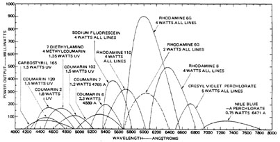
Fig. 7 A ring laser has two advantages over one with a standing wave inside the optical cavity. First, the ring laser has no modes formed by the overall optical cavity and can, thus, lase at any frequency within the laser gain curve. Second, the ring laser makes greater use of the gain volume of the active medium. Standing waves in a typical laser cavity have nodes at which the intensity of the electromagnetic field of the laser light is always zero. No stimulated emission can occur at these points. This results in significant unused gain in the active medium. In a ring laser there is only a traveling wave moving in one direction. This produces a uniform stimulation inside the active medium resulting in the extraction of more of the stored energy. In a typical laser cavity a standing wave is formed by two waves traveling in opposite directions in the cavity. In the ring laser one of these waves is eliminated by an unidirectional device composed of a Faraday rotator and polarizer. This device allows polarized light to pass through in one direction only. The other elements in the optical cavity of the laser in Figure 7 commonly are found in the cavities of both ring dye lasers and those with conventional cavities. The scanning etalon is added to produce a scan of the output laser wavelength over a specified spectral range. The galvoplate is used to change the laser wavelength very slightly by tilting to change the optical length of the cavity slightly. Extremely short laser pulses may be produced with dye lasers by using a mode-locked argon laser as a pumping source and making the dye laser cavity the same length as the argon cavity. This results in synchronous pumping in which the active medium is pumped by a mode-locked argon laser pulse at precisely the right time to produce the maximum gain for a pulse in the dye laser cavity. A variety of laser dyes are available for use throughout the visible spectrum and into the edges of the infrared and ultraviolet regions. Figure 8 shows the output powers and wavelengths of several of the most common dyes used in CW dye lasers.
Fig. 8
Nitrogen-Pumped Dye Lasers Another optical source used for optical pumping of dye lasers is the pulsed nitrogen laser. This section discusses the basic characteristics of nitrogen lasers and the dye lasers used with them.
Nitrogen Lasers Basically, nitrogen lasers are superradiant electrical discharges capable of producing up to several megawatts peak output at high repetition rates (10-500 Hz), with short output pulses of 10-20 nsec duration. A number of different geometries for N2 laser resonators have been employed. A laser channel (~1 meter long) of narrow, rectangular cross section is shown in Figure 9.
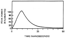
Fig. 9 Nitrogen lasers may be either flowing gas systems, with the gas circulated through the channel by a mechanical pump, or sealed-off systems. Both transverse and longitudinal excitation have been used. The channel illustrated in Figure 9 is excited by electrical discharges transverse to the direction of coherent light output, i.e., the optical axis. Glass plates form the top and bottom of the channel. Long electrodes, sometimes called distributed electrodes, are sandwiched between the plates to form the sides of the resonator. Although nitrogen lasers will operate without cavity mirrors (superradiant laser emission), use of a high-reflectance rear mirror increases the peak power output, decreases beam divergence, and improves beam homogeneity. The ultraviolet output of the laser exits through the glass output window. The beam, like the channel itself, is of rectangular cross section. The energy storage/discharge circuit of an N2 laser generally consists of five basic elements: 1. External high-voltage power supply. 2. Capacitor bank. 3. Fast switch (hydrogen thyratron). 4. Impedance-matching network (transmission network). 5. Laser channel. Energy is stored in a capacitor bank charged by the external power supply. A trigger pulse then is applied to the grid of a hydrogen thyratron used for switching. When the thyratron conducts, the high-voltage pulse travels through the transmission line and appears across the electrodes of the laser channel. This results in a rapid discharge that excites most of the nitrogen molecules in the active medium. The excited nitrogen has an extremely high gain and lases for a few nanoseconds. This produces a high-peak-power pulse, but quickly destroys the population inversion. Figure 10 illustrates a typical nitrogen laser pulse. The spectral output of N2 lasers is concentrated in a number of lines centered around 337.1 nm in the ultraviolet. This is especially convenient for pumping a large number of organic dyes. Nitrogen-pumped dye lasers provide a powerful, tunable, coherent light source for many spectroscopic applications.
Fig. 10
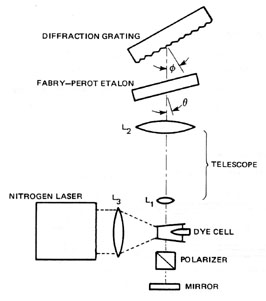
Dye Lasers for Nitrogen Pumping The basic layout of a tunable dye laser side-pumped by a nitrogen laser is shown in Figure 11. Wavelength selection is provided by the diffraction grating, which also acts as the rear (HR) mirror in the cavity. The grating is mounted in a precision laser mount, capable of 0.1 arc-sec resolution. Resolution of the diffraction grating is about 0.008 nm. Addition of the Fabry-Perot etalon increases the resolution such that the resultant laser bandwidth is greatly narrowed down to about 0.0004 nm. Lens L3 focuses the output of the N2 laser onto the dry cell. Lenses L1 and L2 form an inverted astronomical telescope. The telescope expands and collimates the beam emitted by the dye solution to illuminate a large portion of the grating area for good resolution and to prevent the formation of hot spots and resultant damage on the surface of the grating.
Fig. 11 For organic dyes with high gain, a flat quartz window is often used as the output coupler. A broadband multilayer dielectric coated mirror of about 30-50% transmittance is used for dyes having lower gain.
Flashlamp-Pumped Dye Lasers Flashlamp-pumped dye laser systems can excite a larger number of dyes, with higher peak power outputs, and they are of simpler construction, in general, than CW dye lasers. Several types of flashlamp-pumped dye lasers have been devised, differing primarily in flashlamp construction, cavity geometry, and to a lesser extent, in discharge circuitry.
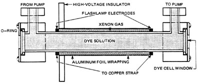
Basic Construction and Operation Figure 12 shows the dye cell of one type of commercially available flashlamp-pumped dye laser. This is a coaxial flashlamp-dye tube design in which the flashlamp is an annular ring surrounding the dye cell for even illumination. Other pulsed dye lasers employ linear flashlamps mounted beside linear dye tubes inside elliptical pumping cavities similar to those used in solid-state lasers.
Fig. 12 The flashlamp must have a short pulse for efficient pumping of the laser dye. This is usually accomplished by operation of the lamp at high voltages and currents. The energy for lamp operation is stored in a high-voltage capacitor. The capacitor is connected to the lamp, and the lamp is connected to ground through a triggered spark gap. Figure 13 shows such a spark gap. It contains three electrodes in a pressurized nitrogen atmosphere. A standard spark plug forms two of these electrodes and is operated by an ignition coil. The third electrode is connected to the lamp terminal. The nitrogen prevents electrical conduction until the gap is triggered.
Fig. 13
The basic operation of the laser is as follows: The capacitor is charged by an external, high-voltage (0-30 kV) d.c. power supply. A trigger pulse is applied to the primary of an auto ignition coil (pulse transformer). A large voltage pulse (10-25 kV) is developed across the secondary terminals of the coil and applied to the trigger portion of the pressurized spark gap, which results in voltage breakdown of the nitrogen gas inside the chamber. This allows the charged capacitor to discharge through the spark gap and, hence, through the flashlamp.
Factors Affecting Pulse Duration As was mentioned in a previous section, in the absence of triplet-quenching (TQ) agents, a dye laser pulse would terminate in about 0.1 m sec. Hence, much attention has been paid to fabrication of flashlamps with fast risetimes. This is reflected in the coaxial flashlamp design shown in Figure 12, which has a risetime of about 300-400 nsec, if a low-inductance (< 20-30 nH) discharge capacitor is used and electrical leads are kept short. The use of COT with rhodamine 6G dye solutions, and other TQ agents for various organic dyes, has led to a relaxation of the requirements for fast-risetime flashlamps. Conventional xenon-filled linear flashlamps with much slower risetimes have been used successfully for dye laser excitation. Nevertheless, a persistent problem associated with flashlamp-pumped dye lasers is the early termination of the laser pulse, usually before the pump pulse has fallen below the level normally required for threshold excitation. Early termination was first attributed to triplet absorption and, in fact, closer synchronization of pump and laser pulses was achieved through the use of heavy concentrations of TQ agents and/or filtering out the UV components in the special output of the flashlamp(s) used. However, in the short-pulse (1-5 m sec) regime, even with the use of TQ agents, fast discharge circuitry, and fast risetime flashlamps, shock waves (with their concomitant pressure variations in the dye solutions and resultant localized changes in the refractive index of the solution) may be a contributing factor in early termination of lasing. Finally, if water is interposed between the flash lamp and dye cell, the remaining lack of synchronization between pump and laser pulses virtually disappears, presumably because of absorption of the IR components of the flashlamp output by the water.
Wavelength Selection in Pulsed Dye Lasers The same methods used for wavelength selection and tuning in CW dye lasers may be used with pulsed dye lasers. Diffraction gratings also may be used as with nitrogen-pumped dye lasers. A light beam incident upon a plane reflection grating will be reflected back along the axis of incidence if the following grating equation is satisfied:
A diffraction grating used in this manner is said to be mounted in the Littrow configuration. The lasing wavelength can thus be varied by rotating the grating about an axis parallel to its grooves since this configuration acts as a tunable reflector. It has high reflectivity at one wavelength at a time, depending upon its angular setting. The metallic coatings used in gratings for commercial dye lasers are usually made of aluminum, gold, or enhanced silver for operation between 400-1100 nm. Such coatings are very fragile. Thus, a beam-expanding telescope is sometimes used between the dye cell and the grating to illuminate most of the surface of the grating to prevent the formation of "hot spots" mentioned earlier.
Summary The active medium of a dye laser consists of an organic dye dissolved in a suitable solvent. The dye molecules are composed of many atoms and have many closely-spaced energy levels. These are broadened to form continuous bands of emission and absorption in the dye. Dye lasers may use any of several dozen dye types, each tunable over its own spectral range. Dye lasers are available in three basic types. CW dye lasers use a dye jet as the active medium. Their excitation mechanisms are the focused beams of argon ion lasers. Wavelength tuning is accomplished with birefringent filters or tuning wedges. Pulsed dye lasers employ a dye cell and are produced in two types. One is pumped by the short-duration pulse of a nitrogen laser. This laser system produces as many as several hundred pulses per second with pulse durations of a few nanoseconds. Tuning is usually accomplished with a diffraction grating. The dye in a flashlamp-pumped dye laser is excited directly by the flashlamp light. These systems are typically capable of a few pulses per second, with pulse duration of several microseconds. They may be tuned by diffraction gratings or birefringent filters. The most important single characteristic of dye lasers is their tunability. This makes them among the most valuable tools available for spectroscopic analysis and photochemistry.
1. Draw and label the energy-level diagram of a typical laser dye. Explain the sequence of energy transitions in the dye molecules that lead to lasing. 2. Refer to diagram of first exercise, and explain the effects of triplet absorption on the laser output. 3. Explain how the problems associated with triplet absorption are reduced in each of the following dye laser types:
4. Draw and label a diagram of each of the following tuning mechanisms used with dye lasers. Explain the operation and application of each, and state the output linewidth achievable from each:
5. Explain the advantages of a ring dye laser over one with a standing wave cavity for spectroscopic applications. 6. Explain the operation of a nitrogen laser. Also describe the output pulse of such a laser and the reasons for its output characteristics. 7. Explain the operation of a flashlamp-pumped dye laser. Include the relationship between the triplet absorption problem and the design of the electrical system of such a laser.
CW dye laser system Manual for dye laser system Argon ion laser system for pumping dye laser Power meter to measure dye laser output power Transmission diffraction grating Meter stick Appropriate dye solution White screen
In this laboratory, the student will operate a CW dye laser system pumped by an argon ion laser. Students will not attempt this laboratory until they have completed the labs of Modules 3-6, "Energy Transfer in Ion Lasers," and 3-7, "Argon Ion Laser Systems." Students will prepare individual reports describing the output characteristics of the dye laser and the procedures used for measuring those characteristics. 1. Read the instruction manual for the dye laser. 2. Turn on the argon laser and verify proper operation. Turn the argon laser off. 3. Follow the instructions in the dye laser manual for establishing dye flow in the system. Check the system for leaks and observe all precautions listed in the manual. 4. Turn the argon laser on and establish dye laser operation. The optical system of the dye laser should be aligned for lasing at the beginning of the laboratory. If lasing does not occur, follow the instructions in the dye laser manual for alignment of the laser cavity and pumping beam. 5. Place the optical power meter to intercept the output beam of the dye laser. Vary the output wavelength and the power of the argon laser, and observe the effects on the output power of the dye laser. 6. Turn off the dye laser and the argon laser following the instructions in the manual. This completes basic familiarization with the dye laser system. 7. Devise a procedure and accomplish the experimental tasks for laboratory exercises assigned by your instructor. The experiments performed and the procedures used will depend on the particular laser used. The following are suggestions:
l =
Use this setup to measure the output wavelength of the dye laser and the optical power meter to measure the power. Draw a curve of output power versus laser wavelength. 8. At the end of the experiment verify proper operation of the dye laser system. Turn off all equipment according to proper procedure and secure the laboratory. 9. Prepare a laboratory report of your experiment.
LABORATORY REPORT The laboratory report for this experiment concerns the output characteristics of the dye laser. The report should include the following items:
O’Shea, Donald C.; Callen, Russell W.; Rhodes, William T. Introduction to Lasers and Applications. Reading, MA: Addison-Wesley Publishing Co., 1977. Ready, John F. Industrial Applications of Lasers. New York: Academic Press, 1978. Technical Bulletin. "CW Dye lasers." Palo Alto, CA: Coherent Radiation, Inc., 1977. Technical Bulletin. "Spectra-Physics CW Dye Lasers." Mountainview, CA: Spectra-Physics Inc., 1979. Technical Bulletin. "Spectra-Physics Single-Frequency Ring Dye Laser." Mountainview, CA: Spectra-Physics, Inc., 1979. > |


 <
<