| This version reflects the comments of the core participants as reviewed and incorporated in accordance with CORD's FIPSE-supported Curriculum Morphing Project. | ||||||||||||
| MODULE 3-4 CW Nd:YAG LASER SYSTEMS Several solid-state laser systems may be operated continuously, but the most common of these is the CW Nd:YAG laser system, operating at 1.06 microns. This module discusses the basic components, general characteristics, and subsystems of these lasers. As the removal of waste heat energy is of the greatest importance in the solid-state laser systems, and in particular in CW systems, much of this module will deal with energy flow in the laser and with cooling considerations. The overall efficiency of a laser is a measure of how much input electrical energy it requires to produce its laser output. CW optically-pumped solid-state lasers are not very efficient devices. Values of efficiency range from 0.1% (one unit of power output for 1000 units in) to 4% (four units out for 100 units in), a typical value being about 1.0%. These low efficiencies mean that practically all of the power that is put into a laser is lost. It is important to know how and where this power is lost so that the losses can be kept as low as possible so that the unused energy (which is practically all converted to heat) can be removed before it degrades the system performance or destroys system components. This module explains the efficiency of a CW Nd:YAG laser by analyzing the power flow and conversion through each component of the system. The purpose of this exercise is to illustrate where power losses can occur, which elements of the laser will become excessively hot during operation, and what methods are useful to cool these components. In the laboratory, the student will align a CW Nd:YAG laser and measure its operating efficiency.
Upon completion of this module, the student should be able to: 1. Draw and label a simplified energy-level diagram of an Nd:YAG laser and explain why effective rod cooling is critical for efficient laser operation. 2. State a brief general description of the following subsystems of Nd:YAG lasers:
3. Explain the terms "quantum efficiency" and "operating efficiency." 4. Draw and label a diagram showing the power flow in an Nd:YAG laser. The diagram must show power flow and all losses from the entry of the electrical power into the laser power supply until the emergence of the output laser beam. All significant losses must be listed. 5. For a CW Nd:YAG laser system, given the output power of the laser, the temperature increase in the cooling water as it passes over the rod, and the input power to the system, make appropriate approximations and calculations to determine the necessary water flow rate and the total temperature rise in the cooling water as it cools the entire system. 6. In the laboratory, align the optical cavity of an Nd:YAG laser. Operate the laser at a variety of cooling temperatures, and measure its efficiency.
Components of a CW Nd:YAG Laser CW Nd:YAG lasers are available in output from a few milliwatts to as high as a kilowatt in power. Although they vary considerably in size and complexity of design, all have the same basic elements shown in Figure 1. The active medium is an Nd:YAG laser rod. It is optically pumped by a continuous-pumping lamp and is placed between two external mirrors that form the optical cavity for the laser beam. This section discusses each of the basic subsystems of such a laser.
Fig. 1
Laser Rod The basic characteristics of Nd:YAG and laser rods made of this material are presented in Module 3-3, "Energy Transfer in Solid-State Lasers." The rods used for CW operation are usually from one to four millimeters in diameter and have lengths from one inch to about six inches. Smaller-diameter rods are preferred because they present fewer cooling problems than larger rods. The rod ends are usually antireflection coated from the Nd:YAG wave-length of 1.06 microns. The rod is mounted inside a quartz or glass water jacket. Cooling is provided by water flow directly across the rod surface. The rod ends are held in place and sealed by O-rings recessed in the ends of the rod holders to protect them from the pump lamp light.
Optical Pumping System The optical pumping lamp for CW Nd:YAG lasers is either a quartz-halogen lamp or a krypton arc lamp. The characteristics of these lamps are discussed in Module 3-3. If a quartz-halogen lamp is used, cooling is applied to the lamp ends. Krypton arc lamps are generally enclosed in their own water jackets and have water cooling for the lamp cathode. The lamps are usually mounted with the rod inside an elliptical pumping cavity, which is water cooled and in some models may be flooded. The elliptical surface may be coated with one of several materials. Gold is the best reflector for the pump light, but it is not that durable. Chromium plating is often used as a compromise between reflectivity and aging. Both single and double elliptical cavities are common. Power supplies for both quartz-halogen and krypton arc lamps are discussed in Module 3-1, "Power Sources for CW Lasers."
Optical Cavity The optical cavity of the Nd:YAG laser usually consists of two mirrors mounted separately from the laser rod. Several cavity configurations may be used, but all employ at least one spherical mirror. Both long radius and long radius hemispherical cavities are commonly employed. In some systems, shaping of the beam within the cavity is desirable, and two mirrors with different radii of curvature are used. The HR mirror has a reflectivity of about 99.9% and the output coupler transmission varies from less than one percent on small lasers to about eight percent on larger ones. The optical cavities of Nd:YAG lasers are often equipped with an adjustable or interchangeable aperture for selection of multimode or TEM00 mode operation.
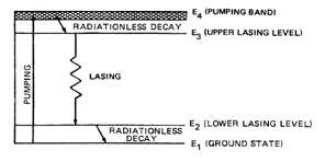
Cooling System The cooling system is one of the most critical subsystems in the laser. Smaller lasers may use open-loop cooling systems with tap water flowing across the rod. In such cases, the water should be filtered to remove any contamination or impurities. Larger systems use closed-loop cooling with water or a water-glycol solution. The coolant is usually refrigerated, but a water-to-water or water-to-air heat exchanger may also be employed. The cooling fluid circuit begins with the laser rod for maximum rod cooling. The water then flows across the lamps and the laser cavity. A flow switch is generally included to turn off the lamp power if the water flow is interrupted. Loss of cooling will quickly destroy seals, lamps, and the laser rod itself. Figure 2 shows the energy-level diagram of an Nd:YAG laser.
Fig. 2 Lasing in ND:YAG is dependent upon rapid transitions from the lower lasing level to the ground state by radiationless transitions. These transitions occur at a high rate only if the rod temperature is low. Thus, lasting efficiency depends very highly upon the cooling efficiency. Lasting action will cease entirely before the rod temperature is high enough to damage the rod, and lower operating temperature could result in higher output powers. If the cooling water is too cold, however, condensation will form on the laser head and optical surfaces. This can lead to problems and should be avoided. Cooling systems are generally operated at temperatures just above the threshold of this effect.
Energy Losses in Nd:Yag Lasers The quantum efficiency of a laser is the energy of an output photon divided by the input energy necessary to produce that photon, assuming that the rest of the system is perfectly efficient. In the case of Nd:YAG, this is the energy of a laser output photon divided by the energy of an input pump light photon. As illustrated by Figure 2, the quantum efficiency of Nd:YAG is high at about 80%. The operating efficiency, h , of a CW laser is given by Equation 1.
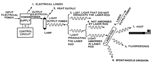
The output power is measured with an optical power meter or calorimeter, and the input power is measured with an electrical wattmeter. The operating efficiency in most Nd:YAG lasers is between one and two percent. Since "CW laser" means that the laser is operating "continuously" over some time period, it is assumed that any CW laser studied or analyzed has been operating a sufficient length of time to have reached "equilibrium conditions." This means that all of the inputs and outputs and temperatures have reached a constant, "steady-state" level and are not changing significantly. Under these conditions, for any fixed period of time, energy is proportional to power. This module discusses only lasers operating in the continuous, equilibrium state, and any statements about energy input, output, or losses also apply to power input, output, or losses. Any component in a CW laser system that remains at a constant temperature and power level, whether it is the power supply, the lamp, the reflector or the laser rod, has the same amount of energy (or power) leaving it as it does entering it. The power can change its form (electrical, optical, or heat) but its value does not change under steady-state conditions. This section traces power through a CW Nd:YAG laser system during steady-state operation and accounts for all the important power losses. Figure 3 is a schematic diagram of this energy flow showing all major losses.
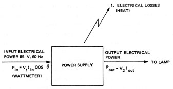
Fig. 3 1. Electrical Power Supply Losses (See Figure 4): These loses are the result of resistance losses in leads, connections, transformers, variacs, meters, and lights; and inefficiencies in other electrical components of the power supply such as hysteresis, capacitor leakage, filters, etc. The amount of these losses can roughly be determined by subtracting output power from input power. These quantities can often be obtained on commercial equipment from the manufacturer’s specification sheet or the equipment instruction manual. As a "rule of thumb," dc power supplies in the kilowatt power sizes are about 80% efficient.
Fig. 4 2. Heat Output from the Lamp (Figure 5): If the lamp has an incandescent filament (usually tungsten), the source of light is the radiation from the hot filament. This is a very close approximation to a "blackbody radiator" and its output has a broad, continuous wavelength spectrum ranging all the way from light waves down into heat waves. These lamps are usually less than 30% efficient for pumping neodymium lasers. If the lamp is a gas tube (usually xenon or krypton gas), the heat output comes from three sources: (a) heating of the electrodes from the high current density and electron bombardment in the ionized gas; (b) heat generated within the gas; (c) absorption of the light by the lamp envelope (glass or quartz tubing). Efficiencies of CW gas arc lamps are about 30%. Most CW lamps must be cooled by forced air or circulating water.
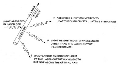
Fig. 5 3. Light from the Lamp that Does not Irradiate the Laser Rod (Figure 5): Light from the lamp is emitted in all directions and usually requires a reflector around the lamp and laser rod to focus or redirect the light onto the laser rod. Although the reflectors are usually highly polished metal or magnesium oxide and have a high reflectivity (90%), many rays from the lamp will not reach the rod in a single reflection. (They may require five or six reflections, or they may never reach the rod.) However, a good reflector should be at least 80% efficient. 4. Light Output Power Irradiating the Laser Rod but not Being Absorbed (Figure 5): This can be caused by two phenomena. First, it can be shown that, if a light ray from the lamp strikes the surface of the laser rod at a low or "grazing" angle, it will be mostly reflected and will not significantly enter the laser material. Second, characteristics of the laser material are such that it will absorb only certain wavelength regions of light, as was discussed previously under the absorption spectrum of laser materials. 5. Laser Rod Power Losses (Figure 6): The last three losses all pertain to physical mechanisms that take place at the atomic level in the laser material. The phenomena have all been explained in earlier modules on the emission of light. It is sufficient at this point to say that useful laser output must come from the laser material in the form of stimulated emission of light at the proper wavelength and along the optical axis of the laser.
Fig. 6 Cooling System Calculations The cooling system of the laser must remove most of the waste heat from the entire system. Only a small fraction of the input energy appears in the laser output. Other relatively small amounts of energy escape as fluorescence passing through the rod ends and as radiative or convective heating of the laser environment. The cooling system must be capable of removing waste heat continuously at the maximum input power level. One way to design a cooling system for a CW YAG laser is to estimate the amount of radiant power being absorbed by the laser rod, set the desired limit on allowable temperature rise in the water after cooling the rod, and calculate the flow rate of the coolant (water). This is best illustrated by Example A.
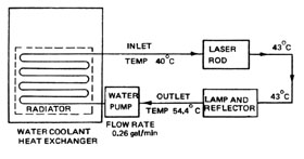
The absolute equilibrium input temperature of the coolant water will be determined by characteristics of the cooling system and the ambient conditions. A typical coolant temperature might be 40� C. Using this value and those calculated in Example A, a coolant flow diagram can be drawn as shown in Figure 7.
Fig. 7 Nd:YAG Laser Accessories Nd:YAG lasers are operated in the CW output mode at 1.06 microns for many applications, but other operational modes are also common. Perhaps the most common of these is Q-switching the optical cavity while the active medium is continuously pumped. Principles of Q-switching are discussed in detail in Module 3-12, "Laser Q-Switching—Giant Pulses." At this point, it is necessary to note only that a Q-switch is a kind of shutter that blocks lasing momentarily to allow a large population invgrsion (and high gain) to develop. The shutter is then opened, resulting in a short, powerful laser pulse. The Q-switch most frequently used with CW Nd:YAG lasers is an acousto-optical device that introduces little insertion loss in the system and may be operated at pulse repetition rates of 50,000 pps. Operating a CW pumped, repetitively Q-switched Nd:YAG laser at 20,000 pps generally results in a peak pulse power that is around 500 times the CW output power of the same laser. The average power in this repetitively pulsed mode may be as much as 90% of the CW output power. Pulse durations are typically a few tenths of a microsecond. Another possible modification for CW Nd:YAG lasers is the addition of a frequency-doubling crystal inside the laser cavity. The most common frequency-doubling crystals for Nd:YAG are lithium niobate (LiNb03 ) and barium sodium niobate (Ba2 NaNb5 01 5 ). The crystals are cut at precise angles and are contained in a temperature-controlling oven for proper phase matching inside the laser cavity. Cavity mirrors are both highly reflective at 1.06 m . The HR mirror is also highly reflective at 533 nm, and the output coupler is highly transmitting at this doubled frequency. Thus, the Nd:YAG laser light is converted to 533-nm green light, which forms the output beam.
Summary A CW Nd:YAG laser consists of a solid-state laser rod designed and mounted for high cooling efficiency, a continuous optical pumping lamp with a suitable power supply, an optical system for focusing the pump lamp light into the rod, a low-loss optical cavity, and a cooling system for removal of waste heat energy. Acousto-optical Q-switches and frequency doublers may also be included in CW Nd:YAG laser systems. A most critical subsystem of the laser is the cooling system. Without adequate cooling, the laser seals, pumping cavity, lamps, and the rod itself would be quickly destroyed by overheating. Lasing in Nd:YAG is most efficient when the temperature is lowest. Thus, cooling systems are designed to produce the lowest practical system operating temperature.
1. Draw a simplified energy-level diagram of Nd:YAG and use it to explain why lasing is more efficient at lower rod temperatures. 2. Explain the terms "quantum efficiency" and "operating efficiency." 3. Draw and label a diagram showing power flow in an Nd:YAG laser. 4. Use the above diagram to explain power losses in the laser. 5. Explain the term "frequency doubling" and what is required to produce a frequency-doubled Nd:YAG laser. 6. An Nd:YAG laser has an input power of 2000 watts of electrical power and uses a krypton arc lamp. Output power of the laser is 3.5 W. The cooling water experiences a temperature rise of 4� C in passing over the rod. Make appropriate approximations and calculations to determine the water flow rate and total temperature rise in the cooling water.
CW Nd:YAG laser system with removable mirrors and refrigerated closed-loop water cooling system Equipment manual for laser Safety goggles Power meter for measuring laser output power Nd:YAG beam viewing screen with light source HeNE laser Adjustable table to HeNe laser Electronic contact thermometer Electrical wattmeter to measure laser electrical input power
The laboratory for this module consists of alignment procedures and temperature and efficiency measurements for a CW Nd:YAG lasgr system. This is the same laser system operated previously in the laboratory of Module 3-3, "Energy Transfer in Solid-State Lasers." Students should not attempt this laboratory until they have satisfactorily completed the exercises in Module 3-3. Students should read all laboratory procedures and the laser equipment manual before beginning the laboratory. Proper safety precautions as outlined in the equipment manual must be observed throughout the laboratory. Safety goggles must be worn by all persons present when the laser is in operation. 1. Read the equipment manual for the Nd:YAG laser. 2. Place the viewing screen to intercept the output laser beam, and operate the laser according to instructions in the equipment manual. Observe the beam as displayed on the screen. 3. Reduce laser input power until no laser output is present, and replace the screen with the detector head of the optical power meter. Align the power meter head to intercept the entire laser beam at a distance of about one meter from the laser output aperture. 4. Verify power meter operation. 5. Turn off and de-energize the laser system. Place the electrical wattmeter on the input of the laser power supply to measure electrical input power. 6. Bring the laser system into operation. Measure and record input electrical energy and output optical energy of the laser at several points over its output power range. 7. Allow the laser to operate for five minutes at its maximum output power so that all temperatures in the system will stabilize. 8. Use the electrical contact thermometer to measure temperatures of the following points in the cooling system:
These measurements should be made as directed by the laboratory instructor in accordance with electrical safety procedures necessary for individual laser systems. 9. Turn off the laser power supply and measure the volume flow rate of the cooling system. If no flowmeter is provided, this may be accomplished by catching return water from the cooling system in a calibrated container and measuring the time necessary to fill the container. 10. Calculate heat gain of the water as it flows across the rod, additional heat gain from other components of the laser head, and total heat load on the cooling system. 11. Change the temperature setting of the laser cooling system to a lower setting than that used in the above procedure. Bring the laser into operation and allow it to operate for five minutes. Repeat Step 6 at this temperature setting of the cooling system. 12. Repeat the above procedure a third time for an input water temperature above the original temperature. 13. Turn off the laser and remove the cavity mirrors, following instructions in the equipment manual. 14. Place the HeNe laser on the adjustable table about a meter from the output aperture of the Nd:YAG laser. Align the HeNe beam to pass down the center of the Nd:YAG rod. The beam should be adjusted so it enters the center of the rod and the reflection from the rod end is directed back into the HeNE laser output aperture. Neither laser should be moved from the alignment position until YAG laser operation is confirmed. 15. Place the HR mirror on the Nd:YAG laser in its mount, and align it to return the reflected HeNe beam into the HeNe output aperture. This aligns the mirror with the rod axis. This alignment should not be adjusted further until lasing is achieved. 16. Place the Nd:YAG output coupler in its mount and align the reflection from it to enter the HeNe output aperture. 17. Place the Nd:YAG beam display screen between the two lasers to display the YAG laser beam. Turn on the Nd:YAG laser and observe the screen. 18. Lasing may occur immediately, but this is usually not the case due to a wedge in the output coupler that results in a slight misalignment. Small adjustments or "rocking" motions of the output mirror should be made until lasing is observed. 19. When lasing is achieved, adjust the output coupler to produce the best beam shape as observed on the beam display screen. 20. Place the power meter in the beam and fine-adjust both mirrors to achieve maximum output power. 21. Turn off the laser, return all equipment to its original condition, and secure the lab. 22. Prepare a laboratory report evaluating effects of the cooling system on laser output power and efficiency. The report should include all pertinent data arranged in a clear manner and a description of how data was obtained. The report should also contain graphs of laser output power and laser operating efficiencies as a function of laser input power for three different cooling system temperatures. 
Harry, John E. Industrial Lasers and Their Applications. Maidenhead-Berkshire, England: McGraw-Hill Book Company (UK) Limited, 1974. Lengyel, Bela A. Introduction to Laser Physics. New York: John Wiley and Sons, Inc., 1966. O’Shea, Donald C.; Callen, Russell W.; Rhodes, William T. Introduction to Lasers and Their Applications. Reading, MA: Addison-Wesley Publishing Co., 1977. Ready, John F. Industrial Applications of Lasers. New York: Academic Press, 1978. Weast, Robert C. Handbook of Lasers. Chapter 2. Cleveland, OH: Chemical Rubber Company Press, 1971. |
||||||||||||


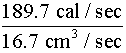
 = 189.7
cal/sec
= 189.7
cal/sec =
=