| This version reflects the comments of the core participants as reviewed and incorporated in accordance with CORD's FIPSE-supported Curriculum Morphing Project. |
| MODULE 3-3 ENERGY TRANSFER IN SOLID-STATE LASERS Lasers can be classified according to the type of material used for the active (amplifying) medium and the temporal (time) characteristics of the output. In a "solid-state laser" the active medium is a solid material instead of a gas or a liquid. All solid-state lasers are optically pumped, which means that excitation of the active medium is achieved by the absorption of light. Solid-state laser operation may be either continuous wave or pulsed. The initials "CW" stand for the term "continuous wave," and indicate that the output of the laser is continuous during the time of operation, and that there is very little fluctuation or flicker in the output power level. If the laser is to be continuous, the optical pumping light source also must be continuous. These high-intensity, continuous light sources produce a large amount of energy in the form of both light and heat that is not used for pumping the laser rod. This heat within the laser head requires that a cooling system be used on the laser for it to operate efficiently and avoid damage to the laser elements. The term "pulsed laser" indicates that, during one cycle of operation, the laser has an output that lasts for only a short period of time (usually less than 5 milliseconds). The duration of the output is dependent upon the intensity and the temporal characteristics of the pumping source and active medium. The energy transfer mechanisms at work in solid-state lasers and the basic characteristics of the three most common solid-state lasers are discussed in this module. Topics include characteristics of solid-state laser materials, optical pumping sources, spectral matching, and pumping cavity configuration. Modules 3-4, "Nd:YAG Laser Systems," and 3-5, "Pulsed Solid-State Laser Systems," discuss these lasers in greater detail. In the laboratory the student will operate a pulsed solid-state laser and a CW solid-state laser and measure the output characteristics of both.
Upon completion of this module, the student should be able to: 1. List the three most common solid-state laser materials, and state the chemical formula for the crystalline materials and the doping levels for each material. 2. Draw diagrams describing the absorption spectra of ruby and Nd:YAG. 3. Discuss differences in the absorption spectra of Nd:YAG and Nd:glass and the reasons for the differences. 4. Explain factors that limit ruby and Nd:glass lasers to pulsed operation and the salient material characteristics allowing CW operation of Nd:YAG lasers. 5. Draw, label, and explain simplified energy-level diagrams for three- and four-level lasers. 6. Explain how laser rods are manufactured and the reasons for the size limitations for each material type. 7. Explain the term "spectral matching" and its importance in solid-state lasers. 8. Sketch the output spectra of the following types of light sources:
9. Compare the output capabilities of ruby, Nd:YAG, and Nd:glass lasers operated in the pulsed mode. 10. Draw and label diagrams showing the following pumping geometries:
11. Explain which pump sources may be used with the following laser types and which is the most efficient for each:
12. Use the procedures and materials listed in this module to operate a CW Nd:YAG laser and a pulsed solid-state laser in the laboratory. Measure the output characteristics of each and observe the effects of the focused laser beam on irradiation samples.
Characteristics of Solid-State Laser Materials The active medium of a solid-state laser consists of a cylindrical rod and of some nonconducting material that is transparent to the laser wavelength and contains a small amount of an impurity ion that serves as an emitter of laser light. In the majority of simple laser systems, the ends of the laser rod are polished flat and parallel, and mirrors are aligned to an optical axis along the center of the rod. Excitation is by means of optical pumping by a flashlamp. Many solid-state laser materials have been developed and tested using a variety of crystals and glasses as host materials and metallic ions as the active impurity. The most important of these materials are ruby, neodymium in glass, and neodymium in yttrium aluminum garnet (YAG). This section discusses the characteristics of each of these materials. Ruby Ruby is chromium-doped sapphire. Sapphire is a water-white, clear crystal composed of aluminum and oxygen atoms (Al2O3). The chemical formula for ruby is Al2O3:Cr+++. The notation "Cr+++" indicates that the chromium atom is in a triply-ionized state inside the crystal host. Synthetic rubies, made for jewelry, are usually doped with 0.5% chromium oxide (by weight), producing a very deep red material. The chromium doping in red ruby is much too high for laser crystals. Experience has shown that optimum laser operation occurs with "pink" ruby where the doping is 0.03%-0.05% chromium oxide, depending upon the manner in which the ruby is to be pumped and the type of operation desired. Some of the more important physical properties of ruby are:
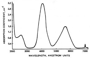
The red (or pink) color of ruby is due to the light absorption of the "impurity" chromium atoms. A simplified absorption spectrum of ruby is shown in Figure 1. The two broad absorption regions centered on 400 nm and 550 nm are both used for optical pumping of the ruby. Thus most of the useful pump light for a ruby rod lies in the blue-green portion of the visible spectrum.
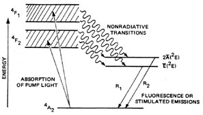
Fig. 1 Figure 2 shows the energy-level diagram for a ruby laser. Many other levels are present in ruby. Only those important to laser operation are shown. (Energy levels in this diagram are labeled with spectroscopic notation. The exact meaning of the notation is unimportant in understanding the material in this course.) The state labeled 4A2 is the ground state of the ruby. The two transitions from this state to the 4F1 and 4F2 states are the two strong absorption bands in the ruby absorption spectrum (shown in Figure 1). Chromium atoms remain in these states for only about 10–8 seconds before experiencing a spontaneous nonradiative transition to one of the two lower energy states indicated in the diagram. Lasing occurs on the transition labeled R1 in the diagram at a wavelength of 694.3 nm. The R2 transition may also be made to lase under certain conditions with a wavelength of 692.7 nm, but it does not normally contribute greatly to laser output. The fluorescent lifetime of the upper lasing state is the average time an atom remains in that state before dropping to a lower state by spontaneous emission. For ruby this is about 3 msec, which is among the longest durations for any laser.
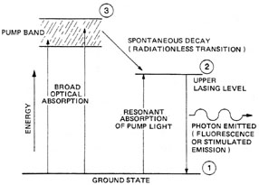
Fig. 2 Since the laser transition in ruby terminates at the ground state, it may be considered to be a three-level system. Figure 3 shows a simplified energy-level diagram for a three-level laser. Atoms are pumped from the ground state to the pump band by the absorption of optical energy from a flashlamp. The atoms decay rapidly to the upper lasing level where the population builds up because of the long lifetime. For lasing to occur, a population inversion must exist between this level and the ground state. Because most atoms are initially in the ground state, intense pumping is required to empty the ground state and establish the population inversion. The high pump rates necessary to maintain a population inversion in ruby add more energy to the rod than it can dissipate if applied on a continuous basis. Thus, ruby lasers are operated in the pulsed mode only. CW ruby lasers have been built, but they are of little significance.
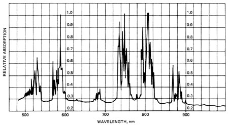
Fig. 3 Another characteristic of ruby lasers is the polarized output. The ruby crystal has a symmetry axis called the c axis. In most ruby rods this axis is perpendicular to the optical axis of the rod. The apparent darkness of such a rod will vary as the rod is rotated. When the rod appears the darkest, the direction of observation is along the c axis. This represents the greatest absorption of the ruby. Stimulated emission of a ruby laser is preferentially polarized perpendicular to the optical axis. Rubies are usually cylindrical with the centerline axis 60� or 90� to the optical axis. Neodymium:YAG The most frequently employed solid-state laser material is yttrium aluminum garnet doped with neodymium ions to a concentration as high as 5%. The chemical formula for YAG is Y3Al5O12. YAG is a hard clear crystal with a thermal conductivity about ten times that of glass. It has a high melting point and is strong and durable. Pure YAG is a clear crystal similar in appearance to pure sapphire. The addition of the rare earth element neodymium results in a purple tint to the Nd:YAG laser rod. The neodymium atoms are in a triply-ionized state inside the crystal, just as chromium atoms are in a ruby laser rod. Figure 4 is the absorption spectrum of Nd:YAG. Rather than broad, continuous bands as in a ruby, the YAG absorption lines form sharp spikes within closely packed bands. The two important pumping bands in Nd:YAG lasers are in the regions of 730-760 nm and 790-820 nm. Since both of these bands are in the near infrared, these wavelengths are the most desirable for optical pumping of YAG lasers. Optical energy also may be absorbed at the shorter wavelength bands, but this is inefficient and the presence of too much light in the ultraviolet region will damage the rod by increasing its absorption, leading to overheating and loss of efficiency.
Fig. 4 Figure 5 is an energy-level diagram of Nd:YAG. Neodymium atoms in the ground state absorb photons and are raised in energy to one of the pump bands. The states in these bands have lifetimes on the order of 10–8 seconds, and the atoms quickly drop to the upper lasing level by radiationless transitions. The upper lasing level, 4F3/2, has a fluorescent lifetime of about 0.3 msec. A population inversion develops and lasing occurs, with the atoms dropping to the lower lasing level. This level is very close to the ground state, and excited atoms rapidly return to the ground state by another radiationless transition.
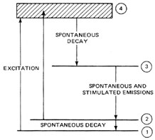
Fig. 5 The energy associated with radiationless transitions as well as the thermal and other optical cavity energy absorbed by the rod all add to the internal energy of the laser rod. If the rod temperature is too high, the lower lasing level is thermally populated by atoms from the ground state, and the rate of transition from the lower lasing level to the ground state is greatly reduced. This destroys the population inversion and quenches lasing. Thus, cooling to maintain a proper temperature is very important in Nd:YAG lasers. Water cooling of the rod combined with the high thermal conductivity of YAG provides a cooling effect sufficient that small-diameter Nd:YAG laser rods may be operated in the CW mode. YAG is the only widely used solid-state laser material capable of CW operation, although other CW solid-state lasers are under development. Nd:YAG is a four-level laser. Figure 6 is a simplified energy-level diagram of a four-level laser. In this case, the lower laser level is an excited state above the ground state. Since most atoms are in the ground state, which is not the lower lasing level, relatively weak pumping is required to create a population inversion. Only a few percent of the atoms must be removed from the ground state and placed in the upper lasing level for a population inversion to be established, provided that rapid decay from the lower lasing level to the ground state prevents a population buildup that would quench lasing. The combination of high thermal conductivity and a four-level structure makes the Nd:YAG an ideal CW solid-state laser and results in higher efficiency in the pulsed mode than for ruby.
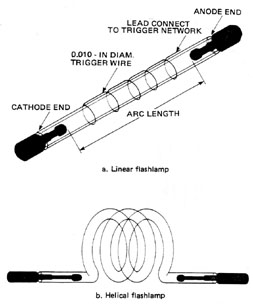
Fig. 6 Neodymium:Glass Neodymium atoms are also used as the active elements in Nd:glass lasers. The doping level is usually 1% or less. The absorption spectrum and energy-level diagrams of Nd:glass are similar to those of Nd:YAG, but the glass absorption peaks are much broader and less distinct. The reason for this is that glass is not a crystalline structure as is YAG. Glass is a supercooled fluid and has a random amorphous structure. Neodymium ions in a YAG crystal all have the same spacing from neighboring atoms and very similar environments. In glass the atomic distances and distribution are random, and each ion has a different environment. This causes the energy levels of different ions to shift differently, broadening all the absorption and emission lines considerably. This also results in a somewhat longer lifetime for the upper lasing level. This means that Nd:glass has a higher efficiency than Nd:YAG in the pulsed mode and a broader output linewidth. As noted earlier, glass has a much lower thermal conductivity than YAG. This means that the waste heat is retained in the lasing material longer, resulting in a greater temperature rise. For this reason the transition from the lower lasing level to the ground state in Nd:glass occurs much more slowly as the laser temperature rises during operation. This quickly quenches lasing and requires that Nd:glass lasers operate in the pulsed mode only. Laser Rod Construction Crystalline laser rods (ruby and Nd:YAG) are grown in crystal ovens by a process that produces single crystals of large size called boules. The size of the rod that can be manufactured depends on the size and quality of boule that can be produced. Ruby crystals may be grown in large sizes with uniform optical qualities, and rods as large as an inch in diameter and 16 inches long may be produced. An increase in rod diameter beyond this is not practical as absorption in the outer layers will prevent adequate pumping at the rod center. Most ruby rods are a half-inch in diameter and have lengths from three to six inches. Nd:YAG rods are made by the same process, but Nd:YAG boules always have an inhomogeneous region in the center. This requires that the laser rods be cut from an annulus of the boule to realize optimum optical properties. For this reason Nd:YAG rods cannot be manufactured in sizes above a half-inch in diameter and six inches long. The largest Nd:YAG rods commercially available are in the range of one-quarter inch in diameter by six inches long. Small rods for low-power CW lasers may be only a millimeter in diameter and less than two inches long. Nd:glass is produced by molding liquid glass into the desired shape and size, and then grinding and polishing the result as with the crystalline laser rods. There are no limitations on the size of glass laser rods. However, a rod diameter of much over two inches will result in little pumping at the rod center. Typical Nd:glass laser rods are a half-inch in diameter and may have any length from a few inches to three feet. Glass is also shaped into disks with a thickness of about two inches and diameters as large as 50 cm. These are pumped by light falling on the face of the disk and are used as amplifiers in oscillator-amplifier laser systems. Each material is shaped into a cylinder. The outer surface of the cylinder may be polished smooth or may be left in a slightly roughened state. In the case of disks, they usually have an absorbing or nonreflecting surface attached to avoid internal reflections which would lead to parasitic losses. For rods the ends are ground and polished to produce optical surfaces and may have antireflective or reflective coatings applied. Comparison of Solid-State Laser Characteristics Differences in the rod sizes and properties result in different characteristics for different solid-state lasers. This section discusses some of the differences that are often important in selecting a laser for a particular application. Because only Nd:YAG lasers may be operated CW, the comparisons here will be for pulsed operation. Pulsed Nd:YAG laser systems produce pulses with a maximum energy of about 50 joules. The pulse repetition rate may be chosen as any desired rate up to continuous operation. Some Nd:YAG industrial lasers will produce 20 joules per pulse at 20 pulses per second, and several hundred pulses per second at the same average power. High pulse-rate capability and dependability are the strong points of pulsed Nd:YAG lasers. Nd:glass lasers typically can be pulsed only once every few seconds, but the larger rods can deliver pulse energies of several hundred joules for relatively small systems and kilojoules for larger ones. They are the most efficient solid-state lasers, and the least expensive. This makes glass popular where high-energy pulses are required. Ruby lasers can be pulsed at rates as high as slightly over one shot per second with pulse energies greater than those of YAG but less than for an equivalent glass system. They are the least efficient solid-state lasers and their popularity is dropping steadily, although many systems are still in use. The development of additional solid-state laser materials is under way by several organizations, and new types of solid-state lasers probably will be forthcoming in the near future, such as alexandrite which is a tunable laser in the near infrared. Optical Pumping of Solid-State Lasers Excitation in solid-state lasers is accomplished by the absorption of light in the laser rod. This light is produced by a pumping lamp located near the laser rod. Efficient optical pumping requires good spectral matching of the output spectrum of the pump lamp with the absorption spectrum of the laser rod. Any light emitted by the lamp at the wavelength that is not absorbed by the rod is wasted energy. Three types of pump lamps commonly used with solid-state lasers are discussed below. Flashlamps Flashlamps are pulsed optical pumping sources used with pulsed solid-state lasers. A drawing of a linear flashlamp is shown in Figure 7a. The distance between the electrodes, referred to as the "arc length" of this lamp, is generally chosen to be about the same as the laser rod length. The "bore" of the flashlamp (the inside diameter of the quartz tubing or "envelope") is usually the same as the diameter of the laser rod. The choice of the dimensions will make the arc inside the lamp the same size as the laser rod. The lamp and rod are placed inside a reflecting housing with their axes parallel. Specific configurations of the reflector housing are discussed later in this module.
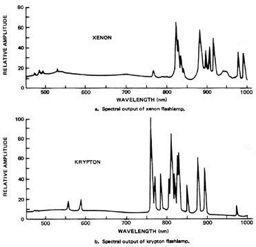
Fig. 7 Flashlamps for pumping pulsed lasers can also be configured using a long quartz tubing coiled into a helix as shown in Figure 7b. The best helical lamps for pumping lasers are made with relatively large quartz tubing, where the inside diameter of the helix is as small as possible and the helix is wound as tightly as possible. The system is operated with the laser rod inside the helix of the lamp and a diffuse, cylindrical reflector outside the lamp (very close). Figure 8 shows the output spectrum of two types of flashlamps. The krypton flashlamp produces most of its output light in the infrared region of the absorption bands of Nd:YAG and Nd:glass. Thus, it is the best spectral match for these laser materials. Krypton flashlamps are not widely used because of their cost. They are far more expensive than xenon lamps, and the xenon lamps also have sufficient output in the desired spectral region. Their lower efficiency is usually acceptable.
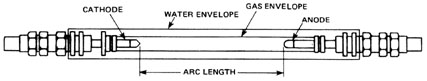
Fig. 8 Xenon flashlamps also have greater emission in the blue-green region of ruby laser absorption. Thus, they are used with all ruby lasers. In this case, the spectrum is often altered by an increase of the increase of the current density in the lamp. This is accomplished by using a shorter-duration, higher-current pulse to drive the lamp. The result is a shorter optical pumping pulse with a spectral shift toward the blue. Arc Lamps Figure 9 shows an arc lamp for providing continuous optical pumping to an Nd:YAG laser rod. This lamp consists of a high-pressure, noble gas inside a 1 1/2-mm thick quartz tube enveloped with metal electrodes built into each end cap. Arc length is controlled by making the envelope shorter or longer. In CW laser systems, the electrodes and the quartz envelope are water-cooled. The gas is usually krypton or xenon at a pressure of 2-4 atmospheres. The electric arc is initiated in the tube by impressing the power supply voltage across the tube and ionizing the gas with a high-voltage trigger pulse.
Fig. 9 Figure 10 shows the output spectra of krypton and xenon arc lamps. A comparison to the Nd:YAG absorption spectrum in Figure 4 reveals that the krypton lamp is far superior to xenon in the CW mode. Thus, CW Nd:YAG lasers are usually pumped with krypton arc lamps.
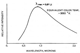
Fig. 10 Incandescent Lamps The simplest and least expensive light source used for pumping CW Nd:YAG lasers is the tungsten-filament lamp. These lamps generally have a linear filament of coiled tungsten wire inside an evacuated quartz envelope. They are manufactured in large quantities for photography and television studios, and usually are referred to as "quartz-iodide" lamps (quartz envelope with an iodine compound inside to prevent blackening of the envelope during use). The lamps have a continuous output characterized as a hot, "blackbody radiator." Figure 11 shows the spectral output of a GE type DXW 1000-watt tungsten-filament amp. As an exercise draw this output on the absorption spectra of Nd:YAG and observe the spectral match.
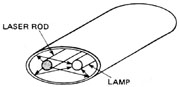
Fig. 11 Tungsten-filament lamps can be operated with either ac or dc power supplies. When using an ac supply (a simple variac), one observes that the time variations in the lamp current are significantly reduced in the light output from the filament because the large thermal mass of the wire will not allow the temperature to fluctuate rapidly. The laser output will usually have less than 10% of a 120-hertz frequency component due to the alternating line voltage oscillations. Pumping Geometries The final consideration in optical pumping is geometrically focusing the pump light into the laser rod. With a helical pumping lamp this is simple since the rod is in the center of the coiled lamp and a cylindrical reflector surrounds the lamp. This section discusses pumping geometries used with linear lamps. A reasonably efficient pumping geometry is an elliptical cylinder reflector with the lamp and rod mounted on the focii of the ellipse (shown in Figure 12). It can be shown that, in a plane perpendicular to the cylinder axis, a ray emanating from one focus of an ellipse and reflecting off the wall will cross through the other focus. Greater pumping efficiency is achieved with the rod and lamp as near one another as possible with an ellipse of low eccentricity.
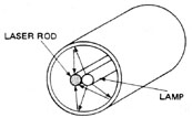
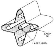
Fig. 12 A simpler, but less efficient reflector geometry is a round cylinder with the rod and lamp as close as possible to each other in the center (shown in Figure 13). Other geometrical arrangements can be used, such as the four-lobe elliptical reflector, Figure 14, and the spherical reflector, Figure 15. While all these geometries are in use, the most common are single ellipses with one lamp and double ellipses with two lamps.
Fig. 13
Fig. 14
Fig. 15 Summary Solid-state lasers consist of a solid laser rod that is optically pumped with light from a lamp. The three most popular solid-state laser materials are Nd:YAG, Nd:glass, and ruby. Of these, only the Nd:YAG can be operated in the CW mode. Ruby is usually not operated CW because it is a three-level laser and intense pumping is required to maintain a population inversion. If this pump power is applied continuously, serious cooling problems result. Nd:glass cannot be operated as a CW laser because of low thermal conductivity. The center of the rod becomes too hot for de-excitation of the lower laser level and the population inversion is destroyed. When operated in the pulsed mode, Nd:glass produces the highest energy pulses and lowest pulse repetition rate. Nd:YAG produces the lowest energy pulses with the greatest pulse repetition rate. Ruby falls between the two. The greatest consideration in the design of a solid-state laser is spectral matching of the pump source to the absorption spectrum of the laser rod. Xenon flashlamps provide the most efficient operation of ruby lasers. Krypton arc lamps and flashlamps are best with neodymium lasers. The lamps may be helical with the rod in the center of the helix for best optical coupling, or they may be linear with the same inner dimensions as the laser rod dimensions. In this case, the lamp and rod are enclosed in a pumping cavity that reflects most of the pump light into the rod.
1. Make copies of each of the lamp output spectra shown in this module and draw the Nd:YAG absorption spectrum on each with colored pen or pencil. Discuss how well each of the lamps matches the Nd:YAG absorption spectrum. 2. Explain the reason for each of the following conditions:
3. Obtain a copy of the Chemical Rubber Company Handbook of Lasers. Make a table comparing the properties of ruby, Nd:YAG, and Nd:glass. 4. Discuss the differences in the absorption spectra of Nd:YAG and Nd:glass and the reasons for the differences. 5. List the approximate range of sizes in which each type of laser rod is available, and explain the size limitations of each. 6. Compare the output energy per pulse and pulse repetition rates of the three laser types in pulsed operation. 7. Explain how the output spectrum of a flashlamp varies with the current density in the lamp. 8. Examine and measure the optical pumping cavity of a solid-state laser, and make a scale drawing showing a cross section of the cavity. Include all dimensions. 9. Explain which pump sources may be used with the following lasers. State the best pump source for each and why it is superior for that application:
Pulsed solid-state laser system Instruction manual for system Safety goggles for system Calorimeter Photodiode for pulse shape measurement Oscilloscope Footprint paper (exposed and developed photographic paper) Positive lens with 2-inch focal length Samples for irradiation (paper, wood, metal, plastic) HeNe laser CW Nd:YAG laser system Instruction manual for system Safety goggles for system Power meter Nd:YAG beam display screen UV light source to illuminate screen Beam blocks Oscilloscope camera
In this laboratory the student will operate a pulsed solid-state laser system and a CW solid-state laser system, and will observe and measure the output power and energy of each. Students should read all instructions and the lab report sections before beginning. Operation of a Pulsed Solid-State Laser 1. Read the instruction manual for the pulsed solid-state laser. 2. Identify all controls of the pulsed solid-state laser, and go through a "dry run" operations check without turning on the laser. 3. Check with your lab instructor and operate the pulsed solid-state laser according to the approved procedures. Observe all safety precautions. Safety goggles should be worn at all times during laser operation. 4. Set up a beam measurement system for the pulsed solid-state laser. The calorimeter input aperture should be located between two and three feet from the laser output aperture and should intercept the entire output beam of the laser. The photodiode should be placed to receive a small portion of the laser light without receiving flashlamp light. One method of accomplishing this is to place the photodiode to intercept laser light reflected from the calorimeter. Another is to place a microscope slide in the output beam to split a small percentage of the beam to the photodiode. A third method is to place the photodiode to intercept the beam from the laser high-reflectivity (HR) mirror. If this is done, the distance should be great enough to allow sufficient divergence of the flashlamp light to reduce its effect, or a narrow-pass filter for isolation of the laser wavelength should be used. Connect the photodiode to the oscilloscope. 5. Operate the pulsed solid-state laser. Measure the energy of the laser pulse and observe the pulse shape on the oscilloscope. 6. Attach the camera to the oscilloscope and photograph the laser pulse. Record all pertinent data. 7. Place the footprint paper in the beam path and fire the laser to obtain a beam profile. 8. Place the lens in the beam path and place irradiation samples at the focal point of the lens. A HeNe laser aligned coaxial to the pulsed laser beam will facilitate alignment and focusing. 9. Irradiate various samples with the laser and observe, describe, and record the results. 10. Upon completion of this laboratory, secure the laboratory and return the laser and associated equipment to its original condition.
Operation of a CW Solid-State Laser 1. Read the instruction manual for the CW Nd:YAG laser system. 2. Identify all controls of the laser and go through a "dry run" operations check. 3. Check with your lab instructor and operate the CW solid-state laser according to approved procedures. Observe all safety precautions. Safety goggles should be worn at all times during laser operation. 4. Place an appropriate power meter to intercept the output beam of the laser and measure the output power. 5. Connect the output of the power meter to the oscilloscope and observe the ripple in the laser output. A separate photodiode may also be used for this purpose. 6. Place the lens in the laser beam and place irradiation samples at the focal point of the beam. Irradiate various samples and observe the results. 7. Upon completion of this laboratory, secure the lab and return the laser and associated equipment to its original condition.
Laboratory Report This laboratory requires two separate reports, one for each laser system studied. Each report should include a description and sketch of the laser used as well as all other equipment. Each should also include all data taken on the laser system, along with descriptions of experimental procedures and drawings of setups. Also include descriptions of the effect of the laser on the irradiation samples.
Lengyel, Bela A. Introduction to Laser Physics. New York: John Wiley and Sons, Inc., 1966. O’Shea, Donald C.; Callen, Russell W.; Rhodes, William T. Introduction to Lasers and Their Applications. Reading, MA: Addison-Wesley Publishing Co., 1977. Ready, John R. Industrial Application of Lasers. New York: Academic Press, 1978. Weast, Robert C. Handbook of Lasers. Chapter 2. Cleveland, OH: Chemical Rubber Company Press, 1971.
|