| This version reflects the comments of the core participants as reviewed and incorporated in accordance with CORD's FIPSE-supported Curriculum Morphing Project. | |
| MODULE 3-1 POWER SOURCES FOR CW LASERS Continuous wave (CW) lasers are those that emit a continuous beam of coherent light. The excitation mechanism of such lasers must supply a continuous power to the active medium to sustain lasing at a constant rate. This is usually accomplished in CW gas lasers by a constant electrical current through the gaseous active medium. In CW solid-state lasers, the rod is excited by the optical energy from a CW pumping lamp. This lamp often has electrical characteristics similar to those of a gas laser tube and must carry a constant current for CW laser operation. This module describes the power sources used to excite a variety of CW lasers. Topics discussed include the electrical characteristics of gas discharges, gas lasgr tubes, and optical pumping lamps; the basic components of CW electrical power supplies; and the power supply designs used with several common CW laser types. Electrical requirements are also present in the charging supplies of pulsed lasers. The electrical design of the charging section of such power supplies is frequently similar to one of the CW power supplies described in this module. At the conclusion of this module, the student will build and operate a power supply for a CW HeNe laser in the laboratory.
Upon completion of this module, the student should be able to:
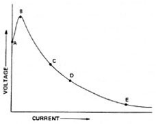
Electrical Characteristics of Gas Discharges All gas discharges operated in the glow discharge region have electrical characteristics similar to those indicated in Figure 1. The voltage and current values and the exact shape of the curve depend on the gases involved, the gas pressure, and the length and diameter of the discharge tube.
Fig. 1. Before ionization, the current through the gas is essentially zero. Increasing the voltage on the gas sample results in a small prebreakdown current due to a very small amount of easily ionized matter, which is always present in a gas near room temperature (point A). Increasing the applied voltage further will increase this current slightly until the breakdown voltage is reached (point B). At this voltage level, a significant number of atoms become ionized because of the high electric field present in the gas. The free negative electrons are attracted toward the anode, and the heavier positive ions toward the cathode. This increases conductivity of the gas and lowers the electrical resistance of the discharge. The electrons are sufficiently accelerated by the electric field to free other electrons through collisions with gas atoms or molecules. Thus, as current increases (from point C to point D in Figure 1), ionization increases and voltage across the discharge tube decreases. This means that an increase in current results in a decrease in resistance. This property of gas discharges is called negative dynamic resistance. This does not mean that the resistance of the tube is a negative value, but that the slope of the voltage-current curve has a negative value. Current through the gas will increase until it is limited by some other electrical component in the circuit, or until the power supply can no longer sustain the current. In the case of low-current CW devices such as HeNe laser tubes, the current is limited at a lower level (point C). In the flashlamps of pulsed solid-state lasers, current is allowed to increase to a value of many kiloamps (point E) before energy stored in the capacitors is exhausted. Power Supplies for Gas Discharge Devices Power supplies for all gas discharge devices—whether gas laser tubes, flashlamps for pulsed lasers, or photographic flashtubes—are designed according to the voltage-current curve of the particular system involved. For a continuous electrical discharge through the gas, three essential elements are required in the electrical power supply:
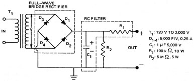
Current through the gas-filled device may be controlled or regulated, but the voltage is usually not. Once the discharge is established, the voltage across the discharge depends on the characteristics of the gas and the current. Thus, gas-filled devices are current-controlled rather than voltage-controlled. This is a handy characteristic in the case of gas lasers because the population inversion is dependent upon current and not voltage. Power Supplies for CW Gas Lasers Power supplies used in CW gas lasers are current-limited or regulated dc power supplies. The same basic power supply designs are used for the charging supplies for energy-storage capacitors in pulsed lasers as well as for many other dc power requirements. Helium-Neon Lasers Several configurations of power supply are commonly used in HeNe lasers. Similar types of supplies with different voltage and current capabilities are often used in other gas lasers. Figure 2 shows a full-wave bridge rectifier with an RC filter. When the upper end of transformer T1 is positive, current flows through diodes D1 and D4, charging capacitor C1 to the peak voltage V of transformer T. When the lower end of T1 is positive, current flows through D2 and D3, once again charging C1 to V. R1 (ballast resistor) acts as both the filter element and the current limiter. R2 is a bleeder resistor that allows the voltage to drain slowly from C1 when the supply is turned off. Component values given are those for operating a HeNe tube with a discharge length of approximately 40 cm. The resistance of R1 or the input voltage is usually varied to give the desired current.
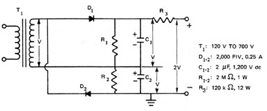
Fig. 2 While some HeNe laser manufacturers use the bridge rectifier circuit, most employ the voltage-doubler circuit shown in Figure 3. This type of power supply has the advantage of a lower-voltage transformer, lower-voltage diodes, and lighter weight.
Fig 3.
When the top of T1 is positive, current flows through D1, thereby charging C1. When the bottom of T1 is positive, current flows through D2, charging C2. Since the capacitors are in series, the two voltages add to give the output voltage. R1 and R2 are bleeder resistors. Ballast resistor R3 acts as a filter element and is also the current limiter. Component values given are for the operation of a HeNe laser tube with a discharge length of approximately 35 cm. Once again, R3 or the input voltage is usually varied to give the desired current through the tube. Figure 4 shows an alternate type of voltage-doubler circuit sometimes used in HeNe laser power supplies. When the bottom of T1 is positive, current flows through D1, charging C1 to V. When the top of T1 becomes positive, its voltage and that of C1 are added in series. The current flows through D2, charging C2 to 2 V. Other components have the same functions described above.
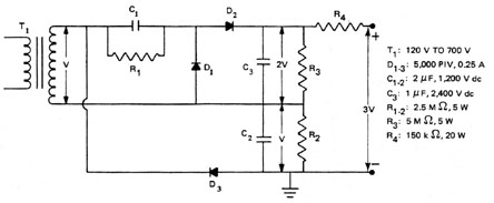
Fig. 4. Laser manufacturers often find it more economical to use the same standard power supply parts for several lasers. The same transformer used with a voltage doubler for a short HeNe laser tube can be used with the voltage tripler shown in Figure 5 for a longer tube requiring a higher operating voltage. A careful examination of this circuit will reveal that it is a combination of the two circuits shown in Figures 3 and 4. Capacitor C3 is charged to a voltage of twice the peak output voltage of the transformer.
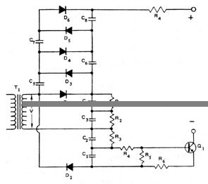
Fig. 5 In each of the circuits described thus far, the current control has consisted of a ballast resistor that limits the current of the laser tube to a specific value for a given value of input voltage. Operating such power supplies at different line voltages results in different tube currents and operating characteristics. To overcome this situation, a current-regulated HeNe laser power supply is frequently used (as shown in Figure 6). The current regulator consists of a transistor in series with the cathode of the laser tube. This circuit maintains a constant tube current although driven by a varying line voltage.
Fig. 6 Figure 6 also shows the automatic starter or ignitor circuit most commonly used in HeNe lasers. In this circuit, the first and second half cycles charge capacitors C1 to C4 to a total voltage of 2 V. The second half cycle also charges C5 to 2 V. The third half cycle charges C6 from C5 with the result that the voltages across C5 and C6 are now each V (assuming C5 = C6). This process continues on each successive cycle with C5 being charged to 2 V and then transferring part of its charge to C6 until both capacitors are charged to 2 V or the laser tube fires. A similar process transfers charge from C6 to C7 and then on to C8. The total starting voltage possible for the circuit in Figure 6 is 10 V. When the tube fires, its resistance drops sharply. The voltage across capacitors C1 to C4 is sufficient to maintain the discharge. Diodes D3 through D6 conduct this current, bypassing capacitors C5 through C8. The capacitors in the start circuit have relatively low capacitance (0.001 – 0.005 m F) since they must deliver only a single low-current but high-voltage pulse to ignite the lamp discharge. This type of starter circuit may be used with any of the operating supplies described previously. In each case, it would be connected across the diode that is directly connected to the ballast resistor. The number of capacitor-diode pairs in the starter stack varies from two to five, depending on system characteristics. Larger HeNe lasers may use a push-button start circuit, which will be described later in this module when we discuss ion lasers. HeNe laser tubes usually operate in the 4-6 mA range, but some use currents as high as 10 mA. This is rare in more modern designs, as higher currents tent to shorten tube life. The sustained voltage for a 30-cm discharge at 5 mA is around 1000 V, while 5000 V is typically required to start the discharge. Metal Vapor Lasers Helium-cadmium (HeCd) and helium-selenium (HeSe) gas-discharge lasers operate in the same general range on the voltage-current curve as HeNe lasers. Such lasers employ a metal vapor in the singly ionized state and helium as a buffer gas to sustain lasing. The current required for metal vapor ion lasers, however, is typically 25-100 mA, while voltages range from 2000 V to 5000 V, depending on the laser tube. Power supplies for such lasers are very similar to the HeNe supplies with higher current-handling capabilities. It is often desirable to operate metal vapor lasers with a grounded anode. (Note that HeNe lasers usually have grounded cathodes.) The most common method of achieving this is to use the circuit shown in Figure 4 with the diodes reversed. Because the resistors in the RC filter would dissipate large powers at the required current, the RC filter is usually replaced with an LC filter. Figure 7 shows such a power supply. The current limiter of this supply consists of a transistorized current regulator similar to that shown in Figure 6.
Fig. 7
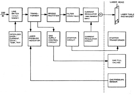
The ignitor circuit for a metal vapor laser may be either an automatic starter, like those used in most HeNe lasers, or a push-button starter. Metal vapor lasers require close control of the tube temperature for the correct vapor pressure of metal atoms. Thus, metal vapor laser power supplies must include heaters as well as temperature sensor and control circuitry. Carbon Dioxide Lasers CO2 laser tubes typically operate at currents of 30 to 50 mA and voltages of about 10,000 V per meter of tube length. The basics of the power supply design are similar to those for HeNe lasers. Larger CO2 lasers usually havg two or more laser tubes electrically operated in parallel. In such systems, a single operating supply powers all tubes, but each has its own separate current regulator to account for variations in the individual discharges. Three-phase power is frequently used with larger CO2 lasers since it provides greater efficiencies in high-power electrical systems. Ion Gas Lasers Argon and krypton lasers have very different power requirements from the lasgr types considered thus far. HeNe, metal vapor, and CO2 lasers all require relatively low currents and high voltages. Conversely, noble gas ion lasers operate at higher currents and lower voltages. The higher current densities are necessary to maintain a high rate of electron collisions to maintain an appropriate ionization level of gas atoms and excitation of the ions. Ion lasers typically operate at tube currents of 5 to 60 amps with voltages from 200 V to 600 V, depending on tube size and output power. Several amps are also required to operate a solenoid that produces a strong magnetic field within the tube. This magnetic field helps to increase the current density in the center of the bore. Figure 8 is a block diagram of a typical ion laser power supply. For larger ion lasers, three-phase power is used. The line switch is a circuit breaker that may be tripped by a voltage signal from several safety and circuit protection devices. The function of these devices will be covered in detail in the section on safety devices. The transformer is usually an auto-transformer with several input taps. Changing taps on one model allows the user to obtain a transformer output of 220 V for input voltages between 200 V and 240 V. The rectifier is a full-wave bridge type. The filter is a choke input filter of the same configuration as shown in the dotted square in Figure 7.
Fig. 8
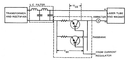
Current is regulated and controlled by a pass transistor bank. A partial schematic of such a bank is shown in Figure 9. The collectors of the transistors are connected in parallel and connected through an ammeter to the laser tube. The bases of the transistors are connected in parallel and receive a control voltage from a current regulator circuit. A small ballast resistance (3 to 5 ohms) is connected in series with each emitter to help equalize current through the transistors. Controlling the voltage applied to the bases of the transistors controls the voltage drop across the pass bank and, thus, the current through the laser tube. Figure 9 show only a small segment of a transistor pass bank. Practical banks consist of as few as 10 transistors in parallel to as many as a hundred in series and parallel combinations, depending on the voltages and currents involved.
Fig. 9
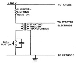
The voltage regulator circuit maintains a constant current level and contains a control input that may be used to set the operating current. In some models, the same current regulator supplies both the laser tube and an electromagnet. In larger models, the magnet usually has a separate current control. In many systems, a beam splitter is used to sample the output beam and provide an input to the current regulator circuit that will vary tube current to maintain a constant output power as tube or power line conditions change. Although ion lasers operate at a few hundred volts, several thousand volts are required to initiate the discharge. Figure 10 is a simplified diagram of a typical ion laser starter circuit. When the push-button starter switch is closed, a current flows through the primary of the trigger pulse transformer. This current is limited by a current-limiting resistor. When the starter button is released, the current in the transformer primary is broken abruptly. The collapsing magnetic field excites a high-voltage pulse in the transformer secondary that is connected to a starter electrode in the laser tube. This is the same mechanism used to produce the ignition spark in an automobile electrical system. More sophisticated controls are often included, but the process is essentially the same. This type of push-button starter is often found on other types of lasers as well.
Fig. 10
Ion lasers typically operate at tube pressures of only a few hundred millitorr and require a gas refill after several hours of operation. Provisions are usually made to add 10 millitorr of gas at a time from a gas reservoir included in the laser tube. A thermocouple gage is included for measuring the gas pressure, and a pair of solenoid-controlled valves allows the addition of the desired amount of gas to the laser tube. Power Supplies for Optically Pumped
Fig. 11
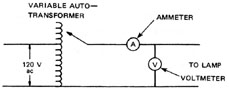
Since these lamps are not gas-discharge devices, they do not exhibit negative dynamic resistance and do not require the complicated power supplies typical of gas-filled devices. Their greatest advantage is that they may be operated by simply connecting their terminals to the proper voltage. Quartz-halogen lamps are designed to operate on ac power at either 120, 208, or 240 V. In most cases, the power supply for a laser using this type lamp consists of a power switch with appropriate interlocks and nothing else. Figure 12 shows a simple circuit for controlling the laser output with an input variable autotransformer and monitoring meters for lamp current and voltage.
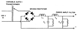
Fig. 12 Ac operation of quartz-halogen lamps results in a slight ripple in the laser output at twice the frequency of the ac line voltage. This can be eliminated by using a dc current for the lamp from a power supply similar to that shown in Figure 13. This is the same basic design as the operating supply of an ion laser, but it includes no current regulator. Current regulators may be used if desired.
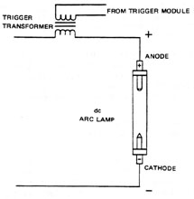
Fig. 13 Krypton Arc Lamps Figure 14 shows a typical krypton arc lamp used to pump Nd:YAG lasers. This type of lamp is more efficient than the quartz-halogen pumping lamp and is capable of higher powers. Krypton arc lamps are used in most larger Nd:YAG lasers.
Fig. 14
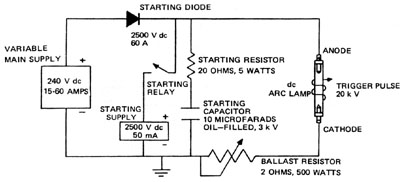
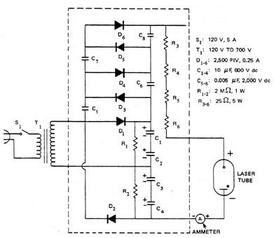
Fig. 15 Basically, the power supply works as follows: The main supply is turned on and set at the proper voltage level to deliver the necessary power. At the same time, the starting supply is also turned on. Closing the starting relay charges the starting capacitor to about 2500 V. The starting diode is now back-biased, preventing discharge of the capacitor through the main supply. The ballast resistor is set to its maximum value. When the trigger pulse is applied, the gas in the flashtube is ionized and begins to conducts. The starting capacitor now discharges through the starting resistor and provides a current pulse that releases several amps. When the voltage on the capacitor reaches the voltage level of the main supply, the starting diode becomes forward-biased and begins to conduct. If the main supply is unregulated, a ballast resistor prevents a high-current surge that might damage the lamp. When the lamp is in continuous operation, the ballast resistor may be removed from the circuit to eliminate unnecessary power dissipation. If the main supply is current-regulated, a ballast resistor is unnecessary. To better understand the triggering sequence, refer to Figure 1. The initial trigger pulse carries the lamp over the voltage peak at point B but does not lower resistance to the point where the main supply will sustain a discharge. The current surge from the starting capacitor is sufficient to lower the flashlamp resistance to point E on the curve. At this point, the main supply takes over and the lamp operates continuously. The trigger pulse may be supplied by a system similar to the one used for the ion laser, but a triggering module is more common. This module produces a higher-voltage spike and is, therefore, more dependable. Figure 16 shows such a trigger module. Capacitor C1 is charged to 1000 V through R1. Capacitor C2 is initially uncharged due to R2.
Fig. 16 When the push-button switch is closed, C2 charges through the primary of T2. This applies a voltage pulse of 300-500 V to the grid of the tube. The tube, called a krytron, is filled with krypton gas. (This type of circuit is frequently called a "crowbar switch" because it has the same effect as dropping a crowbar across the terminals of capacitor C1 and transformer T1.) The grid-to-cathode voltage is sufficient to ionize the gas. This allows current to flow from the anode to the cathode. Then C1 discharges very rapidly through the primary T1, producing a pulse of abowt 20 kV in the secondary. The fourth electrode is called a "keep alive." It maintains an ionization level in the krytron to make triggering easier. Figure 17 shows another common configuration for triggering the arc lamp, called series injection triggering. In this case, the trigger pulse is applied directly to the lamp anode. This requires a special series trigger transformer to handle the high currents of the discharger and the high voltages produced during triggering. In this case, the secondary of the trigger transformer plays a dual role in acting as a choke inductance in the power supply circuit.
Fig. 17 The two triggering methods discussed here are also frequently used to trigger the flashlamps in pulsed solid-state lasers. Power Supply Safety Features All laser power supplies incorporate several safety features. Some of these are for the safety of the operator; others protect the equipment itself. Some of the more common safety features are discussed here.
Summary Most CW lasers consist of gas-discharge devices that are powered by a continuous current flow. In these devices, a high-voltage pulse is needed to initiate the discharge. An increase in the current results in a decrease in the voltage across the gas-filled device. Thus, the power supply for such a device must include three basic functional components. The starter or ignitor circuit provides an initial pulse for ionization of the gas. The operating supply provides the necessary current and voltage for continuous operation. The current limiter establishes the maximum current that the power supply can deliver. In high-voltage, low-current power supplies, filtering is often accomplished with RC filters, and the current limiter is often a ballast resistor. At higher currents, LC filters are used, and current regulators replace the ballast resistors for current control.
Power cord Transformer, 120 V to 700 V, 30 mA SPST switch, 120 V, 5 A 6 diodes, 2000 PIV, 25 A 4 capacitors, 10 m F, 600 V dc 4 capacitors, 0.005 m F, 2000 V dc 2 resistors, 2 MW , 1 W 6 resistors, 25 kW , 5 W HeNe laser tube with discharge length less than 30 cm Clip leads Perforated phenolic board, 12" × 12" Solderless spring terminals dc milliammeter, 0-20 mA VOM Capacitor shorting bar
1. Use VOM to check all diodes. They should show a relatively low forward resistance and a very high reverse resistance. Check all resistors for proper values. Check capacitors for short circuits. The resistance of the 10-m F capacitor will be low initially but will increase to infinity within seconds. If this does not happen, it is shorted or leaking. The resistance of the 0.005-m F capacitors will rise to infinity immediately. Replace any defective components. Be careful to discharge the charged capacitors after this check. 2. Lay out all power supply components except transformers, switch, and power cord on the perforated board. Arrange them so they can be easily connected as shown in Figure 18.
Fig. 18
Malmstadt, H.V.; Enke, C.G.; and Toren, E.C., Jr. Electronics for Scientists. New York: Dover Publications, Inc., 1969. O’Shea, Donald D.; Callen, Russell W.; and Rhodes, William T. Introduction to Lasers and Their Applications. Reading, MA: Addison-Wesley Publishing Co., 1977. Ready, John F. Industrial Applications of Lasers. New York: Academic Press, 1978.
|