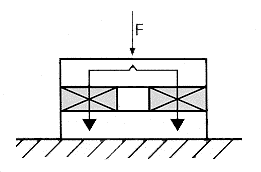
Figure 1 - Direct Force Measurement
FORCE MEASUREMENTS
Force, like any other physical phenomena, cannot be
measured without disturbing the phenomenon being measured. Most
force transducers have an elastic sensing element, whose
deformation is a measure of the acting force.
In many force measurement systems (i.e. strain gages, inductive and capacitive systems), this deformation itself must be measured. The sensing element must have enough compliance to provide sufficiently large deformation and hence useful sensitivity. These large deformations are undesirable because they limit the frequency response of the measuring system and also introduce geometric changes into the force measuring path which inevitably leads to measurement errors (i.e. linearity and hysteresis).
In piezoelectric force transducers the sensing element is the same as the transduction element which produces the electrical output signal from an acting force. Therefore, it is not necessary to measure the deformation (which will be much smaller than with other measuring systems). The resultant high rigidity of piezoelectric force transducers greatly reduces the disturbance (or geometric changes) caused by the measurement and provides an inherently high natural frequency and associated rise time. This permits the measurement of extremely fast events (such as shock waves in solids, impact printer and punch press forces) that otherwise might not be possible.
While piezoelectric force transducers are ideally suited for measuring dynamic events, they cannot perform truly static measurements. Although the electrical charge delivered under a static load can be registered, it cannot be stored for an indefinite period of time. For static measurements, highly insulated materials must be used for the transducer cables and connectors to insure a maximum discharge time constant and optimal operation of the charge amplifier (i.e. minimal drift ). Quartz is used in all Kistler force transducer designs. Since it has an ultra high insulation resistance (>1013 ohms), static measurements are more feasible with quartz than with any other piezoelectric material. In fact, quartz-based piezoelectric systems can routinely measure large forces for minutes and perhaps even hours. Low level forces can be measured "statically" for much shorter intervals. This is why Kistler piezoelectric force transducers are often described as being "quasistatic."
PIEZOTRON® force transducers use the same quartz sensing element as standard (charge output) piezoelectric units and also have a miniature, built-in charge-to-voltage converter for low impedance voltage output. This allows the usage of general purpose cable in environments where moisture or contamination would be detrimental to the high insulation resistance required with high impedance transducers. PIEZOTRON force transducers have time constants long enough for calibration, but usually not long enough for static measurements. For this reason they are usually restricted to dynamic applications..
DIRECT
FORCE MEASUREMENT
The transducer is mounted in line with the force
path and the entire force is measured (see Fig. 1). High accuracy
is obtainable and virtually independent of the point of the force
application. Transducer size and measuring range depend upon the
magnitude of the force to be measured. Load washers, force links,
load cells and force probes are all examples of Kistler direct
force transducers.
These transducers utilize a design where quartz discs (or plates) are sandwiched between two finely machined and parallel housing plates. The major differences in the individual designs are the element housing technique and the force coupling threads. A special version of Kistler direct force transducers is the patented multi-component force transducer.

Figure 1 - Direct
Force Measurement
MULTI-COMPONENT FORCE
MEASUREMENT
A multi-component force transducer consists of a
stack of quartz discs or plates and electrodes installed into a
steel housing. Each quartz disc or plate has been cut in a
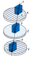
definite crystal axis, and the orientation of the sensitive axes
coincides with the axes of the force components to be measured
(see Fig. 2b). Shear (or transverse) forces must be transferred
to the transducer surface via friction. Preloading the load
washer establishes this frictional contact and allows the load
washer to measure specified shear loads. Figure 2a shows the
operating principle of a three-component force transducer. Force
F acts upon the transducer and is transmitted to each of the
discs with the same magnitude and direction. Each disc produces a
charge proportional to the force component acting on that
sensitive axis. Contrary to other measuring systems, it is not
necessary to construct mechanical devices for separating the
components.
In some applications, depending on measuring range and force footprint, it may be possible to use only one multi-component element to solve a particular problem. When larger sizes and/or ranges are necessary, a dynamometer or force platform can be constructed with more than one multi-component element. Many such prefabricated systems are available from Kistler.
 |
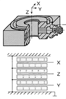 |
| Figure 2a | Figure 2b |
| Three Component Force Transducer | |
Another option is to build the multi-component elements into a customized design. In the simplest case, a multi-component dynamometer or platform consists of 4 three-component transducers placed in a rectangular arrangement between a base plate and a cover and preloaded to a specified range (see Fig. 2c). Since the outputs are in the form of an electrical charge, they can be tied together inside the platform or dynamometer housing before being routed to the connector(s) and ultimately on to the charge amplifier(s). For x, y, and z only measurements, the individual transducer outputs are tied together for a three-channel system. Other possibilities include up to eight outputs for calculating moments and point of force application.
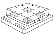
Figure 2c -
Multicomponent Dynamometer
INDIRECT FORCE
MEASUREMENT
When a force transducer cannot be installed directly
into the force path, an indirect (or shunt) force transducer can
be used. Only a portion of the total applied force will be
measured by the transducer (see Fig. 3). Although transducer size
and range are dependent upon the magnitude of the force to be
measured, they are usually less restricted than direct force
transducers. Since the measured output is only a fraction of the
total force, on site, comparison calibration is often required.
In addition, transducer sensitivity, linearity and hysteresis can
be influenced by mounting and installation conditions. If
repeatable, relative force readings are required (as is often the
case in industrial monitoring), indirect force transducers offer
an easy-to-install, cost-effective alternative.
Piezoelectric measuring pins and strain transducers are examples of Kistler indirect force transducers. These transducers offer the same advantages as any other Kistler piezoelectric unit but the quartz is packaged differently to respond to strain rather than to direct force.
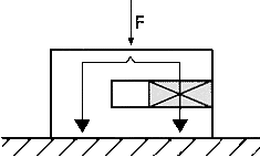
Figure 3 - Indirect
Force Measurement
| Kistler Instrument Corporation, USA, E-mail kicsales@kistler.com, http:// www.kistler.com Telephone 1-888-KISTLER (1-888-547-8537), Fax:1-716-691-5226 |