Like modern magnetometers, resistivity meters do not rely on an operator to read or
interpolate a dial reading.
Rather, the current strength is fixed and the voltage difference between the two potential
electrodes is measured and displayed. In addition, on many modern instruments it is possible
to input the electrode configuration and have the instrument directly display and store
apparent resistivity.

The portable resistivity meters used for most near-surface investigations can deliver and measure currents in the range of a few milliamperes to a few hundred milliamperes. The voltage difference between the potential electrodes can be read to within a few tens of millivolts. What these parameters mean for the absolute accuracy of the measurement when converted to apparent resistivity depends on the resistivity underlying the survey and the spacing of the electrodes. The most significant limitation to these portable systems is that the small amount of current that can be delivered into the ground limits the distance at which electrodes can be placed. At large electrode spacings, the voltage difference between the two potential electrodes can become smaller than the electrical noise associated with the electrodes and to a lesser extent the resolution of the voltmeter incorporated in the instrument. In this discussion, note that large is relative to the resistivity of the underlying material. In high resistivity environments, it will be more difficult to acquire stable resistivity estimates at smaller current electrode spacings than in lower resistivity environments.
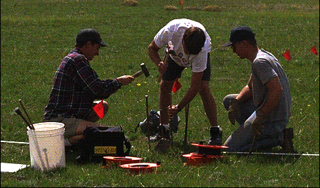
To gain a better understanding of the noise inherent to DC electrical soundings, four survey crews collected DC data over the same electrode configuration. The results of the four surveys are shown below. Notice that at the shorter electrode spacings, the apparent resistivities determined by each group are almost equal. As electrode spacings increase, the apparent resistivities, as determined by each group, become increasingly different.
AB/2 (m) | Number of Readings | ra (ohm-m)(Group 1) | ra (ohm-m)(Group 2) | ra (ohm-m)(Group 3) | ra (ohm-m)(Group 4)0.25
| 1
| 350.18
| 350.12
| 350.13
| 350.19
| 0.5
| 1
| 349.99
| 349.98
| 349.63
| 349.52
| 0.75
| 1
| 349.08
| 349.46
| 349.75
| 350.04
| 1.0
| 1
| 349.49
| 350.22
| 349.13
| 350.00
| 1.25
| 1
| 348.03
| 349.71
| 349.16
| 348.32
| 1.75
| 1
| 347.02
| 347.10
| 347.75
| 348.85
| 2.0
| 1
| 345.56
| 345.38
| 343.40
| 345.79
| 2.25
| 1
| 343.71
| 343.92
| 342.70
| 342.49
| 2.5
| 1
| 343.61
| 337.98
| 341.59
| 338.74
| 5.0
| 1
| 301.23
| 295.02
| 296.94
| 296.04
| 7.5
| 1
| 236.33
| 238.67
| 244.05
| 239.90
| 10.0
| 1
| 202.46
| 208.05
| 208.71
| 191.27
| 12.5
| 1
| 188.32
| 174.77
| 167.77
| 177.83
| 15.0
| 1
| 173.49
| 148.82
| 154.22
| 162.53
| 17.5
| 1
| 147.17
| 158.11
| 146.56
| 163.20
| 20.0
| 1
| 144.70
| 164.38
| 176.71
| 168.20
| 22.5
| 1
| 166.55
| 155.96
| 160.93
| 168.92
| 25.0
| 1
| 189.31
| 185.72
| 159.45
| 179.18
| |
To complete this portion of the exercise perform the following tasks.
