Circuit
Description
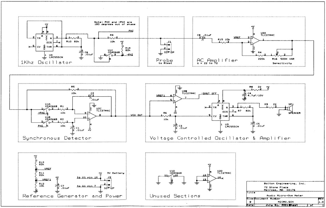
The Audio
Micro Ohm Meter uses synchronous detection to measure low value
resistances. The circuit provides a variable frequency audio tone to
indicate the resistance under test. Such a tone is invaluable when
troubleshooting shorted tracks on multi-layer circuit boards.
Timer U4
generates a 9V 1KHz square wave carrier signal that is injected into
Rtest at J1. AC amplifier U2A amplifies the signal. The sensitivity of
the circuit may be adjusted by potentiometer R16, which changes the AC
amplifier gain over a three to one range. The amplitude of the 1KHz
waveform at the output of U2A is proportional to the resistance of the
resistance under test, Rtest.
A synchronous
detector formed by U1A, U1B, and U2C demodulates the carrier signal. U1A
and U1B are driven by out-of-phase signals PHI and –PHI. Signals that
are at the same frequency as the PHI and –PHI drive signals are
integrated, and others (such as 50Hz or 60Hz) are rejected.
Timer U3
functions as a voltage-controlled oscillator that converts the
demodulated signal into a variable tone output. U2B turns off the tone
when the resistance exceeds several ohms to conserve power.
A voltage
output proportional to Rtest may be taken from the output of U2C. Note
that any track resistance between the Rtest GND node and the U1 GND node
will be included as part of the measurement. If a calibrated output is
desired, U2C may be replaced by an instrumentation amplifier to
eliminate this common-mode resistance error and +V to U4 should be
regulated to make the carrier signal a constant amplitude independent of
power supply variations.
Note that the
power and ground connections for U1, CD4066 are not shown on the part
symbol, but are shown at the bottom of the schematic, near J2. U1 pin 14
connects to +V, and U1 pin 7 connects to ground.
The circuit is
constructed out of commonly available components. Just about any op
amps, timers, or speaker will work. The specific parts were chosen to
minimize power consumption without adding a lot of cost. When
constructing the circuit, the ground track from Rtest to the carrier
oscillator should be run directly to pin 1 of U4 using heavy wire to
minimize the series resistance. Also, the ground wire from speaker SP1
should be run separately to the battery to prevent electrical noise from
the speaker from entering into the demodulation circuit. The four U2 op
amp sections may be interchanged in any way so as to simplify layout, as
may the four U1 analog gate sections.
The circuit
runs off of a single 9V battery and draws about 4mA when the tone is OFF
and 10 to 20mA when the tone is ON, depending on the type of speaker
used. The total parts cost is under $5.
Parts List
|
Reference
|
Part
|
Qty
|
Substitution
Notes
|
|
C1,C2,C3,C5,C6,C7,C8
|
0.01uF
capacitor, ceramic disk
|
7
|
0.01uF, mylar
|
|
C4
|
4.7uF/10V
Tantalum or Electrolytic capacitor
|
1
|
2.2uF to 22uF
at 10V or higher
|
|
J1
|
2 pin
connector, to Rtest
|
1
|
|
|
J2
|
2 pin
connector, to 9V Battery
|
1
|
|
|
R1,R2,R3,R5,R6,R12,R15
|
10k, 5%, 1/4W
|
7
|
10k to 15k,
1/4W
|
|
R4
|
220k, 5%, 1/4W
|
1
|
180k to 220k,
1/4W
|
|
R7,R10,R11,R13,R14
|
82k, 5%, 1/4W
|
5
|
82k to 100k,
1/4W
|
|
R8,R9
|
22 ohm, 1/4W
|
2
|
22 ohm to 33
ohm
|
|
R16
|
500K VAR POT,
sensitivity adjust
|
1
|
500k to 1meg
POT
|
|
SP1
|
SPEAKER, 8 ohms
or higher
|
1
|
|
|
U1
|
CD4066B CMOS
Analog Gate
|
1
|
|
|
U2
|
TLC27M4CN Quad
Low Pwr Op Amp
|
|
LM324
|
|
U3,U4
|
LMC555CN Low
Power Timer
|
2
|
LM555
|
|