

With partial support of NSF-CCD 95-55230
Electromagnetic (Terrain Conductivity) Method
Warning: These online notes are meant primarily to provide practical information. The Web pages cannot replace your notes from the physics-based class lectures.
Theory
The simplest electromagnetic (EM) methods rely
on the fact that an imposed, alternating primary magnetic field Hp
will give rise to a secondary magnetic field Hs
whose strength is directly proportional to the electrical
conductivity ![]() of a material:
of a material:
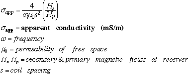
Electrical conductivity is the inverse of the
better-known quantity resistivity ![]() and refers to how easily current moves through a material. For a constant
value of the input (primary) magnetic field, the magnitude of the induced
secondary magnetic field will be much larger for a high conductivity material
than for a low conductivity material.
and refers to how easily current moves through a material. For a constant
value of the input (primary) magnetic field, the magnitude of the induced
secondary magnetic field will be much larger for a high conductivity material
than for a low conductivity material.
The electrical conductivity of various soil and rock types depends on many factors. Some of these factors are the degree of saturation; the degree of compaction; the salinity of pore waters; and soil composition. Like most geophysical methods, electromagnetic techniques cannot uniquely determine the composition of the subsurface. The instruments instead measure a physical parameter from which the composition and structure can be deduced.
The EM31 and EM34 measure electrical conductivity in units of milliSiemens per meter (mS/m). the EM31 is a single operator instrument that has a fixed spacing of 3.7 m between the coils. Two operators are required for the EM34, which has coils that can be spaced at 10 m, 20 m, or 40 m.
EM-31 Terrain Conductivity Meter
 |
The EM-31 consists of a transmitter coil and a receiver coil
with a control unit in the middle. The instrument is normally carried above
the ground at hip-level, but it can also be operated directly on the ground.
In normal operation, no part of the instrument ever needs to come in contact
with the ground. Usually the instrument is carried alongside the operator,
so that it is oriented parallel to the operator's steps.
The transmitter coil transmits the primary magnetic field. The receiver coil measures the induced secondary magnetic field and displays the constant of proportionality between the two magnetic fields (the electrical conductivity) on the control unit. The EM31 nominally senses to a depth of about 5-6 m. Click on the picture to see a bigger version of the image. |
 |
This demonstrates how the EM-31 is assembled. The long white pieces
are usually stored in the cradles beneath the blue control unit. During
assembly, these long white pieces (which contain the coils) are detached
from the cradles and the connections between the control unit and the transmitter
and receiver are completed. We have a protocol sheet available to
guide you in assembly and calibration of the instrument.
Click on the picture to see a bigger version of this image. |
EM-31 Control Unit Configuration
 |
Once the control unit (shown upside down in the previous image) is
flipped over, then the top pops off and instrument set-up and calibration
begins. This image shows the dials and digital readouts on the face of
the control unit.
The scale dial tells the instrument whether the expected terrain conductivity lies in the range of 0-200 mS/m (set dial on 100) or > 200 mS/m (set dial on 1000). If the scale dial is not set correctly, the DL720 data logger (not shown here) will still log the measured value correctly. The mode dial is primarily used during instrument calibration and setup. During normal operation, the dial is set to "oper". The coarse-fine dials are used for adjustment during calibration and setup. Terrain conductivity values are displayed in the data readout window. The orange reading button is located on the instrument's transmitter. When the operator reaches the spot at which s/he wishes to take a reading, the button is pressed and the data are collected. When used with a data logger (not shown), it is also possible to run the EM31 in continuous mode. In this case, it is not necessary to press the reading button at each survey point. Click on the picture to blow up the image. |
EM-31 Field Operations and Data Logging
In the field, we follow the set-up procedure described on the protocol sheet that we carry with the unit. Relevant information about each survey and line is recorded on the GT EAS EM31 data log sheet.
This picture of the EM-31 in operation along a survey line at the Georgia Tech Research Facility (GTRF) geophysics test bed facility in Cobb County, Georgia demonstrates typical usage. Note that the EM31 can be operated either with or without a datalogger. When no logger is available, data are recorded by hand directly off the digital readout screen.
The image shown here demonstrates operation of the EM-31 in vertical mode. In this mode, the digital readout faces upward during the measurement. The designation of vertical refers to the fact that the coils inside the long white tubes (transmitter and receiver) are oriented parallel to the ground during the measurement, resulting in a vertical EM field. The EM-31 can also be operated in horizontal mode, which involves rotating the entire instrument 90 degrees about an axis aligned with the transmitter-receiver tubes. In this configuration, the digital readout faces toward or away from the operator. In horizontal mode, the coils in the transmitter-receiver tubes are aligned perpendicular to the ground during the measurement and the resulting EM field is parallel to the ground.
EM31 data are also often collected in different directions at the same survey location. For example, at a single spot, the operator might take one reading in the vertical mode facing east along a survey line and then turn 90 degrees and take another reading in the vertical mode facing south, with the instrument perpendicular to the survey line. Such surveys are particularly good for detecting whether there is a directional component to the subsurface feature. Over a pipe oriented parallel to the survey line, one would expect different terrain conductivity values when the measurement is taken parallel to the survey line instead of perpendicular to the survey line.
Finally, the EM31 records both the inphase (measured in parts per thousand or ppt) and quadrature (measured in mS/m) phase parts of the response signal. These components respectively correspond to the real and imaginary components of the projection of the secondary field on the primary field. For now it is enough to know that the quadrature component is the one most often used for general surveying for many environmental applications and that the inphase component is most useful for locating metallic objects.
This is sample quad phase data from the EM31. The high values on the left side of the diagram were obtained close to the Atlantic Ocean and reflect the presence of saltwater (very high conductivity; about 5000-6000 mS/m) in the near-surface. The values drop off quickly toward the interior of the island. The feature at ~1150 ft coincides with a recently dug shallow irrigation well that pulls water out of the surficial aquifer. The local increase in conductivity near this well indicates that a cone of saltwater may be developing below the pumping site. Using simple formula and adopting assumptions about the conductivities of the freshwater-saturated and underlying saltwater-saturated sand layers, it is possible to invert the EM31 data for the depth to the freshwater-saltwater interface beneath this barrier island. (See Problem 2 of Problem Set 2.)
Since the EM-31 can only sense to 5-6 m below the surface, the low background values obtained in the interior of this island likely indicate that the freshwater-saltwater interface lies at depths greater than this nominal sensing depth. The EM-34, an instrument related to the EM-31 but more cumbersome to use, can sense to depths as great as ~60 m when used in vertical mode with maximum coil spacing (40 m).
EM-34 Terrain Conductivity Meter
The primary difference between the EM-31 and the EM-34 terrain conductivity instruments is the depth to which they can detect conductivity variations. Since the transmitter and receiver coils are carried separately for the EM-34, the spacing s between the coils can be varied.
 This
picture shows the operation of the EM-34 in horizontal mode. The coils
are vertical, while the induced EM fields are horizontal, perpendicular
to the plane of the coils. For this generation of the EM-34, the coil separation
can be 10 m, 20 m, or 40 m. In horizontal mode, the nominal depth of penetration
is ~75% of the coil spacing. In vertical mode, penetration depth is 150%
of the coil separation distance. Click on the image
to see a larger version.
This
picture shows the operation of the EM-34 in horizontal mode. The coils
are vertical, while the induced EM fields are horizontal, perpendicular
to the plane of the coils. For this generation of the EM-34, the coil separation
can be 10 m, 20 m, or 40 m. In horizontal mode, the nominal depth of penetration
is ~75% of the coil spacing. In vertical mode, penetration depth is 150%
of the coil separation distance. Click on the image
to see a larger version.
Basic Interpretation
The response function Rv for the EM-31 or EM-34 operated in vertical mode is given by:
![]() Note that z in this equation
does NOT refer to depth, but rather to a dimensionless
ratio of depth L to intercoil spacing s.
Note that z in this equation
does NOT refer to depth, but rather to a dimensionless
ratio of depth L to intercoil spacing s.
For a two-layer model (one layer over a half-space):
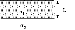
the apparent conductivity is given by:
![]() where Rv
(z) is the response function evaluated at z=(thickness
L of layer 1/ intercoil spacing). The thickness of layer 1 can then
be found by solving for L.
where Rv
(z) is the response function evaluated at z=(thickness
L of layer 1/ intercoil spacing). The thickness of layer 1 can then
be found by solving for L.
Return to EAS 4420 Home