Ground Testing on Bonded Ground Systems
A fairly common headache faced by electrical contractors results
from a miscommunication that can foul up a grounding installation.
Upon completion of a job, it is generally required that the local
ground bed be tested to assure that it meets a design spec. This
is frequently written into the contract. But the contract will
also require that the grid be tested before connection to the
electrical system. Oops! Eager to finish the job and move on,
someone has already hooked up the conductor from the ground buss.
Since this may be a welded connection, the contractor may face
the annoying task of sawing it off and re-welding.
Is this necessary? Not necessarily! It may be wise to consult
the client first, but a connected ground can still be tested,
employing an adaptation of the Fall of Potential method and a
Megger DCM300E Clamp-on Leakage Tester. Here's how:
The problem is that, when connected to the electrical system,
the local ground is in parallel with the utility ground. It can
be tested, yes, but the result is the total resistance of the
combined grounds, and tells relatively little about the contribution
of the grid on site. This occurs because the test current divides,
and goes to ground any and all ways it can. If we knew the current
in the separate grounds, we could calculate their individual resistances.
We can!
Because the DCM300E can measure down to micro amps,
it can accurately sense the small currents comprising a ground
test (this is what separates it from a generic clamp-on). Set
up the ground test in typical fashion, energize the tester and
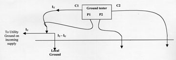
get a reading. Now, clamp the DCM300E in two places: around the
current lead to the ground under test, and at some convenient
point above the local ground, leading back to the utility (say,
the ground conductor down from the service entrance). You now
know the total current, and that portion flowing through the utility
ground. Next, take the resistance reading from the ground tester.
By Ohm's Law, calculate the voltage drop caused by the soil. The
difference between the two current measurements will represent
that portion going to the local ground. Use it and the voltage
drop to calculate, via Ohm's Law, the desired resistance (a diagram
and sample calculation follows).
There will be some loss of percentage accuracy, but you would
hope that your grounding job isn't shaving the system spec that
close, anyway. And it sure beats hacking and welding!
Sample Calculation; Testing A System-Connected Ground
Ground Tester in typical Fall of Potential test configuration;
Reading: 1.9 W (RT)
DCM300E clamped over lead from C1;
Reading: 9.00 mA (IT)
Repeat, clamped over ground conductor from service entrance;
Reading: 5.00 mA (IU)
Voltage drop from selected volume of soil to point of P2 probe
(from resistance of soil around local ground):
V = ITRT = 0.009 x 1.9 = 0.017 V
Current through local ground (IL) = IT IU = 9.00 5.00 = 4.00 mA
Resistance of local ground: RL = V/IL = 0.017 / 0.004 = 4.25 W
System spec: 5 W
Congratulations, you passed!