
|
#18 |
|
The CD4001 quad 2-input NOR gate is a very versatile IC that can be used in an almost infinite variation. Here we will use it in the application of a simple alarm system . The power supply suggested for the CD4001 is 5 to 15Vdc Max.The CD4001 has a typical transition voltage value of 50% of its supply voltage with a possible spread of 30% to 70% depending on its production.
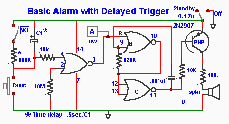
The first application is for a Basic alarm system with a delayed trigger.
The delay is set by R1/C1) for exemple , R1=680k and C1=10uf give a time delay of approx 8 secs. Thus time can adjusted by the choice of R/C values.This delayed trigger allows time to set the module in the "Standby" and exit within the time delay period before the alarm is triggered. Again on re-entering the alarm must be reset within that delay period . Gate A forms the trigger circuit and gates B&C form a tone generator of 800hz to the speaker activated by the transistor.
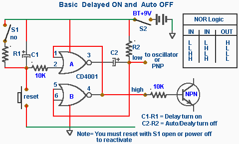
 In the next circuit in addition to the delay ON circuit we added an extra gate to provide for an auto/delayed turn off function. C2 & R2 are used to automatically turn off the alarm . Like C1 & R1 , C2 & R2 can be selected for the duration the alarm will stay on then automatically turned off. It must be reset to be reactivated. Two outputs are available as shown .
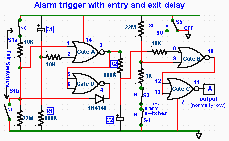
 But , the delay period may not be long enought to manually reset the unit . We can eliminate the guess work by integrating an auto-exit /entry delay that will not require a manual reset as shown in the next circuit.
 Functions
R1/C1 and R2/C2 forms the exit /entry delay ciruits . When the power is first applied (standby) all sensor switches (S3,S4) are enabled except S1a/b which is disabled for a pre-set period via time-delay network C1/R1 . At the end of this period S1 is automatically enabled . When S1 is activated the output of gate-A goes high and is locked by the action of D1 diode(1N4148) and gate-D. This high output voltage is applied to the input of gate-B via C2/R2 delay network an after a pre-set delay the voltage reaching gate-B rises to such a value that the alarm is activated.
Notes
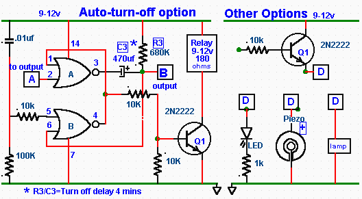
Add an auto turn-off option

|
© Laurier Gendron, Burnaby, B.C., Canada. 1999/mg