TECHNICAL NOTES
- VT2
|
TECHNICAL NOTES
- VT2
|
Herz, A., Airborne EM instruments operating at VLF and higher
frequencies in Airborne Resistivity Mapping, ed. G.J. Palacky; Geological
Survey of Canada, Paper 86-22, p. 55-61, 1986.
Abstract
Airborne VLF measurements are now commonly performed as a part of multiparameter airborne geophysical surveys. Present VLF instruments are light-weight, reliable, and easy to install and operate. Their addition to the airborne geophysical package increases only marginally the survey cost, yet the data are extremely useful in geological mapping. Total-field VLF data are usually presented as contour maps.
In the past, attempts have been made to conduct airborne resistivity mapping at VLF and higher (up to 1 MHz) frequencies. The E-PHASE was the first system capable of generating contour resistivity maps, but the lack of information at the lower end of the audio frequency spectrum prevented it from becoming a widely used airborne mapping tool.
Presently, airborne VLF systems are manufactured by three Canadian companies. The parameters measured differ slightly in each case. VLF sensors can be installed on a wing tip, nose stinger, lower helicopter frame, or a towed bird.
INTRODUCTION
Radio signals in the MHz range were used for geological mapping already in the 1930s, but at that time, only on an experimental basis (Cloos, 1934). Measurements at very low frequencies (VLF) ( between 15 kHz and 25 kHz ( became a practical exploration tool in the 1960s when Vaino Ronka designed the first portable VLF apparatus. The Geonics EM-16, as it was called, is a light-weight instrument (1.6 kg) which measures tilt angle and ellipticity of the magnetic component of the VLF field. The instrument is still in use and it has been consistently outselling other EM ground units. The VLF technique became practicable after the completion by the U.S. Navy and other powers of a network of powerful transmitters which were designed for communication with submarines. The VLF method, which does not require its own transmitter, could thus become the fastest and the least expensive EM technique. Another attractive feature of VLF measurements is the ease of theoretical solutions for a number of models. The plane-wave excitation is much easier to handle theoretically than dipole or large-loop sources.
EARLY AIRBORNE VLF SYSTEMS
The first operational airborne VLF system was developed by McPhar Geophysics Ltd. of Toronto in the early 1960s. It was called KEM and it used a pair of cross coils which measured horizontal-field strength and tilt angle. No measurements of the quadrature component were recorded. The instrument was rather simple and susceptible to errors in dip angle measurements, which resulted from pitch movement of the aircraft.
Geonics Ltd. of Toronto designed an airborne version of the successful EM-16. The instrument (EM-18) measured the vertical in-phase and quadrature components of the secondary magnetic field as a percentage and phase of the horizontal vector. A vertical gyro was used for correction of the aircraft pitch.
AIRBORNE RESISTIVITY MAPPING
The most ambitious VLF project was undertaken from 1969 to 1973 by Barringer Research Ltd. of Toronto. The company designed two airborne systems, RADIOPHASE® and E-PHASE®, which should have established the technique as an aid to geological mapping at par with magnetic and radiometrics.
The RADIOPHASE system used three orthogonal coils to measure the magnetic components of the magnetic VLF field and a vertical whip antenna to measure the vertical component of the electrical field. Because of its poor coupling with the ground, the vertical electrical component could be used as phase reference to correct the magnetic components for aircraft movement and variable transmitter intensity (Barringer and McNeill, 1970). Data were presented as vectors along profiles and contour maps of the in-phase component of the horizontal magnetic field. Anomalies were caused by surficial features (changes in overburden thickness), shear zones and bedrock conductors.
The second system, E-PHASE, was more widely used than RADIOPHASE and it was in use until 1979, Fifteen years ago, the existing AEM systems were not considered suitable for airborne resistivity mapping (Sinha, 1973) and the VLF techniques were thought highly promising for this task. The E-PHASE measures the in-phase and quadrature components of the horizontal electric field and the in-phase component of the vertical electric field. The ratio of the quadrature component of the horizontal electrical field and of the in-phase component of the vertical electrical field is called wave tilt. As Sommerfeld (1909) showed this quantity can be used to calculate earth resistivity.
As in galvanic resistivity measurements, one postulates apparent resistivity, which can be calculated for all measured points along the flight line. Measurements were carried out simultaneously at 3 frequencies, one in the VLF band (15 to 25 kHz), one in the LF band (200 to 400 kHz), and one in the MF band (550 kHz to 1.1 MHz). In the last band, non-directional radio beacons (NDB) located at airports or AM broadcast stations (BCB) were used. Three profiles of apparent resistivity were generated by digitally processing the raw data and resistivity maps were compiled for 3 frequencies. An example from a survey near Wadena, Saskatchewan, is shown in Figure 6.1. The three-frequency data could be used to interpret thicknesses and resistivities of up to 3 layers assuming horizontal stratification (Fig. 6.2). The E-PHASE scheme can be cited as the first successful application of digital data processing in AEM surveying. All operations were automated: digital recording, data correc tion, resistivity calculation, map gridding and plotting, and semi-automated inversion of the data to produce resistivity sections (Palacky and Jagodits, 1975).
While the E-PHASE was a technical success, it did not become one of the leading AEM techniques in terms of the mileage flown. In the context of this Workshop on Airborne Resistivity Mapping, it is interesting to note that the technique was marketed as "airborne resistivity". In the days when most efforts went into designing deeper penetrating AEM systems for massive sulphide exploration, the E-PHASE pursued the concept of a shallow penetration technique applicable primarily to Quarternary geological mapping. Numerous surveys in various parts of North America were successful in identifying lithological changes in shallow sediments.
PRESENT AIRBORNE VLF TECHNIQUES
The history of the last 20 years shows that VLF systems are viewed as a valuable accessory tool in multiparameter surveys, but are not accepted as a primary airborne geophysical technique. The demand is for reliable light-weight instruments that would be insensitive to changes in aircraft movement and remain virtually maintenance-free.
At present [circa 1986], airborne VLF systems are manufactured by Scintrex Ltd. and Herz Industries Ltd. of Toronto, and Sander Geophysics Ltd. of Ottawa. The Scintrex SE-99 is similar to the previously described Geonics EM-18, but in addition to the vertical magnetic component, it also measures the horizontal vector amplitude of the VLF magnetic field. The coils are compensated for aircraft pitch using level sensors. The Sander Geophysics VLF system has three orthogonal coils. A vertical gyro is used for aircraft movement compensation. Multichannel measurements are recorded and inflight processed by an onboard computer.
Herz Industries Ltd. developed two airborne VLF systems, Totem-1A and Totem-2A (Fig. 6.3). Both are light-weight and easy to install in an aircraft or a towed bird. Figures 6.4 to 6.6 show installations of the sensors on a wing tip and nose stinger (for fixed-wing planes) and a helicopter. While the Totem-1A was designed to operate at one frequency (operator selected), Totem-2A can simultaneously record VLF signals at two frequencies. This improvement is significant as it permits a better coverage using two transmitters. It is a known fact the conductors must point in the direction of the transmitter to produce optimum response. Other strikes result in degradation or even disappearance of VLF response. If the directions to the two transmitters are mutually perpendicular, good coupling with at least one can be expected, thus assuring a good coverage of the survey area. Totem-2A has three orthogonally mounted coils which measure the total field strength and the vertical quadrature component of the magnetic VLF field. No external correction is required for aircraft pitch, roll, and yaw.
The airborne VLF data are usually recorded digitally, and several sets of maps can be produced (2 quantities measured at 2 frequencies). Figure 6.7 shows total-field VLF data from Utik Lake, Manitoba. The survey area is located in a Precambrian greenstone belt, where iron-formations and graphitic conductors have been identified. Conductors appear as anomaly highs; on the example also the results of a helicopter EM survey are shown (circles indicating location of conductors).
CONCLUSION
The airborne VLF technique is widely used in airborne geophysical surveying.
Usually, it is an inexpensive add-on in multiparameter surveys. However,
the low cost does not imply low utility of the data. Hundreds of thousands,
perhaps millions of line kilometres of airborne VLF surveys all over the
world have demonstrated the usefulness of the technique in geological mapping.
Figure 6.1 Map of apparent resitivities obtained with the E-PHASE system near Wadena, Saskatchewan (frequency used 368 kHz). The shaded area indicates a gravel deposit found as a result of this survey (from Palacky and Jagodits, 1975).
Figure 6.2 E-PHASE response at 3 frequencies along Line 47 (indicated in Fig. 6.1). Interpretation of AEM data is shown for 2 anomalies, along with logs of 5 drillholes (from Palacky and Jagodits, 1975).
Figure 6.3 Totem-2A VLF receiver consisting of 19-inch rack-mounted
console, the receiving coils, preamplifier unit and interconnecting cables.
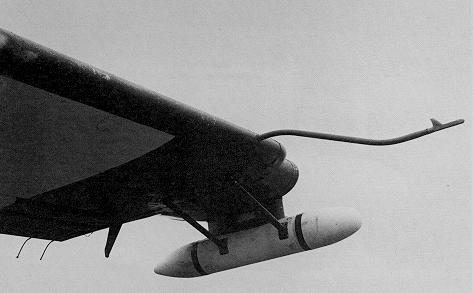
Figure 6.4 Wing-tip installation of Totem-2A receiving coils (courtesy of Geoterrex Ltd. of Ottawa)
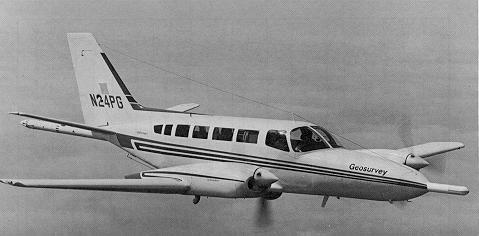
Figure 6.5 Nose-stinger installation of Totem-2A receivers (courtesy of Geosurveys International Ltd. of Nairobi)
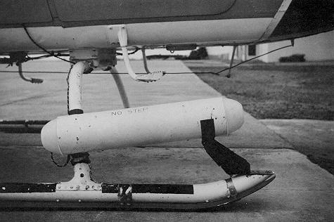
Figure 6.6 Helicopter installation of Totem-2A receivers (courtesy of Placer Exploration Ltd. of Vancouver).
Figure 6.7 Contour map of total field VLF response from Utik Lake, Manitoba. Also shown are locations of conductors obtained in the course of a helicopter EM survey (courtesy of Westmin Resources Ltd., and Dighem Surveys and Processing Inc. of Mississauga).
ACKNOWLEDGMENTS
I thank Geosurveys International Ltd. of Nairobi, Geoterrex Ltd. of Ottawa, and Placer Exploration Ltd. of Vancouver, for supplying photographs of their installations, and Westmin Resources Ltd. and Dighem Surveys and Processing Inc. of Mississauga, for examples of VLF surveys. G.J. Palacky of the Geological Survey of Canada provided information on the RADIOPHASE and E-PHASE systems.
REFERENCES
Barringer, A.R. and McNeill, J.D.
1970: The airborne RADIOPHASE system
- a review of experience;
72nd Meeting, Canadian Institute
of Mining and Metallurgy, Toronto
Cloos, E.
1934: Auto-radio als Hilfsmittel geologischer Kartierung;
Zeitschrift fur Geophysik, v. 10, p. 58-66
Palacky, G.J. and Jagodits, F.L.
1975: Computer data processing and quantitative
interpretation of airborne resistivity surveys,
Geophysics, v. 40, p 818-830.
Sinha, A.
1973: Comparison of airborne EM coil systems placed
over a multilayer conducting earth;
Geophysics, v. 38, p. 894-919.
Sommerfeld, A.N.
1909: The propagation of waves in wireless telegraphy,
Annals of Physics, v. 28, p. 665.
|
|
|
|
|
|
|
|