![]()
| Introduction | construction-1 | Construction-2 | Construction-3 | Calibration |
As a reference you may wish to open up a new window to view the circuit while on this page .Technical Info
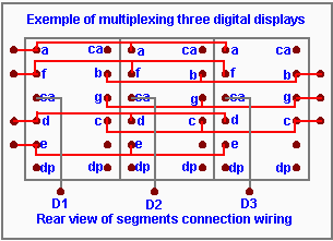
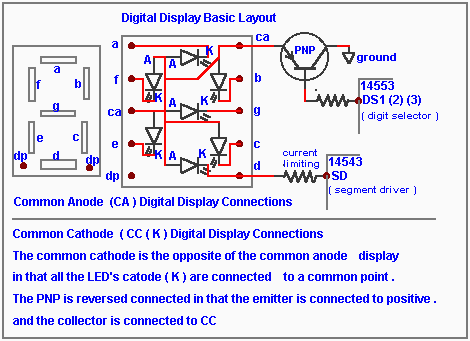
LED displays of all sizes and brightness are available , a best buy is to get a three to four digit stick that is already multiplexed . For those who are not familiar with their use I include some details and drawings for your information . Use lengths of about 3" of rainbow coloured #24 wires for easy identification as a harness and solder each end to the circuit board . Make sure you identify correctly which wire goes where .
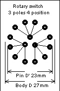
Details of the Rotary switch wiring is shown below . As an option two more ranges will be added when a SPST switch is used to parallel a 1.uF capacitor to the .1uF of range 3 &4 . If you install the rotary switch on the foil side don't forget to reverse the order of the resistances and capacitors on the switch . Also shown is the dimension of the switch to fit the PCB .
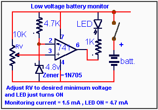
R1 and R2 form the calibrated set point voltage divider to pin # 3 of the 741 and can be replaced by a 10K variable resistance to calibrate for other voltages above 6 volts.
© Laurier Gendron, Burnaby, B.C., Canada. 1998
Introduction construction-1 Construction-2 Construction-3 Calibration
Home
If you have any comments or questions email me at roma60@home.com