![]()
| Introduction | construction-1 | Construction-2 | construction-3 | Calibration |
As a reference you may wish to open up a new window to view the circuit while on this page .
I have designed two models to choose from . One which I will call the WORKBENCH and the other the PORTABLE .
The basic design is exactly the same in both but the layout is different as shown . I have listed the differences in their appropriate window.
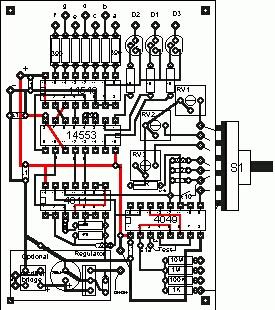
Work Bench Model is designed to be used with a side vertical mounted switch to allow very short leads to capacitors and other components to minimize noise and stray oscillation.
It also provide as an option PC layout for a regulated supply source.
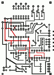
On the left is the PCB tracing . On the right is the PC Tracing with components overlay and suggested switch mounting .
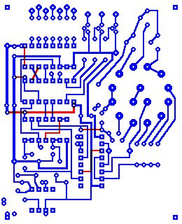
The Portable model shown on the right was designed so that the switch can be mounted directly on the PCB or hand wired board .
The switch is shown mounted on the components side .
A low battery voltage monitor circuit was added .
The switch on the Portable model can be installed on the foil side BUT remember to reverse the order of the switched component . Once this is done it is a simple matter to use a Ohmeter and check all wiring connections on the sockets pins , any error will be readily detected . I then apply power and check for any current that would indicate a short ,remove power ,insert the IC's one by one ,apply and remove power after each IC's while monitoring for excessive current .
Introduction construction-1 Construction-2 construction-3 Calibration
Home
If you have any comments or questions email me at roma60@home.com © Laurier Gendron, Burnaby, B.C., Canada. 1998