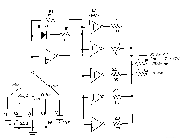

Component list:
R1       15 kohm
R2       150 ohms
R3-R7    220 ohms
R8       22 ohms
R9       47 ohms
C1       47 pF
C2       220 pF
C3       1 nF
C4       4.7 nF
C5       22 nF
D1       1N4148
IC1      74AC14
NOTE: Do not try to substitute IC1 with any other type of IC because the circuit does not work correctly if other 7414 IC type than 74AC14 is used (74HC14 and 74HCT14 do not work well).
This circuit is best powered with 4.5V battery or three 1.5V batteries connected in series. The + from battery goes to IC1 pin 14. The pin 7 of IC1 is connected to circuit ground which is connected to circut ground. Remeber to put a 100 nF (ceramic or polypropylene) capacitor between IC1 pins 7 and 14 to guarantee stable operating voltage for the circuit.
TDRs are used in all phases of a cabling system's life, from construction to maintenance and to fault finding. Historically, the TDR has been reserved for only large companies and high level engineers. This was due to the complexity of operation and high cost of the instruments.
If a cable is metal and it has at least two conductors, it can be tested by a TDR. TDRs will troubleshoot and measure all types of twisted pair and coaxial cables. TDRs can locate major or minor cabling problems including; sheath faults, broken conductors, water damage, loose connectors, crimps, cuts, smashed cables, shorted conductors, system components, and a variety of other fault conditions. TDR can be used to locate the problem type and in which place along the calbe the fault is.
The TDR works on the same principle as radar. When that pulse reaches the end of the cable, or a fault along the cable, part or all of the pulse energy is reflected back to the instrument. Any impedance change in cable will cause some energy to reflect back toward the TDR and will be displayed. How much the impedance changes determines the amplitude of the reflection. The TDR measures the time it takes for the signal to travel down the cable, see the problem, and reflect back. The TDR then displays the reflected signal as information on waveform display.
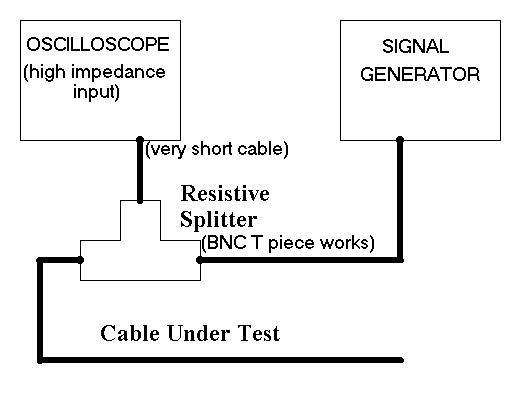
This circuit in this article is made to be used with a normal oscilloscope. The circuit which you build is used as the signal source and the oscilloscope is used as a waveform monitor. Connection diagram:

Many TDRs have selectable pulse width settings. The larger the pulse width, the more energy is transmitted and therefore the further the signal will travel down the cable. This circuit includes settings from 10 nanoseconds to 5 microseconds. Short pulses are ment to test short cables and to locate faults nearby. If the fault is very small or cable is very long, the signal strength of a small pulse may not be enough to travel down the cable, "see" the fault, and travel back.
When you look at the oscilloscope screen you first see the transmitted pulse and sometime after it you will see the reflected pulse. The second pulse has the following characteristics on different fault conditions:
Good sites to look for further information how to use a TDR: