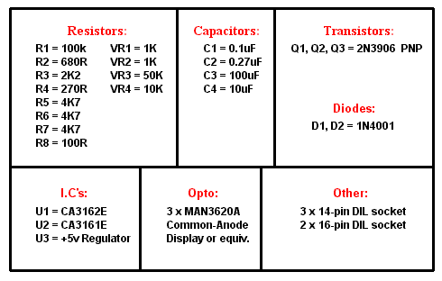
3-Digit Voltage Meter
|
Intro.
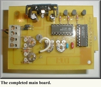
This handy little circuit was passed on to me from my good friend, Jim Lee - KF6K. The DVM is built on two seperate boards; the main pcb and a display pcb. It can replace any analogue d.c voltage meter.
I was lucky here because Jim sent me a complete kit of parts. So it made sense the DVM be adopted "The KF6Kit". |
Due credit to James W.Elkins - KA8PH0, for the original design. His version differed slightly in that the LED's on his display board were spaced too far apart for my liking... Ugly! I redrew the pcb's to not only have the LED's closer, but to make things easier when soldering both boards together. That said, the rest is pretty much the same as the original. |
 |
Some features of the KF6Kit:
- Reads 0 - 99.9 volts d.c.
- Voltage overload indication (shows "EE.E")
- Operates from 9V - 15V supply.
- Uses readily-available components.
- Easy to calibrate.
- Ready-made pcb's available from FAR Circuits.
|
|
The circuit.
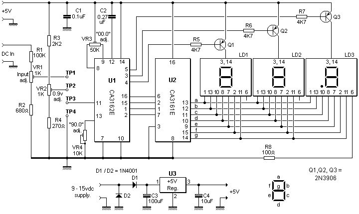
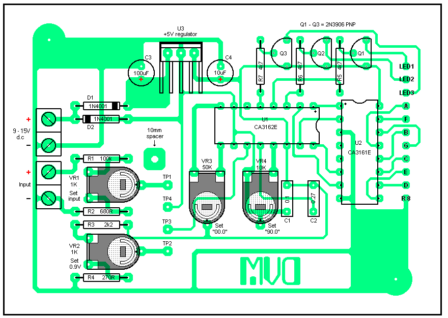
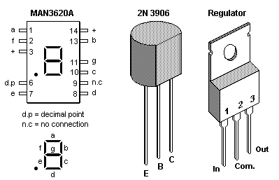
The circuit is based around the analogue-to-digital chip, U1 (CA3162E). The processed d.c input voltage is sent as a binary-to-decimal form to the display driver chip, U2 (CA3161E). The coded outputs of U2 (pins 9 through 15) then go on to the three common-anode LED's which are connected in a multiplex fashion.
Power is taken to the unit from a d.c source in the range of about 9 - 15 volts. This source is polarity-protected via D1 and D2 and then passed to the on-board voltage regulator, U3. This supplies +5 volts to the A/D and display driver chips and a voltage divider chain consisting of R3, VR2 and R4. VR2 is trimmed to give 900mV (0.9v) at TP2 which is used during calibration.
|
Resistors R1, VR1 and R2 serve to scale the input voltage to a level that can be safely used by the A/D chip.
C2 (0.27uF), is a critical component. This is used for timing purposes for the A/D chip and should be of a high-quality polyester type. Capacitors C1, C3 and C4 smooth and decouple any noise present on the supply. Transistors Q1, Q2 and Q3 are used as digit driver buffers along with their current-limiting resistors, R5 through R7.
Four on-board test points (TP1 through TP4) have been included to be used during calibration. |
|
Putting it all together.
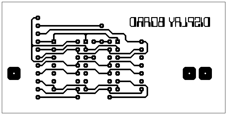
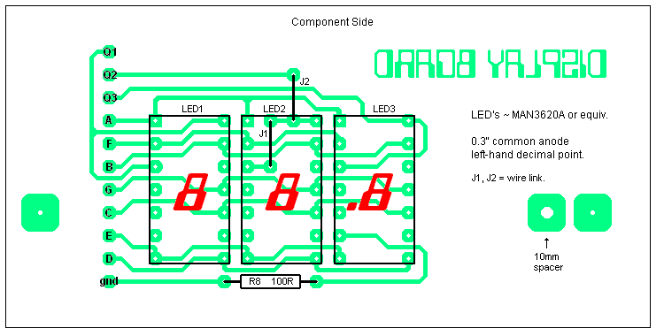
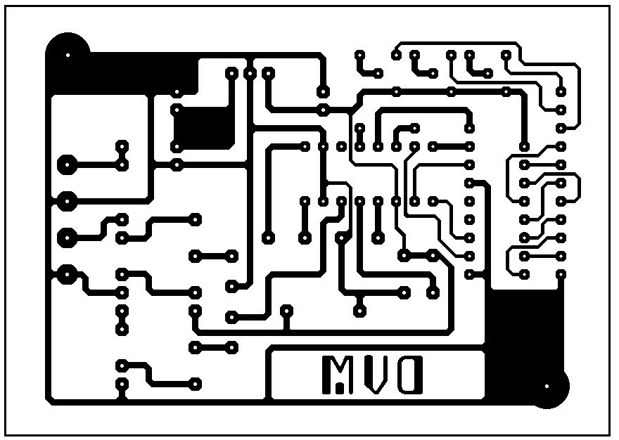
Since some pads on both pcb's are quite close, it's probably a good idea that you use a low-wattage iron with a fine tip. Start with the display board first. But, before you rush ahead, note that there are two wire links that need inserting before you solder the 7-segment LED's. Both of these links are under the center LED - a little difficult to do if the displays are soldered in first. Also, I recommend that you use 14-pin DIL sockets to accommodate the LED's. Should one fail it's then a simple matter of popping a new one in place. But do make sure that the LED's are inserted with the left-hand decimal point as shown. It's easy to get these wrong (as I did!)
The main pcb components can be soldered in any order you prefer, but I did it as... |
DIL sockets, resistors, trimpots, capacitors, diodes, transistors, voltage regulator (on heatsink), two 2-way screw terminal connectors, and finaly, the four off-board connection solder pins (TP1 - TP4).
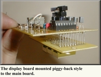
When you reach this stage, it's up to you to decide how you want to connect the two boards. Some homebrew'ers use ribbon cable. But, because I find this stuff difficult to work with, I opted have the boards placed back-to-back and interconnected with 11 resistor leads. From experience this is by far the easiest method. It's also a good idea to insulate these leads with sleeving. So why didn't I do that..? Because I didn't think of it until after they were soldered! |
|
You'll notice that the interconnection pads between both boards will align hole-for-hole. e.g: pin 1 to pin 1... pin 2 to pin 2, etc. Looking at the picture you can see where I've used the eleven resistor leads used to make the interconnections. A 10mm spacer was used between the relevant holes on both boards to hold them parallel before the resistor leads were soldered proper. The two outer holes on the display board are used to support the unit to a fascia panel with two 10mm spacers.
If you decide to use this method make sure to solder the resistor leads in the main board first. You'll find it much easier when it comes to soldering the opposite ends on the display board due to its slight overhang.
When you reach this point you'll probably be itching to power-up to see the LED's a-glowing... but WAIT!! Spend some time checking both boards for any unwanted dry joints and/or solder bridges. We've all made these mistakes at some time, so take your time to check things through. (I use a small magnifying glass for such purposes). |
 |
|
Calibration.
You'll need a digital or accurate analogue multi-meter to make the adjustments.
Before you insert U1 and U2, connect a supply between 9 and 15 volts d.c and check you have +5 volts after the regulator (pin 3). In the advent U3 should show anything much higher than +5 volts, this simple precaution will at least protect the chips from frying.
If all is well, insert U1 and U2 and follow this procedure...
- Set all trimpots to approx. mid-way position.
- Connect a 9 - 15vdc supply to the "+" and "-" terminals.
- Check the display is showing: "EE.E".
- Attach a test-lead with clips between TP3 and TP4.
- Adjust VR3 for zero reading ("00.0"). When done, disconnect the test lead.
- Connect your multi-meter "+" lead on TP2 and the "-" lead on TP4.
|
- Adjust VR2 for a reading of 900 millivolts (0.9V).
- Disconnect your multi-meter when this has been set.
- Attach the test lead with clips to TP2 and TP3.
- Adjust VR4 for "90.0" on the DVM display. Disconnect the test lead when done.
- Solder a short insulated length of wire to TP1 and TP3.
Finaly, connect a known voltage source to the d.c input terminals and adjust VR1 to have the display read this known voltage. The on-board regulator will serve as a voltage source here. If you connect the test wire between the "+" side of C4 and the top end of R1, adjust VR1 to read "05.0" on the display.
And that's all there is to it. |
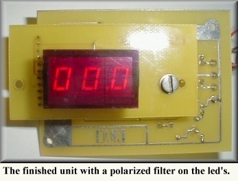 |
The finished unit shown here has a polarised filter robbed from an old CB radio placed over the LED's. As luck would have it, it fits perfectly on the display. Unfortunately, the flash on the camera doesn't do this picture much justice - the reality is a much sharper display than shown here.
I've also tried green 7-segment LED's...
...and I still can't make up my mind which color I prefer. |
If you wish to etch your own pcb's, here are the templates:
(See the page Resizing Your Artwork for the correct printout component spacing.)
...or if you prefer, ready-made PCB's are available from Fred at Far Circuits.
(Order quote : "Peter Keirle DVM".)
Full details are listed under Test Equipment and General Measuring Instruments.
|
Components.
Some constructors have been confused by the component notation I use in my circuits. European and American notation can and does differ. This holds true, for example, in the way that values for resistors are written. Since resistance is measured in Ohms, I simply write 'R' instead of 'Ohms'. For instance, a one-hundred-Ohm resistor is written as 100R.
The same rule applies to a resistance value of, say, 4,700R. A shorter way of expressing four-thousand (4,000) is to use 'K' (shortened from 'Kilo'). So our 4,700R resistor could be written as 4K7. And yet another way of expressing the same value could be written as 4.7K
4K7, 4.7K and 4,700R... each means the same value. |
And while we're on this subject, some of you ask where you can obtain components. Here in the UK I use various suppliers. You can find more details on the Links page under the heading, 'Suppliers'.
Maplin and RS (Radio Spares) are two major supplier here. Tandy is another good source, but sadly no longer trading in the UK. But since this hobby is about home-brew, you can find loads of cheap parts at local rallies, etc. Yet more sources of components are from old or broken equipment. Satellite receivers, radio's, TV's, Hi-fi's, etc... they all have something worth salvaging.
And since all my projects use ball-park components, you shouldn't have much problem finding 'em. |
KF6Kit resistor color codes:
| Value |
Band 1 |
Band 2 |
Band 3 |
Band 4 |
| 100K |
Brown |
Black |
Yellow |
Gold |
| 680R |
Blue |
Grey |
Brown |
Gold |
| 2K2 |
Red |
Red |
Red |
Gold |
| 270R |
Red |
Violet |
Brown |
Gold |
| 4K7 |
Yellow |
Violet |
Red |
Gold |
| 100R |
Brown |
Black |
Brown |
Gold |
Click here for more details of four-band
and five-band color codes.
| |
|
LED segment to U2 driver chip data:
| Segment: |
Pin#: |
To U2 pin#: |
| a |
1 |
13 |
| b |
13 |
12 |
| c |
10 |
11 |
| d |
8 |
10 |
| e |
7 |
9 |
| f |
2 |
15 |
| g |
11 |
14 |
| decimal point |
6 |
ground (via 100R) |
| |

Best Regards... Pete
http://www.keirle.fsnet.co.uk