Figure 1 - High Impedance
Attenuator ( > 2M Ohm)

| Elliott Sound Products | Project 16 |
When performing any tests on an audio system, some form of measuring device is essential. Digital multimeters are not useful, since they will not give the true picture of what is happening, and most have a fairly limited frequency range. An oscilloscope is the ideal tool, but not all hobbyists can afford the outlay for a scope, and would find justifying the not inconsiderable cost a tad difficult.
An AC millivoltmeter - calibrated in dB - with a range of 30V down to 3mV full scale (80dB range) would be extremely useful. Attach a microphone (electret mic capsules are quite good), and you have a relative sound level meter, even better if you have some way of calibration.
The meter presented here has a very wide frequency range, and uses a switched attenuator for range adjustment. The attenuator uses the 30-10-3 sequence, which provides 10dB steps between ranges. The standard attenuator provides an input impedance of over 2M Ohms, but is a nuisance because with such high impedances stray capacitance causes havoc with the calibration, so a parallel capacitive attenuator is also needed. If you expect to work with valve amplifiers, you will want the high impedance, but otherwise the low impedance attenuator should do nicely.
The two attenuator networks are shown in Figures 1 and 2, and as you can see the Hi-Z version requires all those capacitors. They must be accurate, too. Otherwise high frequency performance will be all over the place, so you need a capacitance meter or a source of close tolerance caps. The resistors are standard E24 series 1% metal film types, and the caps (if used) should ideally be polystyrene but if ceramic is all you can get, then ceramics are what you use.
Figure 1 - High Impedance
Attenuator ( > 2M Ohm)
With the Lo-Z attenuator, performance can be expected to be quite linear up to at least 80kHz before stray capacitance starts to influence the measurement. Without the paralleled capacitive attenuator, the Hi-Z version will start to show incorrect readings above 10kHz, which is unacceptable. The stray capacitance comes from the switch contacts and the proximity of the resistors to each other, and only a few pF will cause havoc at high frequencies.
To minimise capacitance, mount all resistors (and capacitors) directly off the rotary switch, and keep them as separated from each other and the remainder of the circuitry as possible. Do not be tempted to try to make the arrangement nice and neat (with all the components nicely aligned with each other), for this will increase the capacitance of the circuit and ruin the high frequency performance.
Figure 2 - Low Impedance
Attenuator ( > 200k Ohm)
The low-Z version is less succeptible to stray capacitance, but even at 150k (the highest value resistor in the circuit), only a few pF is needed to start to have an adverse influence at 100kHz or so. Again, do not strive for neatness, as this will only degrade performance.
As can be seen, both attenuators have the same ranges - from 3mV to 30V in 10dB steps. Because 10dB is a ratio of 3.16, the scale must be calibrated with two voltage scales, 0-1 and 0-3. If you are very fortunate, it may be possible to find a meter with these ranges already (I have used about 3 of them in various projects), but they are now rather scarce. We can blame digital technology for this, but some analogue multimeters might have the scales you need - such a meter will not be cheap, however.
Note: There were errors in the original diagram, the first showing a 220 ohm resistor where it should have been 150 ohms. This did nothing for accuracy :-( If using the scale suggested, all 4xx value resistors were also wrong - the correct values are now shown. My apologies for any inconvenience.
The amplifier(s) used in such a project are critical - we need wide bandwidth and low noise, coupled with low current drain, since we want to be able to run the meter on a 9V battery. The meter amplifier also requires high input impedance - especially for the high impedance attenuator version.
Consequently, a discrete opamp is the device of choice, since it can be built to satisfy all the desirable features we need. The input sensitivity of the meter amp is 3mV for full scale deflection on the meter, so it requires a fair bit of gain. In the final circuit, a JFET is used to provide the necessary high impedance input, and has the added benefit of supplying extra gain - this helps to reduce the demands on the opamp, since a typical 2N5459 JFET in the circuit shown (Figure 4) provides a gain of about 15, raising the input voltage to the opamp circuit to about 45mV for 3mV input.
Figure 3 - Basic Meter
Amplifier Scheme
Another requirement is simplicity and good linearity. The basic meter amplifier shown in Figure 3 satisfies all our requirements, but as you can see uses germanium diodes. Although these are harder to get and more expensive than silicon (and have higher leakage current), they also have very wide bandwidth and significantly less voltage drop than silicon, which reduces the requirement of the opamp to have an infinite slew rate.
This basic design has been around for many years, and is still one of the easiest to make, having the minimum of parts. The voltage across R2 must be the same as the input voltage (basic law of opamps) for the amp to be stable, so all losses in the meter and diodes are "restored" by the opamp. The capacitor will need to be selected for the meter movement you use, since different meters have different damping. Initially this can be left out, but if excessive meter swings cause problems (or oscillation at low frequencies), then the capacitor will be needed. A value of 10uF is always a good starting point.
The input sensitivity is simply set by changing the value of R2 (In Figure 3), with lower values providing higher sensivity and vice versa. Typically, R2 will be a multi-turn trimpot to allow for calibration.
The entire circuit can be built easily on a piece of perforated board (Veroboard or similar is good for this type of circuit), and a printed circuit board is quite unnecessary. Lay the physical circuit out following the schematic layout as closely as possible. This nearly always works well with discrete circuits, and makes it easy to follow 10 years later when you need to fix it. (I have had mine for nearly 20 years, and have not had to fix it yet.)
Figure 4 - The Complete
Meter Amplifier
Figure 4 shows the complete meter amplifier, and uses a 2N5459 J-FET for the input. This provides a very high input impedance as well as some useful gain (about 15), allowing the entire unit to use a single discrete opamp - a discrete design is used to obtain optimum performance (frequency response) not readily obtainable with standard opamps for this application. The distortion characteristics are relatively unimportant, but the requirement for wide bandwidth and high gain over the entire frequency range excludes most conventional opamps.
Note that the FET has no gate resistor, but relies on the voltage divider (attenuator) for its earth reference. This is not generally considered good practice, but will cause only minor "flicks" of the needle when changing ranges. Also be aware that there is minimal input protection, so if you have the meter set to the 3mV range and connect it to the speaker output of an amplifier, you will probably cause damage. A resistor (10k) in series with the gate is be used, but will not offer full protection. A resistor which would offer full protection at any voltage will also cause problems at high frequencies because of its high value. Likewise, the capacitance of protection diodes will also adversely affect the high frequency performance (which is why there aren't any).
The discrete opamp is only a simple design, but manages a frequency response to well over 100kHz (-1dB) with the 50uA meter load, and will operate satisfactorily with battery voltages down to 8V (the lower limit for a 9V battery before its internal impedance rises significantly). 100uF capacitors are used to ensure that the battery supply is bypassed, to help counteract the impedance rise as the battery ages.
I used BC549 (NPN) and BC559 (PNP) transistors, but any high gain, reasonably wide bandwith, low current device will (should) work fine. As always, all resistors should be metal film, and the two pots should be multi-turn to allow accurate setting.
The initial test involves connecting the meter amp to the attenuator, and applying power. All wiring must be carefully checked before you do this - the 9V batteries can supply enough current to damage the transistors, but batteries are more expensive than the transistors, and a wiring mistake may place a heavy discharge on the batteries rendering them dead before their time. Normally, batteries should last for quite a while, since the current drain is only about 4.5mA.
The meter is provided with protection by D5, a 1N914 (or 1N4148) which will conduct if too much voltage (or current) is applied - the meter will be hard against the stops though, and may still be damaged if the condition is allowed to persist. When power is applied, the meter should flick to full scale, then quickly settle back to near 0 volts. If it remains at full scale, you have made a mistake, so remove power immediately and locate (and fix) the error.
Calibration involves first setting the Set 0V Offset pot to its midway position, then carefully adjusting until the meter reading is as close as possible to the zero voltage mark. Any remaining offset must be removed using the meter's mechanical zero adjustment - this is a little crude, but there is not much choice with this type of circuit. You will find that the meter reading will drop to some minimum value then start to climb again - this is because of the full-wave rectifier in the meter and feedback circuit.
Next, an accurate voltage at somewhere between 100 to 2,000 Hz is used to calibrate the meter. Select a suitable range on the attenuator, then adjust the Sensitivity control until the meter shows a reading that is identical to the applied voltage. Where possible, this should be done with the millivoltmeter at full scale on the 1V range. Remember that the scales are different for 1V and 3V ranges. The sensitivity pot will have more than enough range to allow the unit to be calibrated, provided no wiring mistakes have been made.
If by some chance your version decides it wants to oscillate at a MHz or three, you will need to add a small capacitance between collector and base of Q4 - I would not expect that more than 10pF should be needed, and even this will reduce the high frequency response slightly. Mine has a -1dB upper frequency limit of about 250kHz, a frequency which is more than adequate for audio use (by nearly an order of magnitude), but this is without a frequency limiting (miller or dominant pole) capacitor.
It is important to obtain the best meter movement you can find, or the unit will be hard to read and possibly inaccurate. You will need to make a new scale for the meter, showing the two ranges and a dB scale. One possible reproduction is shown below, and there are links to a couple of others, one of which should suit whatever passes for a fairly standard 50uA movement - these should be available wherever you are, but you might need to look around a bit.
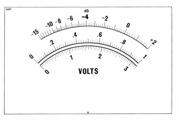
Figure 5 - Meter Face
The alternate meter faces are Meter Face 1 and Meter Face 3 - One of these should be able to be resized to suit the movement you use, but some experimentation is needed. You will notice that #3 appears to be hand-drawn in some areas - that's because it was. This is a scan from my own millivoltmeter, and when it was built, all these new-fangled scanners and computer thingies were a bit less common than today (you can gather from this that I have had the meter for a while).
To see what you are trying to find, check out this link to an Australian company called Jaycar Electronics. This is a link to the company website, and you will have to search for the movement (I used to have a link to the picture of the meter itself, but Jaycar has changed it website and that no longer works). Those available are not great meter movements, but are similar to the one I am using, and works quite well.
A typical 50uA movement will have a resistance of around 2k to 3k Ohms, and on average, expect to pay about AU$20 (or about US$15 or so) for a passably good movement.
When completed, the meter can be calibrated against a known accurate digital multimeter, using a frequency of about 100Hz (most digitals will give an accurate reading at this frequency).
If you would like to be able to measure the battery voltage without dismantling the instrument (I feel that this is a worthwhile addition), the switching shown in Figure 6 can be added. Note that both terminals of the meter must be switched, and the average of the two 9V batteries can be read on the 1V scale (so 0.9V would indicate 9V for each battery.
Figure 6 - Optional Battery
Check Circuit
Use of a trimpot - preferably multi-turn - allows the "voltmeter" to be calibrated against an accurate multimeter, and the voltage shown is with the meter electronics switched on, so it will read the real loaded voltage. Both batteries are measured in series, so the nominal voltage read by the meter is 18V (R=18/50uA=360k, so a 1M trimpot should be near the middle of its travel). This option requires that the power switch be a 3-position 4-pole rotary, so it will cost a little more than a simple DPST mini-toggle.
WARNING: Make sure that the trimpot is set to approximately 1/2 way before attempting calibration of the voltmeter. 2 x 9V batteries will destroy the coil of the meter instantly if the pot is set at minimum!
The case used must be all metal, since the attenuator and meter amplifier needs good shielding against noise pickup. This can be made from sheet aluminium or other metal (steel, brass, etc) if you have the tools to work with it, otherwise a suitable case may be obtainable from your normal parts supplier.
Another alternative is to use un-etched copper clad printed circuit board. Cut the panels to size, and solder together from the inside, filing off the outsides so the panels are all flush, and finally finishing the unit with a suitable coat or two of paint. There are many different finishes available in spray cans, so take your pick.
Cases built in this way can look surprisingly good if you take the time to finish them off well.
Make sure that the 0V line (the junction of the batteries, bottom of the attenuator string and earth input terminal are all tied to a common point on the front panel, and that the remainder of the case is in good electrical contact. If the case is not earthed properly, this is worse than using a non-shielded case!
It may also ne necessary to add shielding between the FET stage and the main meter, and a small cap (10nF should be connected across the meter output, as close as possible to the diodes. Keep all leads short, and ensure that the output leads are kept well away from the input.
The meter amp is wide band, and has a full scale sensitivity of 3mV. It will oscillate if there is any feedback from O/P to I/P or between stages.
Drill all holes first for the two rotary switches, the meter and its mounting bolts and the input connectors. I always use a BNC connector, but for audio an RCA connector might be better. One can also use "banana" sockets, so you can use ordinary multimeter leads, but being unshielded they will pick up noise - especially on the lower voltage ranges.
Make sure that all panel components fit properly, and de-burr the panel on both sides.
Mark the switch positions for each setting very carefully, since markings that do not line up with the pointer on the switch knobs look tacky, and can be confusing when you use the instrument.
Once you have the exact switch positions marked out, the front panel can be labelled any way you see fit. One method that works well is to use a graphics drawing package to create the label, and print it out onto ordinary paper. Carefully stick clear "contact" film (as used for covering school books, etc) on both sides, ensuring that there are no air bubbles trapped under the film. Trim to the exact size of the front panel.
Use spray adhesive on both the panel and the label, leave for a few minutes then very carefully apply the label. You have to get this right first time - once stuck you will damage the label trying to move it ! The hole cutouts should then be very carefully removed using a hobby knife, scalpel or other suitable (sharp) instrument.
That's it - you are now the proud owner of a very useful piece of test equipment.
| Copyright Notice. This article, including but not limited to all text and diagrams, is the intellectual property of Rod Elliott, and is Copyright (c) 1999. Reproduction or re-publication by any means whatsoever, whether electronic, mechanical or electro-mechanical, is strictly prohibited under International Copyright laws. The author (Rod Elliott) grants the reader the right to use this information for personal use only, and further allows that one (1) copy may be made for reference while constructing the project. Commercial use is prohibited without express written authorisation from Rod Elliott. |