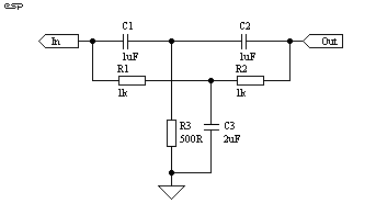
Figure 1 - Basic "Twin
T" Notch Filter

| Elliott Sound Products | Project 52 |
Total harmonic distortion (THD) measurements are one of the most commonly quoted in audio. Contrary to belief in some circles, these can be very useful if performed properly, and reveal much about the overall performance of an amplifier.
There are a number of ways to measure distortion, none of which is perfect. Probably the best is a spectrum analyser, which shows the individual harmonics and their amplitudes. These are too expensive for the likes of you and me (well, me, anyway) and the next best thing is featured here.
There are other methods as well, one of which is to subtract the output of an amplifier from the input (with appropriate scaling). When the two signals are exactly equal and opposite they are cancelled out - any signal left is distortion created in the amplifier. This method seems easy, but is not, because there are phase shifts within the amp that can be very difficult to compensate for exactly, and the final accuracy of tuning the parameters - amplitude and phase - must be just as great as with this circuit for a meaningful result.
The standard tool for measuring THD is a notch filter. This is tuned to reject the fundamental frequency, and any signal that gets through is a combination of the amplifier's noise (including any hum) and the distortion. The distortion shows up as a signal that is harmonically related to the signal fed into the amp, but is not the fundamental. Harmonics occur at double, triple, quadruple (etc) the input frequency. These are referred to as 2nd, 3rd, 4th (etc) harmonics, and are subdivided into odd and even. Even harmonics (2nd, 4th, etc) are claimed to sound better than odd (3rd, 5th, etc), but in reality we don't want any of them.
Figure 1 - Basic "Twin
T" Notch Filter
The filter of Figure 1 is "normalised" to 1uF and 1k Ohm, giving a frequency of 159Hz. The resistor and capacitor ratios are extraordinarily critical if a deep notch is to be obtained, and this is essential for distortion measurement. This notch filter is called a Twin-T, and works by phase cancellation of the input signal. When the phase shift is exactly +90o and -90o in the two sections, the tuned frequency is completely cancelled, leaving only those signals that are not tuned out. This residual signal represents total harmonic distortion + noise.
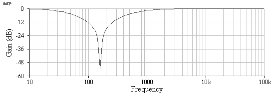
Figure 2 - Frequency
Response Of Standard Notch Filter
The problem with the notch filter shown, is that it's attenuation is too high at the 2nd harmonic, and in fact is only acceptable one decade from the fundamental. The example shown has about 0.7dB attenuation at 1.6kHz - a decade from the 159Hz fundamental frequency. This is corrected by using feedback, which tries to get rid of the notch, but is completely unsuccessful, since when properly tuned the notch is infinitely deep.
Too much feedback, and the filter will be untunable because it is too sharp, so a compromise is needed. We need the filter to cause no more that a dB or so of attenuation at double the fundamental frequency (this is one octave), to prevent serious measurement errors of second harmonic distortion.
Figure 3 shows the result when we apply feedback, and the error at one octave is now less than 1dB. This is acceptable for normal measurements, and the resulting error is small, while retaining the ability to tune the filter. Note that although it is tuneable, this filter is still extremely sharp, and unless multi-turn pots are used it will be almost impossible to obtain a good notch. The slightest variation of the input frequency will create a massively high "distortion" figure. I have found that with very low distortion amps, it is a real battle to measure the distortion whilst trying to keep the filter tuned, because of drift.
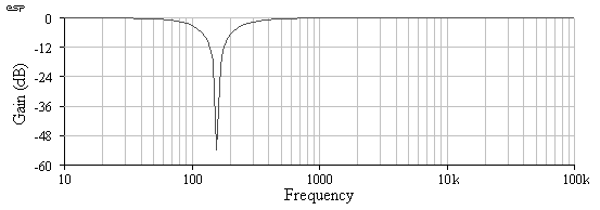
Figure 3 - Frequency
Response With Feedback
This overall characteristic is the desired one, so the final notch filter design is shown in Figure 4, with the feedback applied from the opamp. I have chosen to make the feedback adjustable, so that you can easily modify the characteristics if you want to. This can make it a little easier to tune, since initial tuning can be done with a small amount of feedback, and as the exact frequency is tuned in, the feedback can be increased.
Once upon a time, it was possible to obtain 50k+ 50K+ 25K wirewound pots (I think that was the range) - yes, a triple gang, two separate resistances, wirewound pot! These were especially for just this type of circuit, but I doubt that you will find one any more. The only way that multiple frequencies can be tested is to use a switched selector, and ensure that there is enough range in the tuning pots to make up for all capacitor value errors.
The accuracy of tuning is critical - a 40dB deep notch will show the distortion as 1%, even though it may be much less. A 60dB notch reduces this to 0.1% and so on. For a 100dB notch, you will need all components accurate to within 10ppm (parts per million), or 0.001%. Even a small temperature change can send the meter needle (or oscilloscope trace) straight off the scale. I know this, because it happens every time I try to measure very low distortion levels, and I can't even get to 0.001% on my meter because my oscillator has more distortion than that.

Figure 4 - The Variable
Q Tuneable Notch Filter
To change ranges, we must vary either the resistance or capacitance
(or both). Figure 5 shows the range switching. To try to keep
the unit reasonably versatile, I have included two switches. SW1
gives 20, 200 and 2kHz ranges by changing capacitor values. SW2 gives
the standard 1, 2, 5 sequence common in oscilloscopes. This combination
allows the following frequencies to be tested
| Range 1
(SW1) |
Range 2
(SW2) |
Frequency |
| 20 | x1 | 20Hz |
| 20 | x2 | 40Hz |
| 20 | x5 | 100Hz |
| 200 | x1 | 200Hz |
| 200 | x2 | 500Hz |
| 200 | x5 | 1kHz |
| 2k | x1 | 2kHz |
| 2k | x2 | 4kHz |
| 2k | x5 | 10kHz |
The notch frequency is determined by
fo = 1 / 2 * pi * R1 * C1The tuning requires that the ratios are exactly tuned - absolute values are not as important, but must be stable. To be able to tune the notch precisely, we will use pots in series with two of the resistors, R1 and R3. The range of the pots will vary depending on the resistance that is switched into the circuit, and even with multi-turn pots it is useful to have two in series, one with a lower resistance than the other. This is shown in Figure 5.
Resistor values are exactly R1 = R2, R3 = 0.5 * R1
Capacitor values are exactly C1 = C2, C3 = 2 * C1
It is essential to make sure that the pots have enough range to compensate for the tolerance of the capacitors, and some care is needed to keep wiring capacitance to a minimum, especially for the highest frequency range. To this end, I suggest that all tuning components are wired directly to the switches and pots, and that wiring is done with solid tinned copper wire. All wiring can be made self supporting, and will exhibit very low capacitance.

Figure 5 - Input Level
Control And Range Switching
The range switching simply connects different resistors and / or capacitors into the circuit. A problem is that when resistances are changed, the sensitivity of the tuning pots also changes. This is unavoidable unless you can get odd value triple-gang pots (Do you feel lucky? - If you find them, buy a lottery ticket !!). VR4 and VR6 should be multi-turn - you can get geared pot drives to use standard pots if multiturn units are unavailable.
The values and exact design frequencies are shown in Table 2.
To make the C3.x values, parallel two C1.x value caps, and if possible
use a capacitance meter to match all capacitors to within 1%. Standard
tolerances will affect the centre frequencies. Resistors must be
metal film, 1% tolerance. The values of R2.x and R3.x are lower than
expected, because I have taken the mid resistance of the two series pots
into consideration. Note that some of the resistors require 2 components
in series to get the desired resistance.
| Frequency | C1.x C2.x | C3.x | R1.x | R2.x | R3.x |
| 19.4 Hz | 100nF | 200nF | 82k Ohm | 75k + 4.3k | 39k + 1k |
| 40.8 Hz | 100nF | 200nF | 39k Ohm | 36k | 18k + 390 Ohm |
| 99.5 Hz | 100nF | 200nF | 16k Ohm | 13k | 6.8k + 100 Ohm |
| 194 Hz | 10nF | 20nF | 82k Ohm | 75k + 4.3k | 39k + 1k |
| 408 Hz | 10nF | 20nF | 39k Ohm | 36k | 18k + 390 Ohm |
| 995 Hz | 10nF | 20nF | 16k Ohm | 13k | 6.8k + 100 Ohm |
| 1.94 kHz | 1 nF | 2nF | 82k Ohm | 75k + 4.3k | 39k + 1k |
| 4.08 kHz | 1 nF | 2nF | 39k Ohm | 36k | 18k + 390 Ohm |
| 9.95 kHz | 1 nF | 2nF | 16k Ohm | 13k | 6.8k + 100 Ohm |
There are a couple of things to be aware of with this circuit. Firstly, the input impedance is quite low, and use of a buffer is not recommended because this will introduce additional noise and distortion. The opamps used for the feedback should be the best you can get hold of. The Burr-Brown OPA2604 is an excellent choice, with 0.0003 distortion and low noise. Other devices that will be suitable include the LM833 or the venerable NE5532.
To allow power amps to be tested, an input level control is needed, and this is also used for calibration. The control ideally should be a wirewound device, since power dissipation could be quite high, and wirewound pots add less noise than carbon.
The ideal measuring meter is an oscilloscope, but a millivoltmeter may be used. Without the oscilloscope you will be unable to see the "quality" of the distortion components, but use of an amplifier will allow you to listen to the residual - make sure that you have a limiter circuit on the amp, or a slight bump of the oscillator frequency control will blow your head off! A suitable limiter is published as Project 53.
The final measurement will include the distortion from the audio oscillator, and it is likely that this will be greater than that of many amps. It is not really possible to tell you how you can subtract this from the measured distortion, since the distortion waveform has a huge influence over the result. The distortion waveform is very important - a low average level spiky waveform (typical of crossover distortion) will sound much worse than an apparently higher level of "clean" 3rd harmonic distortion from a well designed push-pull amplifier stage.
THD% = ( V2 / V1 ) x 100 Where V1 is the initial voltage and V2 is the lowest reading
THD = ( 0.007 / 3 ) x 100 = 0.23%
| Remember that if you apply too much signal to the input, you will destroy the opamp. The use of protection diodes is not an option (IMHO), as this will introduce distortion, making your measurements useless. The distortion introduced by the analyser will exceed that of a good amplifier. This is unhelpful! |
The circuit can be simplified. For example, you may feel that there are more ranges than you need, and these can be adapted for your needs. You might even think that a single range is sufficient, and for many basic tests this is OK. Naturally, you will be unaware of distortion that may become apparent only at low or high frequencies - but I shall leave this up to you.
| Copyright Notice. This article, including but not limited to all text and diagrams, is the intellectual property of Rod Elliott, and is Copyright (c) 1999. Reproduction or re-publication by any means whatsoever, whether electronic, mechanical or electro- mechanical, is strictly prohibited under International Copyright laws. The author (Rod Elliott) grants the reader the right to use this information for personal use only, and further allows that one (1) copy may be made for reference while constructing the project. Commercial use is prohibited without express written authorisation from Rod Elliott. |