Last update, Wednesday,
September 26, 2001
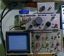
This part of the web page deals with the spectrum analyzer that Terry White (K7TAU) and I described in QST for August and September of 1998, and the related Tracking Generator appearing in November 1999.

The complete article is now available to be viewed and downloaded in PDF format from ARRL. Go to the ARRL web page and do a search on spectrum analyzer. This will then get you to a point where the two part paper can be downloaded.
Regarding the monolithic crystal filters: Mouser Electronics
lists the 520 -107-15B as a four pole filter. This is actually two
2-pole filters sold as a unit. See the Kanga page for information
on using these filters in the spectrum analyzer.
New IF and Log Amplifier (Sept 26, 2001)
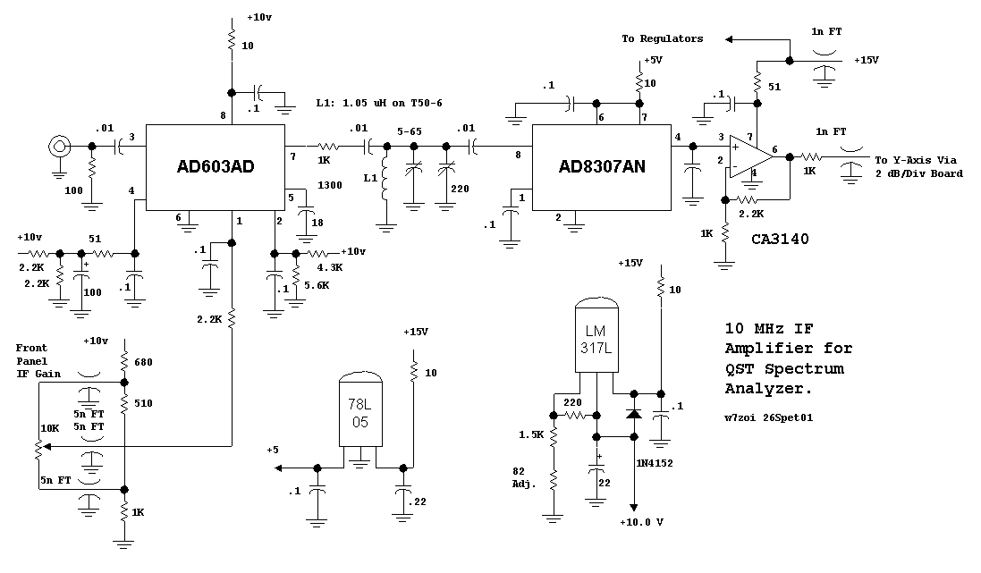
The original article presented data on a variety of integrated circuits that would function in the log amplifier. The Motorola MC3356 was the featured part, for it was available at the time we wrote the paper. The AD8307, which was still in a pre-production phase, was yet to become available. It is now available and is a far superior part. Hence, we dropped it into the analyzer. While doing the design work, we decided to try a new variable gain IF amplifier as well, the Analog Devices AD603. The overall circuit is shown below.

The IF gain gain will be from 10 to 50 dB, depending on the setting of the control pot. This pot is on the front panel of our analyzer. This circuit replaces the circuitry in Fig. 5 in the original article. The circuitry is built on a scrap of circuit board material mounted inside a Hammond 1590B box. The box output drives R2, the "log amp cal" pot, which then is routed to the added 2 dB per division board and then to the oscilloscope Y axis.
The board can be checked out before installation in the analyzer. A DC voltmeter is attached to the output and a 10 MHz signal is injected at the input and the tuned circuit is peaked. The maximum output should be around 5 volts DC with an input signal of about -28 dBm. The alignment should happen at 10.7 MHz if this is used in your analyzer. It may be necessary to adjust the resistors related to the LM317L regulator to obtain an output close to 10.0 volts.
The new log amp and IF is then dropped into the spectrum analyzer. Alignment is again straight forward. A calibration signal of -30 dBm is applied to the analyzer input at 14 MHz and the analyzer is tuned to see that signal. The Log gain should be near maximum. The IF gain pot and the vertical position on the 'scope are tweaked to put the response at the top of the screen at the "Reference Level." Then, the attenuator is used to reduce the signal in 10 dB steps. Ideally, the on screen response should move down at 1 major division for each 10 dB step. It will probably move more than that. If so, reduce the log gain a little and increase the IF gain to again calibrate the instrument at the reference level. Keep repeating the process until you get a good match to the response on screen. It will be amazingly accurate with this AD8307 Log Amp IC.
Once the basic calibration is done, you will see that the IF gain and the vertical position can both be adjusted to move traces around. By moving toward highest IF gain with a downward oscilloscope offset, you will get the maximum on screen range. Leave enough gain adjustment left to take care of the narrower filter bandwidth when it is switched in . The noise floor is an indicated -98 dBm when in the 300 kHz resolution bandwidth position with my analyzer, set for a -30 dBm reference level. It is possible to set the instrument up for a -20 dBm reference level, which is more convenient for some measurements. This analyzer could use a little bit more gain before the resolution filters to improve the noise performance.
The AD603 and the AD8307 integrated circuits were purchased from the Analog Devices web site. The '8307 arrived right away, but the '603 took several months. Hopefully the parts are now available "off the shelve."
If you don't want to use the AD603, the amplifier portion of the original circuit can be adapted. A bit more gain may be needed, which could be added with a simple feedback amplifier.
We have removed the details of the project from this page, but it is all still available at the Kanga web page, http://www.bright.net/~kanga/kanga/w7zoi_sa.htm
Many thanks to all the builders who have offered feedback.
To return to our HOME page, click "back" or www.easystreet.com/~w7zoi/