[
 Producing wound components]
[ Air coils]
[A guide to the terminology used in the science of magnetism]
[ Power loss in wound components]
[ Faraday's law]
Producing wound components]
[ Air coils]
[A guide to the terminology used in the science of magnetism]
[ Power loss in wound components]
[ Faraday's law]
See also ...
[
Producing wound components]
[ Air coils]
[A guide to the terminology used in the science of magnetism]
[ Power loss in wound components]
[ Faraday's law]
When the coil current increases so does the
magnetic field strength, H. That, in turn, leads to an increase in magnetic flux,  . The increase in flux
induces a voltage in the coil. It's the power
needed to push the current into the coil against this voltage which we now
calculate.
. The increase in flux
induces a voltage in the coil. It's the power
needed to push the current into the coil against this voltage which we now
calculate.
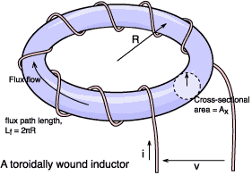 We choose a toroid because over its cross-sectional area, A, the flux density should be approximately uniform
(particularly if the core radius is large compared with it's cross
section). We let the flux path length around the core be equal to Lf and the cross-sectional area be
equal to Ax. We assume that the
core is initially unmagnetized and that the electrical energy (W) supplied
to the coil will all be converted to magnetic field energy in the core (we
ignore eddy currents).
We choose a toroid because over its cross-sectional area, A, the flux density should be approximately uniform
(particularly if the core radius is large compared with it's cross
section). We let the flux path length around the core be equal to Lf and the cross-sectional area be
equal to Ax. We assume that the
core is initially unmagnetized and that the electrical energy (W) supplied
to the coil will all be converted to magnetic field energy in the core (we
ignore eddy currents).
W =  v×i dt joules
v = N×d/dt volts
W = N(d/dt)i dt
W =  N×i d
N×i d
W = H×Lf d
= Ax× B so d = Ax×dB. Substituting:
W =  H×Lf×Ax dB joules
| Wd = H dB
joules m-3 |
Equation EFH |
Wd = B/µ dB
| Wd = B2/(2µ) joules m-3 | Equation EFB |
WL = L×I2/2 joules
Another squared term, you notice.[Top of page]
Uniform magnetic fields
A 'hand-waving' explanation might help clarify the physics. Take an
initially uniform magnetic field in free space and introduce into it an
iron sphere. The flux lines will bend in the
vicinity of the iron so that they will converge upon it. Inside the iron
the lines will be quite concentrated (though parallel to the original
field).
Now, the point is that there will be no net force on the iron, no matter how strong the field. A sphere has perfect symmetry, so rotation will not change the picture in any way. If there is translational movement then all that can happen if the sphere were to move is that the distortion of the field around the original position of the sphere will disappear and the same distortion will be re-established around the new new position; the total system energy will remain unchanged.
OK, instead of the sphere let's try an iron rod. This is different because we've lost symmetry. What happens is that the axis of the rod will be drawn into alignment with the field - like a compass needle. The flux lines prefer the iron to the air because of the higher permeability. Equation EFB has µ on the denominator so the field energy is lower here than in the air, and the further the flux can go through the iron the lower the energy. Think of current flow through a resistor; the current has an easier time going through a low resistance than a high resistance. Flux goes easier through high permeability than through low. When the rod is aligned with the field the flux can go further through a high permeability region. Note that we still don't have a translational force (provided that the field is uniform on the scale of the rod). Think about the famous experiment with iron filings sprinkled onto a piece of cardboard above a bar magnet. The filings tend to line up with the field but don't generally move much because they are so small that the field appears uniform to them.
So for there to be a force on a piece of iron then a displacement of the iron must result in an alteration to the field energy. The electromagnet you are using will have an opinion about changes to the field it generates. It will say that its inductance is changing. This is the basis of one solution to the problem:
| F = (I2/2)dL/dx newtons | Equation EFS |
[Top of page]
A simple experiment with a solenoid
A 'solenoid' is the term used to describe the type of electromagnet supplied with
an iron piston or plunger pulled in by the field generated by current in a coil.
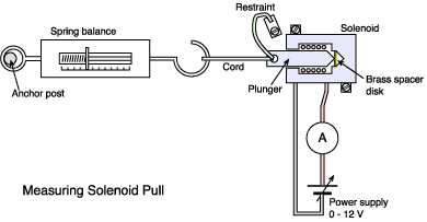 Solenoids are frequently used to operate
valves, release locks or operate ratchets and so on. Equation EFS above suggests that the pull of a solenoid
should be related to the square of the coil current. Take a medium
sized 12 volt solenoid (having a plunger about 13 mm diameter) and test
this out by attaching it to a spring balance as shown in the figure here.
Measurements are made as folllows:
Solenoids are frequently used to operate
valves, release locks or operate ratchets and so on. Equation EFS above suggests that the pull of a solenoid
should be related to the square of the coil current. Take a medium
sized 12 volt solenoid (having a plunger about 13 mm diameter) and test
this out by attaching it to a spring balance as shown in the figure here.
Measurements are made as folllows:
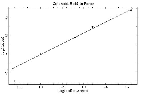
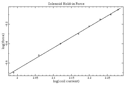
It would be nice to extend this experiment by a measurement of coil inductance against force in order to test Equation EFS. The difficulty is that inductance meters use AC test signals. Without laminated iron (which is only found in solenoids designed for AC operation) the reading will be affected by large eddy current losses.
[Top of page]