designed by Jap in December, 1999
improved in Jan. 2001
NOTE for beginners: PICs are general purpose microcontrollers which have to be programmed before you can use them in the actual circuit! Check out this link to learn more.
I finally got some small 433MHz radio transmitters and receivers and I needed an encoder/decoder circuit to make use of them for controlling equipment remotely. One could realize this by using Motorola MC145026-8 integrated circuits as well, but they need space and a few external components that must be calibrated by the user. Not to mention the challenge of creating an encoder/decoder by myself in software.
The encoder/decoder parts are to be connected to a transmitter/receiver module which takes care of the transmission of digital signals by radio or infra waves. The communication signal format is designed to be used for radio transmission (it has a constant 50% signal/silence ratio), but it can work with infrared devices as well. The transmitter has a varying number of buttons and sends the states of these inputs to the receiver. The receiver device decodes the message and sets the outputs accordingly. There are two protocols in the sources: the older version V2 represents digital 0 and 1 as different frequency pulses (800 and 1600 Hz), while the newer V4 outputs standard Manchester code (400/800 Hz). I recommend using the Manchester versions as the max. generated frequency is lower and the reception is more stable even with low speed or timing-inaccurate transmission channels.
As the source is available, you can combine the various parts of code toghether to design a system that fits your needs. Please note that all the devices have a device ID, which has to be the same between a transmitter and a receiver! This is not the PIC ID stored in a separate area of PIC but a software ID stored in the program area. It is encoded in every transmitted packet and checked to match by the receiver to identify matching transmitters & receivers.
All the files are provided here without any warranty. Please verify operation first by compiling the sources for flash parts. The sources you see here are proven working in several devices, still if you would find an error, please notify me!
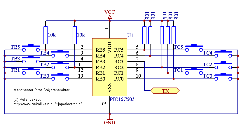
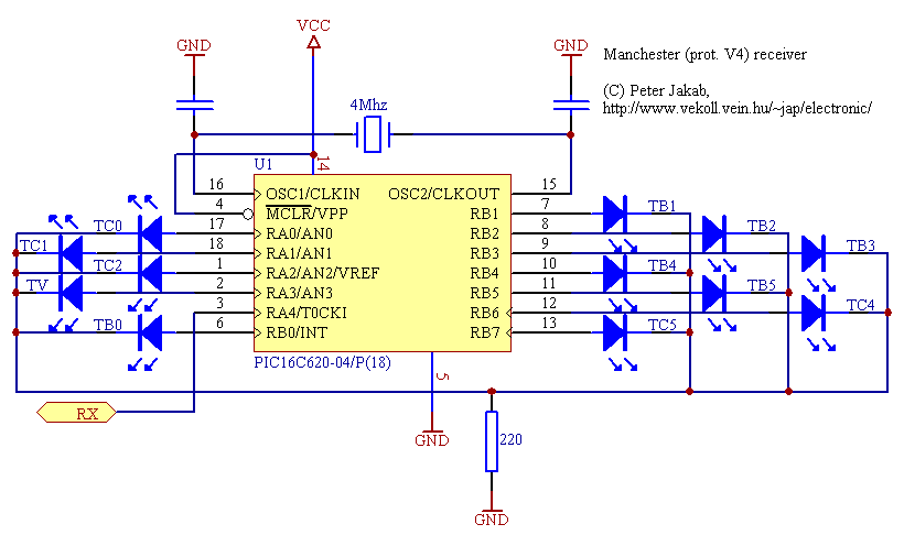
This version, when powered on, continously transmits the states of all inputs. The receiver will decode the messages and adapt the output states accordingly. The "TV" TTL output shows that signal reception is good. When the signal is absent for about a second, all outputs will go low and the TV out will be cleared. Files are mtx-014 and mrx-009. The transmitter has an ADJUST mode which outputs a periodic signal to calibrate the transmission channel. To enter this mode, press TC2 while turning the power on.
When powered on, in idle mode it emits a 800 Hz synchronization header signal. Otherwise, it will transmit a message like the V2 transmitter described below (tx-002). The hardware is also the same as with the V2 version (without the need for the diodes). Files are mtx-013 and mrx-007.
This one is designed to be a low power transmitter device with one button. It will transmit a message with the number of times the button is pressed. The unused inputs are used to drive a LED and turn on OSC before transmission (it can be used for ASK modulation). You'll have to face the challenge to code the receiver as it is not yet ready. Sorry, no schematic is available for this version. File is mtx-015.
This code is used to display the receiver code errors and buffers on an LCD display. At least 2x16 line is needed. The LCD library drives a special 3-wire serial interface designed by Myke Predko. File is mrx-008. LCD interface is in lcdlib.inc and lcdlib.asm, LCD hardware is described at Rentron. The E clock is separately connected.
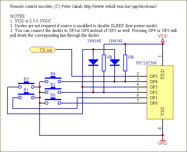
Encoder is a small, low power device which has 5 buttons and
by pressing one or more keys it transmits a message continously.
The transmitted message contains the state of all buttons and it
is sent in each message. On the receiver part, for all
transmitter buttons there exists a corresponding output pin which
will go high for the time the button is being pressed on the
encoder. Files are tx-003 and rx-003. I suggest that you consider
using the newer V4 devices or change a few lines to reduce speed
to 400/800 Hz (transmitter delay loop and receiver timer
prescaler).
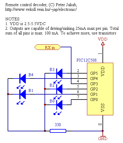 receiver input is GP3. To
reverse the receiver polarity (HIGH on transmitter OFF),
uncomment the define RX1010 in the source. Other pins are
outputs and capable to drive LED diodes or transistors
with relays.
receiver input is GP3. To
reverse the receiver polarity (HIGH on transmitter OFF),
uncomment the define RX1010 in the source. Other pins are
outputs and capable to drive LED diodes or transistors
with relays.By my own experiences I realized that you can't easily build these at home. I used the following devices: HX1000 transmitter (operates on 3.0-5.5VDC), RX1010 receiver (max. 3VDC) from RFM and small ready-made PCB panels: a receiver operating on 5VDC (RX3302) and a transmitter (9VDC). The PCB transmitter had a 300 usec wake-up which was too much at 1600 Hz with the V3 protocol. The RF modules are available from a lots of companies, check this link for a list.
If you don't have access to ready-made RF modules or want to build an infra version, please check my infrared circuits page. You can easily build these modules yourself.
I developed these programs on the PIC16f84 or PIC16f628 and when everything worked OK, I rewrote the programs for the OTP 12c508, 16c505, 16f620a devices. Use these files at your own risk (especially the compiled HEX binaries), please note that they are provided without any warranty.
| description | transmitter code | TX device | receiver code | RX device | default ID |
| 11-channel V4 transmitter and receiver | mtx-014 HEX |
16c505 | mrx-009 HEX |
16c620a | 9ae9 |
| 5-channel V4 transmitter and receiver | mtx-013 HEX |
12c508 | mrx-007 HEX |
12c508 | 9ae6 |
| one-button V4 transmitter | mtx-015 | 12c508 | c14e | ||
| monitoring V4 receiver | mrx-008 | 16f84 | 9ae9 | ||
| five-button V2 transmitter and receiver (old) | tx-003 HEX |
12c508 | rx-003 HEX |
12c508 | c1062864f14e |
| version | bit0 encoding | bit1 encoding | error codes |
| v2 | 1600 Hz (312 us H, 312 us L) |
800 Hz (625 us H, 625 us L) |
0 = OK 1 = error receiving byte 2 = timeout 3 = checksum error 4 = devid mismatch |
| v3 | 800 Hz (625 us H, 625 us L) |
400 Hz (1250 us H, 1250 us L) |
|
| v4 | 800 Hz (625 us H, 625 us L) |
800 Hz (625 us L, 625 us H) |
0 = OK 1 = illegal startbit 2 = signal too long 3 = signal too short 4 = no mid-frame transition/out of sync 7 = byte-ending bit1 missing 8 = byte-ending bit0 missing 9 = header too long 10 = header too short 12 = checksum error 13 = devid mismatch |
| posted by Rodney on 2001-10-20 05:09 |
| Dear Sir,
This is truly a great site. I spoke with an engineer who could not even come close to helping me build a T/X R/X set for a giant scale turbune jet project I'm working on. Is this design limited to only fice channels or scould I change the values and get more than five channels? Sincerely, Rodney |
| posted by Guillermo Acosta on 2001-10-19 17:37 |
| Hi everybuddy,
I'm programming the codes for PIC 12c508 (mtx-013.asm & mrx-007.asm) in PIC's 12c508a. I have a programmer PIC16PRO and along Verify Code Stage I obtain some error results in HEX code. I'm generating HEX files with Microchip Tools. I modify the original the codes .asm (mtx-013 & mrx-007) but follow apearing the error results ... somebody can helpme sending me advises on this trouble. Sorry on my bad english and thanks in advance. Guille guillermoacosta@hotmail.com |
| posted by Andy on 2001-10-18 00:19 |
| HI, nice page. i dont know if u can help but i need to build a IR receiver circuit using a pic16f84, having a bit of bother as i dont know how to do the amplification from the output of the IR diode into the pic.
Thanx in advance Andy |
| posted by jap on 2001-10-16 12:55 |
| Hi!
There's no layout due to the simplicity of the circuit and because it depends on the tx/rx module you can obtain. I don't recommend that you use this codec for security purposes, because the transmission can be recorded and played back. |
| posted by luz on 2001-10-16 07:33 |
| HI
I THIS IS AN GREAT PAGE, I LIKE, PLEASE, I NEED SCHEMATIC CIRCUIT OF RADIO CONTROL FUTABA THIS IS THE REFERENCE, FP-T5LK, ALSO THE SCHEMATIC CIRCUIT OF RECETOR BYE LUZ PLEASE IS MY AIRPLANE, PLEASE PLEASE |
| posted by José Gabriel Diaz on 2001-10-16 07:27 |
| hello
I like this homepage!! but i need an complete information of next integrated circuit, NE5044N, PLEASE, it`s very important for me, i need disposition of pin in this integrated and voltage - intensity, thanks José |
| posted by guillermo acosta on 2001-10-15 21:23 |
| Hi
Your site is very good. I'm been searching on engines for months for circuits stuff like this. I'm trying build a car alarm ... can you send me by email the circuit layout and components listing for 4/6/11 channel for radio version, please. Guille |
| posted by ADEM ÖZTÜRK on 2001-10-11 13:00 |
| please ı want wide documant and application circuit schema |
| posted by mike on 2001-10-02 22:14 |
| can the 11 channel units be modified to work with 2 PIC16F84s. How much software modification would be needed to make it work |
| posted by Drazen on 2001-09-29 07:40 |
| Can you tell me address and telephone of electronic shop in Budapest where I can buy HX1000 transmitter RX1010 receiver? On monday I am in Budapest. |
| posted by tom on 2001-09-26 14:00 |
| this site better than the outer shit sites |
| posted by Yury on 2001-09-18 13:53 |
| Hi!
I think it's the best site this thematic! I'll use this RC for my pirotehnics! Thank! From Russia with HI! |
| posted by Predrag on 2001-09-14 11:28 |
| Hi! Im so glad to find Your page on web because I looking something like this.
I will try 5 button V2 trx and tell me, I am not sure, if I push example button B0 on transmitter, can I give a signal on B0 (receiver), and if I press B1 on transmitter can I give a signal on B1 (receiver)..... And If You can help me, can I find HF transmitter an receiver shematic and source code something like Reynolds Electronics page 433 MHz TWS-434 transmitter and RWS-434 receiver. Thank You and "see ya"! |
| posted by mike on 2001-09-08 04:36 |
| Can the 11 channel remote work with two PIC 16f84s. What current does the transmitter use when not transmitting. Is this suitable for long term battery use or should the circuit be modified so that the PIC is only powered when a button is pressed?
good page mike |
| posted by aland shee on 2001-09-02 21:10 |
| reI need information-discription and operation from infra/radio remote control circuit with holtek encoder/decoder chips(ht600/ht615). Because I don't understand RF frequency and modulation in the circuit.
Oke, Thank's for your entention. |
| posted by erizza on 2001-08-22 04:15 |
| hi!can you give me a simple remote control circuit and also its schematic diagram ,for my project,digital karaoke box,a remote control that will control only the echo volume. |
| posted by terazi on 2001-08-08 12:38 |
| işine yara diye düşündüm |
| posted by DARWIN on 2001-08-08 12:38 |
| AS I READ ABOUT YOUR ARTICLE, IM HAPPY COZ I HAVE READ SOME OF THOSE ARTICLE W/C CAN HELP ME A LOT IN MY PROJECT. I MADE AN ENCODER, AS I USE MC145026 & MC145027 AS MY DECODER. I CAN SEND & RECIEVE 4BITS OF DATA & IT'S POSSIBLE FOR ME TO CONTROL 4 DEVICES. MY PROBLEM IS: HOW CAN I INTERFACE THE DECODER TO THE COMPUTER-ISA SLOT AS WILL AS THE RELAYS-THAT CONTROL DEVICES. I RESFECTPULLY ASK FOR YOUR ADVICE & A SORT OF SCHEMATIC DIAGRAM THAT CAN HELP ME INTERFACE MY PROJECT TO THE COMPUTER. PLS. |
| posted by Colin Mitchell on 2001-08-07 15:39 |
| Thanks for the very informative article.
Colin |
| posted by rabih chaar on 2001-08-06 07:35 |
| ineed aschematic and pcb and ahex file for v4 encoder &decoder |
| posted by kilroy on 2001-07-29 10:33 |
| Hi there. I am a bigginer in doing remote control projects. Can you show me a simple remote centrol projects for me to try it on? Say onlt one button remote control, for example for using as a remote control gate.Thx a lot.Bye |
| posted by Drazen on 2001-07-18 16:14 |
| Hello!
I have problem with remote control 5-channel V4 transmitter and receiver with IR. I put ordinal hex into PIC 16c508 and connect all like on your shematic diagram. I try to find what is the problem and I believe that the problem is on PIC 16C508 because I can`t measure on oscilloscope any output signal from pin 2 of transmitter. Oscillator works fine with timer 555. Is where any problem with hex? How works sleep mode on PIC and maybe is problem on that? Have you maybe hex and shematic for 16F84 (16C508 is on time programming pic and you can`t experimenting with him)? I try to put V2 protocol on PIC but the same problem exist. I see and other gays have the same problem (low output signal or nothing). Please help me with this. You have very good internet page. |
| posted by Sommart on 2001-07-14 05:48 |
| Dear sir,
Pls you send me the SCH for RF encoder and decoder and more information about this circuit. Thank you very much Sommart O. |
| posted by Majid on 2001-07-12 23:49 |
| Hi Dear
thanksful for this page |
| posted by john howard on 2001-07-01 21:22 |
| Peter, many thnks for the design, like many others, i cannot get the ht658/640 holtec chips now so this pic design is a real winner.I can by using the fsk now increase the range of my remote tx/rx's and if i can hear the signal on the scanner, i can get an output on the receiver. |
| posted by Chandrashekar on 2001-06-27 17:39 |
| Hi
this is a very good site i am been searching on google for weeks for stuff like this. i am a r/c airplane model enthusist although it was possible for me plan my own planes i always wanted to build the radio(tx/rx) myself so can u PLZ MAIL methe circuit layout and compnents listing for 4/6/11 channel radio it would be of great help. chandu |
| posted by Md.Habibullah Bahar on 2001-06-24 09:32 |
|
Thanks for the circuit diagram Bappy |
| posted by Omer bay on 2001-06-15 12:52 |
| for every think thanks..
best regards. |
| posted by jap on 2001-06-08 18:06 |
| The transmitter ID is not the same as the PIC ID. The latter is not accessible from the program. The transmitter ID is encoded in every transmission and verified by receivers to match. Search for "devid" in the source code to modify. |
| posted by rabih shaar on 2001-06-08 16:54 |
| hi
please ineed to know if ican use another id value like ffff , icant use 9ae6 for 5 chanel remote , when iput this id value { iread a message write error}when writing to pic 12c508 , when ffff itis ok what i can do . thank you |
| posted by john on 2001-06-03 16:45 |
| Hello
This is great page. I work easy wireless central locking system for car (PIC 12C508 or 12C509) with 1 input for DATA and 3 output for LOCK,UNLOCK and BLINKER I need software for just one channel encoder/decoder. Where in program you change the code for more rx/tx module??? I use Aurel rx/tx modul (www.aurel.it) My email: harpoon@email.si Regards John |
| posted by Sangit on 2001-05-11 20:01 |
| Excellent site for information about remote control.
Can I use 433.92 Mhz UHF transmitter and receiver IC modules like made of Micrel chips with your V4 PROTOCOL five channel remote control receiver and transmitter circuits ? Please send me a message . Thanks again. |
| posted by Francisco on 2001-05-01 07:19 |
| Please tell me if it posible decode a 1750Hz square singal from an audio channel
It's for a signaling sistem in a hamradio aplication, i'm think if you use it whit a rf module this work ok! Thank you Very much LW7DQB. |
| posted by electroij on 2001-04-18 22:13 |
| will be funtion
|
| posted by abaas on 2001-04-10 01:22 |
| can you please send me the part number of the IC in the 5 channel V2 schematic diagram.
Thanks once again. Abaas |
| posted by abaas on 2001-04-08 23:24 |
| hello,
i am still a beginner electronics hobbyist. can you please tell me what a .HEX. i am building a remote controlled car, can you please help me out. your site is the best i've been looking for schematics like the ones you have here for two months. thanks. abaas |
| posted by modest on 2001-04-03 22:04 |
| Helo,Iam very interested in your job.Iam an a R/C modeler.Iwould like to know it is possible to aplly in a FM transmiter your 11 channel V4 tranamiter and receiver.My tranamiter is a Futaba 4channels with chip encoder NE5044n in 35 mhz.
Tecnich date.duration of the pulse(ms) 0.9min 1.5neutral 2,1max 50mhz Thanks.From Spain |
| posted by cinar on 2001-04-01 10:42 |
| very good |
| posted by Will on 2001-03-20 07:56 |
| Excellent solution! However, could it possibly use the burned-in device ID as the program's device ID? Otherwise, I have to store a .HEX for every channel I wish to use.
Thanks, ---Will |
| posted by Pasas on 2001-03-12 13:36 |
| Nice work indeed, and thx for sharing it with us. I need your advice on a matter concerning this project. Can you please e-mail me if you want to that is. |
| posted by Jojo Ignacio on 2001-03-10 00:02 |
| I'm interested about this topic. In fact I'm trying to construct a wireless controlled lock. Can you help me develop a working system? |
| posted by riswan efendy on 2001-03-04 16:26 |
| for this time no comment.
thank you |
| posted by Rogga on 2001-02-28 21:50 |
| Hi there!
You´re doing a great job! I was trying to change some in the ASM-code, but the MPASM only complains there are some "CODE" and ".data" who don´t compiles...? Would you like to explain to me how I do to compile the ASM-code? I would be very greatful if you like that! Thanks in advantage! /Rogga |
| posted by raziff on 2001-02-20 06:52 |
| Hello,
Where can I purchase this HX1000 component. Please let me know. TQ |
| posted by Drazen on 2001-02-19 18:18 |
| Hello!
Where I can buy RF TX/RX modules in Europe and wich price is for this modules. Thank you. |
| posted by Mehdi Harati on 2001-02-19 06:37 |
| Dear Mr(s) :
Hello. Please send for me some informations of HX1000 and it's architecture. Thank you very much. Dr. M.Harati. |
| posted by Roger on 2001-02-11 14:21 |
| Hi! This is a very nice site, thank you for sharing it :)
But can you tell me why the 5-button rec only generates 20 mV, when it´s active? Thanx again. /Roger |
| posted by Graham Challis on 2001-01-23 12:35 |
| what a brilliant idea, thankyou but could you email me the compiled programme in either a .bin or .hex file so that i can programme the ic's as i do not have a compiler or understand how to do it
thanks once again Graham |
| posted by Samahudeen R on 2001-01-08 16:31 |
| I wand the Tx/Rx sections too, please. Thanks.
Samah |
| posted by JUDEAH B. DELA CRUZ on 2000-12-07 02:24 |
| Hi! Im Judeah of MIT. This is a great homepage!I badly need this circuit!Please send me the wiring diagram, the components, the PCB layout,PLEASE..PLEASE..PLEASE!!!THANKS!!!! |
| posted by Antal Kucsai on 2000-12-02 12:00 |
| I need this circuits. Please send me in email.
Thanx for help. |
| posted by Norbert on 2000-11-19 19:02 |
| I need a decoder for he RX3302 Receiver modul.
Thanks |
| posted by kenen bak on 2000-10-24 20:47 |
| Hi :)) I need TX'er(May be 1-2watt) and Rx'er with Rf encoder/decoder.If you help me I will be glad.Im a Electronics Technican and I need this circuits.Thanks alot.Have a nice works.
Kenan. |
| posted by ANDREJ on 2000-05-28 09:02 |
| Hi !
This a great page. I need the sch and pcb for rf encoder/decoder. Please send mee filles . Thanks Andrej !!! |
| posted by NO SPAM PLEASE on 2000-01-19 20:50 |
| Just wanted to say you are a life saver. I couldn't get ahold any Holtek Encoder/Decoder chips, but with this info, i don't need to. Plus, i can use the 8-pin SOIC chips which take hardly any space whatsoever. Thanks again.
dan |