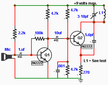
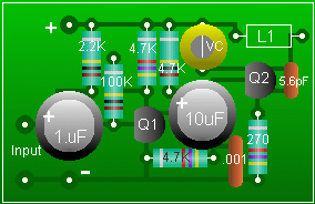
Mricophone FM Transmitter
 This little FM transmitter can be build unto a very small area
. It is very efficient and can be used for several
hundred yards or more. If it is to be used for a short range 100ft or less
a coil made of 8 turns of # 18 insulated wire on 1/4" dia. form can be used and no antenna is required
for short range . For long range up to 300 yards or more , the coil as described in the text for the TV/ Radio transmitter can be used .
This little FM transmitter can be build unto a very small area
. It is very efficient and can be used for several
hundred yards or more. If it is to be used for a short range 100ft or less
a coil made of 8 turns of # 18 insulated wire on 1/4" dia. form can be used and no antenna is required
for short range . For long range up to 300 yards or more , the coil as described in the text for the TV/ Radio transmitter can be used .
The microphone is from RadioShack Mini-condenser element Archer No 270-085.
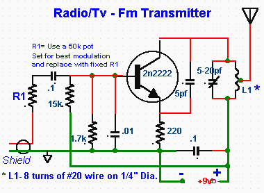
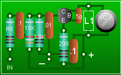
Radio/TV FM Transmitter
This transmitter was build and modified so that
I could watch my TV late at night without fear of disturbing the neighbors. As my TV does not have a headphone output I had to use something to extract the signal from the audio side. It is plugged into one channel of the stereo output with an RCA adaptor plug . With the TV sound level reduced to a minimum an excellent signal is obtained with full audio range which can be listened
to on small FM receiver tuned in at the lower band area or anywhere between 88 and 108MHz . The antenna is not required for short range transmission,ie..less than a hundred feet but if needed an antenna can be added by stripping the coil wire insulation at two turns from the ground end and a short lenght of 12 to 18 inches of stiff wire is soldered .
Setting-up and Tuning for Both Circuits .
Place the assembled circuit on a non conductive surface , it is important to keep hands and conductive material away from the coil. Connect a 9-volts battery in series with a multimeter or 0-10mA meter in series with the battery . Meter should read 5 to 10 mA. Slowly rotate the variable capacitor using a NON metallic screw driver such as fiber,plastic or even wood until the station being received by the FM radio at about 108MHz is blocked out or disappears.
It may be difficult to spot the signal as this adjustment is very touchy , note also that several spots in the adjustment may be found to produce a signal . Only two are valid , the rest being erroneous will be weak. Connect your input signal and adjust the 50K resistor for best signal reception then slowly readjust the FM receiver for strongest signal ot if you feel confident you try to readjust
the capacitor for the exact spot chosen on the FM receiver .
Trouble shooting- No signal .
While connected in series the meter does not register any current . This would indicate the the circuit is not oscillating , check all your connections also try reversing the coil connection , the circuit should oscillate and draw current without any input signal.
No signal is received at the FM set frequency on the FM band. The coil may not be formed to oscillate at the right frequency due to an extra or short turn, also make sure the coil end wire connections have been cleaned of its enamal covering and good solder joints where made. Try adjusting the coil by streching or compressing in very small steps until the signal is found somewhere on the FM band then adjust the capacitor as required.