

Video Signal Eavesdropping Threat Tutorial
Quite a few people have asked about video signals, deviations, video bandwidth and related countermeasures so it is a good idea to review the issue.
A "typical" TV video signal consists of two parts. The first is the Vestial Sideband AM signal with contains a sync signal, color signal, and the actual video information.
The signal is normally inverted in free space but is easily detected and viewed by using Raster Analysis or a Raid box. Also a "normal" TV can often be used, and simply manually tuned.
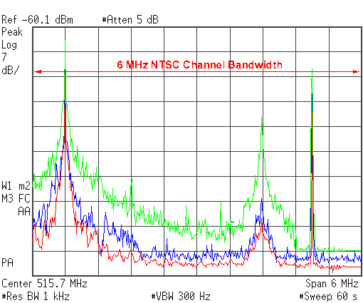
The allocated bandwidth is normally (in the US for a NTSC Broadcast signal) 6 MHz. Of this 6 MHz, 5.75 is for the COLOR video signal, and 250 kHz used for the audio signal (more on this later).
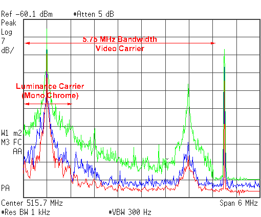
The "brightness", or monochrome signal is transmitted with a fairly narrow bandwidth. This is AM Modulated, but with half of the signal cut off to minimize the power and bandwidth required to carry the transmission (the lower half of the signal is trimmed off). This signal is easily viewed with an oscilloscope, and may be viewed on a monitor or RAID display by simply inverting the video.
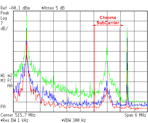
The Chroma (or color) signal is buried inside as a subcarrier riding the main signal (which consumes a lot of bandwidth). If the signal you are evaluating does not contain a Chroma subcarrier then it is a monochrome signal.

The audio signal is Wide FM modulated and is allocated 250 kHz which may or may not include the use of a SubCarrier buried inside (or riding on top of) the primary audio signal. One of the more popular Sub-Carriers (for eavesdropping) is the SAP and related channels. For more information on Sub-Carrier signals please see the tutorial on the subject.
If the 5.75 MHz video signal is added to the 250 kHz audio signal the entire 6 MHz channel width is used.

There are two timing pulses which are of great interest to a TSCM specialist. The first of these is the screen refresh sync pulse which is typically found just below 60 Hz. This signal is easily found by "tuning into" next to the video carrier signal (as above).
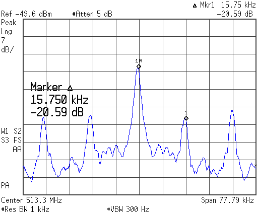
The second timing pulse that is also of great interest is the line retrace sync pulse which is typically found at 15.734 kHz. This is the signal that controls each line on the screen. This signal is also measured by "tuning into" the video signal.
This gives us a series of measurement points across each video signal which may be acquired by simply pre-programming them into a spectrum analyser. With a simple macro program (or DLP) the signal can be identified as either a monochrome or color signal, and all associated timing. Also, the presence of an audio carrier is easily confirmed (video eavesdropping devices often lack an audio signal, or have an un-modulated audio signal).
The following list reflects a few of the basic measurements that need to be made on any suspected broadcast video signal.
All of these measurements of broadcast video signals and a good understanding of TV allocations is critical as eavesdropping devices are often hidden inside the bandwidth of an active TV channel allocation. Hundreds of UHF wireless microphone products are also available (to the public) which operate inside the video signal bandwidth which effectively cloaks the hostile signal inside the hotter video signal. Such products are typically broadband, wide-FM (or spread spectrum), with special filters to notch out possible interference from the sync pulses.
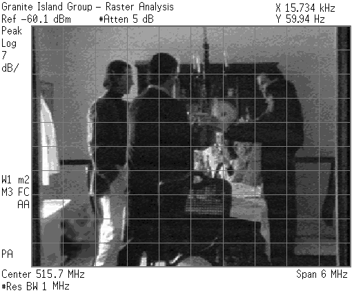
Once the timing has been determined (60 Hz/15.734 kHz) the actual image may be displayed on a RAID, Raster Analysis System, or Oscilloscope.
To display such a picture the raw image in applied to the Z-axis of the system (linear amplitude scale). Dual signal generators are then applied to the X and Y axis to simulate video timing. The amplifier on the Z-axis is then adjusted for brightness to cause the image to appear. A computer based raster analysis system works well as the timing is measured and supplied via software control (instead of using external circuits).
The 5.75 video bandwidth is what is ALLOCATED, but not always what is being used. For example the majority of the energy on a luminance signal (the BW monochrome brightness level) broadcast signal can usually be confined to under 1.8 MHz of bandwidth. A fairly clean video eavesdropping signal may be obtained by using less than 750 kHz of bandwidth.
PAL and SECAM format eavesdropping products are available, but tend not to be popular except for a handful of PAL products which are fairly easy to detect using the same methods applied to NTSC format signals. (The PAL and SECAM bandwidths are wider than NTSC).
Another way of looking at it is that the eavesdropper can easily "hide" his video transmission inside a bandwidth of less then 1 MHz.
If the eavesdropper is using a low grade CCD element, and doesn't transmit sync pulses the bandwidth can be further reduced to well under 600 kHz of RF bandwidth.
All this assumes the eavesdropper is transmitting a standard AM modulated NTSC broadcast signal on an allocated channel (most are not).
Instead the eavesdroppers are clustered around RF channels 2 and 3 in the VHF bands, and an assortment of high channels (which will be covered in a moment).
Eavesdroppers also heavily use the amateur bands around 434 MHz (usually 433.92 MHz), and 1.2-1.5 GHz with many of the products using wide-band AM or FM modulation. Remember that the signal bandwidth is between 1 MHz and 8 MHz, so the FM deviation can be between +/- 1.5 and 12.5 MHz or higher.
The 900 MHz and 2.4 GHz ISM bands are also popular, and widely used with heavy usage of the Wavecom and Trango type of products. Complete 900 MHz eavesdropping products are available for under $150 in many department stores.
The 5.7-6.2 GHz ISM band is starting to be widely used by eavesdroppers, but it will be several years before the band is used heavily.
Of course there are the 1.7-1.95 GHz products that "fall off the truck" and end up being used by PI's, along with the 1.9 - 2.5, 4.4 - 5.0, 6.4 - 6.5, 8.2 - 8.6, and other popular surveillance bands up to about 18 GHz. This equipment is typically only available to LE channels but has a bad habit of showing up in places it shouldn't when someone takes it home. It's not uncommon to find such equipment at ham shows, pawn shops, and even spy shops (but the spy shops get premium dollars).
The majority of the higher end products uses AM or FM modulation with a bandwidth of 5 to 25 MHz, and often contain multiple audio or command/status subcarriers.
Watch out for the Digital Video (DTV) eavesdropping devices which convert the video signal into a DS-3 45 Megabit compressed data stream (watch for the QAM or BPSK signal, and the ATSC pilot).
As a rule expect to see hostile video signals between 3 kHz and 18 GHz for Threat levels 1, 2, and 3. Watch the higher frequencies up to about 40 MHz for the "spot beam" products operating around 30-35 GHz which are typically restricted to Threat Levels 4 and 5.
Watch those FM deviations and subcarriers as both can seriously ruin your day if the video is being transmitted as a subcarrier with suppressed sync.
Expect FM deviations between +/- 300 kHz and +/- 20 MHz, and considers purchasing an AVCOM VDM-2 and REI VBA to play with for a better understanding of the FM video threat.
Conducted Video Threat
Virtually any conductive or quasi-conductive element may be used by the eavesdropper to carry video out of an area. If an eavesdropping has sufficient time at the target area a system of high quality coaxial cable may be concealed.
On the other hand if time is limited the eavesdropper may instead use previously installed telephone wiring, power lines, alarm circuits, HVAC duct work, or even the tack strips under the carpet. This is why it is critical to locate and evaluate EVERY conductor in a area during a TSCM survey.
Watch out for base-band conducted video over the AC or telephone wiring, and carrier current video signals running wide-band FM modulation up to around 3-8 MHz.
Evaluate every conductor combination both in the time (Oscilloscope) and frequency domain (Spectrum Analyzer) and don't just look for complex video waveforms but also for signal artifacts such as the timing signals.
Also keep an eye on all other twisted pair wiring, telephone cable, LAN/WAN cabling, and any other combination of conductors, as it's easy to pass a decent video signal with less than 1 MHz of bandwidth.
A tuned loop with resonance on the 15.734 kHz sync pulse may also be used to locate conducted video signals. The loop is coupled via a simple balun circuit and then passed to a preamplifier circuit which provides 25-30 dB of gain. When properly used a conducted video signal may be detected from several feet away, but less then a foot is typical. If the eavesdropper was sloppy when installing the device then detection distances of over 10-15 feet is possible (but don't count on it).
...of course your mileage may vary...Click HERE to obtain more TSCM Tutorials
![]()
Any comments or questions regarding this specific page?
Please feel free to sign our Guest Book
![]()
|
To be contacted for a confidential consultation please E-mail: jmatk@tscm.com
or send a letter via US Mail to:
or call:
URL: http://www.tscm.com/ |