INTRODUCTION
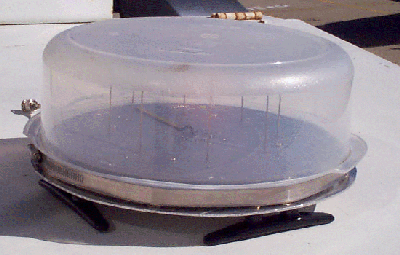
The “mini - array” described here is fabricated entirely on a circular PC board, ( 10 inch diameter ) and includes the antenna ground plane and antenna elements, as well as the RF switching circuits. It is small enough to be enclosed in a plastic radome, and offers increased UHF performance ( field - tested at 150, 450 and 800 Mhz ) as well as increased convenience for installation, storage and / or shipping.

( ...Yeah, it's Tupperware... )
Conversely, the reduced antenna size will cause RF sensitivity to suffer, and will reduce the amount of Doppler shift output, due to the reduced diameter of the antenna array. This will be particularly true at lower frequencies, ( below 100 MHz ) where the mismatch between antenna size and signal wavelength becomes more severe.
These drawbacks were judged to be less important than the increased convenience and utility of such an antenna, in most DF situations... the resulting array is small enough to be removed and stored in the trunk of a vehicle, making it available on short notice, when required.
A prototype has been constructed and ( briefly ) field tested, with good results. Photos are provided here, as well as the schematic, PCB artwork and a parts list.
GENERAL PROFILE
This "mini-array" antenna has several virtues, compared to the original antenna design. It employs SMT ( surface mount technology ) components in all the critical RF circuits to improve UHF performance, and uses 50 ohm stripline antenna circuits to connect each antenna to the PIN diodes. It also has PCB "footprints" for SMA type RF connectors at each antenna, as well as the the RF output point, and provides a 50 ohm "dummy load" for each de-selected antenna, to stabilize the load impedance observed by the antennas.
Aside from the ( new ) 50 ohm “dummy load” resistors, the schematic is essentially unchanged from that of the original antenna board, although component values are different. The biggest change involves close attention to “RF hygiene”, which severely limited the maximum useful frequency of the original antenna PC board. Great care was taken to preserve the geometric symmetry of the RF switching circuits, since this was the biggest flaw in the original antenna board.
As a consequence of this, a few of the components must be “hand wired” on the board. Even though PC board tracks and pads could have easily been provided for these components and circuits, installing these tracks would have divided and separated the ground plane areas around the ( critical ) RF switching circuits, with unpredictable results, especially at higher frequencies... it was judged better to preserve the circuit symmetry, and suffer the appearance of a “hand carved” circuit, rather than risk a sacrifice of performance for purely cosmetic reasons.
PROTOTYPE FIELD TESTS
This antenna has been constructed and ( briefly ) field - tested at 150 MHz, 450 MHz, and 800 MHz, with good results. Critical / objective RF bench tests have not been performed, ( loss, switch isolation, VSWR, broadband performance, etc. ) since I do not presently have access to the necessary test equipment.
The initial field test used the local NOAA weather station, operating at 162.400 MHz, which produced a strong RF signal, at a range of about 7 miles. The transmitter is located on a nearby mountaintop, at an elevation of about 3500 feet, and has a clear field of view in all directions for many miles. This transmitter was chosen for the tests because it provided almost ideal test conditions...I didn’t want to confuse antenna design problems with other “real world” problems, caused ( for example ) by a low power signal in a high reflection environment. By all the observable criterion, the antenna performed as well as anyone could expect, and demonstrated no detectable problems. RF sensitivity is completely unknown, because ( of course ) with an FM reciever, all signals above a few microvolts produce equal audio level and quality.
A second ( brief ) set of field tests was later performed at 450 Mhz and at 800 MHz, with similar ( goods ) results... in this case, the station locations were unknown, and the stations themselves were unidentified... I simply "scanned" the bands to find stations that were on the air continuously, to facilitate the tests... This being done, the vehicle was driven to a clear area and slowly rotated to all headings while observing the relative and true signal bearings.
The resulting signal bearings behaved as expected, and "grouped together" into a sector of about 20 - 30 degrees of width... I suspect perhaps half of this width ( maybe more ) was due to errors in the compass, which was not installed in the center of the vehicle roof, and which had no correction mechanisms, either in hardware or software.
During the second field test, antenna behavior on 162.400 MHz was also checked again, and still found to be accurate.
The prototype antenna did not employ SMA connectors, simply because I didn’t want to spend $30 for them... the antenna elements ( 4 inch braising rods, 3/32 inch diameter ) were soldered directly to the PC board. The output RF coaxial cable ( RG-174/U ) was also soldered directly to the PC board, and secured to the surface of the ground plane with a small brass tube, visible in the photos. In hindsight, I should have probably installed this on the underside of the PC board, ( away from the antennas ) but for reasons I can’t recall, this did not happen... in any event, it did not appear to adversely affect the antenna performance.