| Gollum´s Crystal
Receiver World Back to previous page |
Gollums
Kristall-Empfaenger Welt Zurueck zur Vorseite |
Copyright (C) 2000, Berlin, Germany. Rainer Steinfuehr
FM crystal receiver with slope demodulation. Construction project.I have this "FM receiver" in use. It works only near transmitter sites. Reception range is approx. 4-7 miles using a 3 Ele. Yagi antenna. You will need an impedance and symmetry transformer (balun 240/75 ohms). The antenna input impedance of the receiver is about 52 to 75 ohms. Tune the variable capacitor for best sound quality. Slope demodulation needs critical adjustment. Try tuning a little off frequency to receive undistorted audio. While assembling the receiver try to keep all wire connections short. Particularly the coils need care in windingl. The VHF choke can be made by winding 3 to 5 turns of wire on a suitable VHF ferrite core. When you still have old 240-ohms flat twinlead and want to use it:: Change coil L1 to 2 1/4 turns. Remove ground connection of L1 (point c) and mount a suitable antenna socket for flat band cable. Advantage: Yagi and dipole antennas have 240 ohms impedance and you don't need any balun transformer. This means less losses, and greater reception range. The 50 pF tuning capacitor, the diode and the crystal ear phone you can order here. |
UKW-Detektor mit Flanken-Gleichrichtung. Bauprojekt.Detektor fuer UKW-FM-Empfang. Arbeitet nur in der Naehe eines Senders. Empfangs-Reichweite ca 6-10 Km bei Nutzung einer 3 Ele. Yagi-Antenne. Wenn Sie eine Yagi-Antenne benutzen, muss diese Antenne einen Impedanz- und Symmetrier-Trafo (Balun 240 / 75 Ohm) haben. Der Antennen-Eingang des Empfaengers hat eine Impedanz von 52-75 OHM. Stimmen Sie auf beste Klangqualitaet ab. Die Flanken-Demodulation ist etwas kritisch einzustellen. Eventuell muss etwas neben die Frequenz abgestimmt werden, um die Modulation unverzerrt zu empfangen. Bauen Sie den Empfaenger so zusammen, dass alle Zuleitungen kurz sind. Die Spule ist besonders sorgfaeltig zu bauen. Die UKW Drossel (VHF choke) kann mit 3-5 Windungen auf ein kleines Stueck UKW-Ferrit gewickelt werden. Wenn Sie noch altes 240 Ohm Flachband-Antennen-Kabel haben: Aendern Sie die Spule L1 in 2 1/4 Windungen. Entfernen Sie die Verbindung von L1 zur Masse (Punkt c). Nutzen Sie eine symmetrische Antennen-Buchse. Vorteil: Yagi- und Dipolantennen haben 240 Ohm Impedanz. Sie brauchen keinen Balun-Trafo, um auf 75 Ohm zu transformieren. Weniger Verluste, groessere Reichweite. Den 50 pF-Drehkondensator, die Diode und den Kristall-Hoerer koennen Sie hier bestellen. |
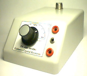 |
The experimental model sports connectors for both crystal ear phone and old-time 2000-ohms impedance models. The latter are less desirable since they put a heavier load on the resonance circuit. This means the resonance curve will not be as steep. I used a SO239 as an antenna socket (PL). A BNC socket is also suitable. Das Versuchsmodell hat neben dem Anschluss fuer einen Kristall-Hoerer noch Kontakte fuer alte 2000 Ohm-Hoerer. Diese 2000 Ohm-Hoerer sind weniger gut geeignet, da sie den Schwingkreis staerker belasten. Dadurch stimmt die Durchlasskurve nicht mehr gut zur Flanken-Demodulation. Als Antennenbuchse benutze ich eine SO239 (PL) Buchse. Sie koennen aber auch eine BNC-Buchse verwenden. |
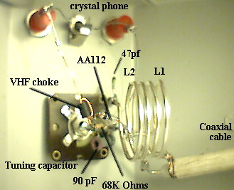 |
The VHF choke is only needed when the ear phone jack is connected to the diode with long wire. Solder the 47 PF capacitor and the 68 kohms resistor as short as possible to common ground (point c). Die UKW-Drossel brauchen Sie nur, wenn die Leitung zur Ohrhoerer-Buchse weit von der Diode entfernt ist. Der 47pF Kondensator, der 68k Ohm-Widerstand muessen kurz mit der "Masse" der Schaltung (Punkt c) verbunden werden. |
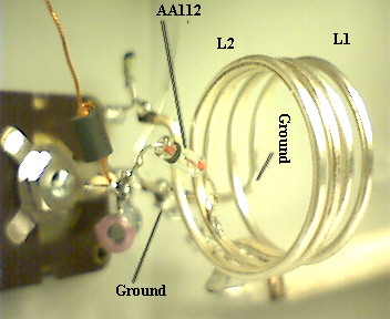 |
The two coils L1 and L2 are installed side by side. Connect both "ground" ends directly with the ground pin (rotor) of the tuning capacitor (point c). Keep the coil windings apart from another. Die beiden Spulen L1 und L2 liegen dicht nebeneinander. Beide "Masse"-Seiten direkt mit dem "Masse"-Punkt (Rotor) des Drehkondensators (Punkt c) verbinden. Die einzelnen Windungen der Spulen duerfen sich nicht beruehren! |
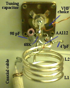 |
The diode AA112 is soldered directly to the 1-turn tap of coil L2 ( point a). Protect the diode from exessive heat when soldering! Die Diode AA112 wird direkt an die Anzapfung (Punkt a ) geloetet. Die Diode darf beim Loeten nicht zu heiss werden! |
 |
Construction plan for a simple
dipole antenna. Using 240-ohms twinlead a good FM-dipole may be made. Connect the twinlead free of obstructions. Cable lenght may be as long as 10 meters (30 feet). When twinlead is not available: a makeshift flat band cable may be manufactured by pasting two isulated copper wires to cardboard strips keeping them seperated at a constant 8 millimeters. Wire thickness 1.2 mm (AGW # 16 or 17). Bauplan fuer einen einfachen Dipol. Mit einer 240 Ohm-Antennenleitung kann ein guter UKW-Dipol gebaut werden. Befestigen Sie den horizontalen Dipol moeglichst frei. Die Laenge der Zuleitung kann bis zu 10 Meter betragen. Wenn Sie kein Flachbandkabel haben, koennen Sie es auch selber herstellen: Kleben Sie zwei isolierte Kupfer-Draehte im Abstand von 8mm auf Pappstreifen. Drahtdurchmesser 1,2 mm. |
 |
Construction plan
for a 3 element Yagi antenna for FM band. Use copper tubing with an external diameter of about 1 to 1.5 centimeters (0.4-0.6 inch). The mid-point of the upper tubing of the folded dipole (c) must be soldered to the antenna boom. Also the reflector (a) and the director (b). Lenghts are: a= 174cm (68.5 inches), b = 128 cm (50 3/8 inches), d= 6cm (2 3/8 inches). Distances reflector (a) to folded dipole (c) 85.5 cm (33 21/32 inches). Distance director (b) to folded dipole (c) 51 cm (20 inches). Dipole feedpoint E,E either 240-ohms twin-lead or a balun. Obey safety rules when installing the antenna outside! Bauplan fuer eine 3 Element Yagi-Antenne Das Material fuer die Yagi sollte aus Kupferrohr sein. Durchmesser der Rohre 1 - 1,5 cm. Die obere Mitte des Dipols (C) wird mit dem Mittel-Traeger-Rohr verloetet. Der Reflektor (A) und der Direktor (B) ebenfalls. Laengen: A 174 cm, C 143 cm, B 128 cm, D 6 cm, Reflektor (A) - Dipol (C) 85,5 cm, Direktor (B) - Dipol (C) 51 cm, Dipol-Antennen-Anschluss Unterbrechung (E,E) 5 cm. An Punkt E wird entweder das 240 Ohm- Antennen- Kabel oder der Baluntrafo angeschlossen. Beachten Sie bei Aussenmontage die gesetzlichen Sicherheitsvorschriften! |
 |
Construction plan for a balun
transformer. When using ordinary coax cable to connect the antenna you have to transform the 240-ohms antenna impedance to the 50-75-ohms of the coax cable. For the balun use RG58 coax cable, length is 1 meter (39 inches). Solder the connections as in the drawing. Connect to folded dipole at points a and b. Antenna cable may be any coax cable of 52 to 75 ohms impedance. Bauplan fuer einen Balun-Trafo Wenn Sie ein heute uebliches Koaxial-Kabel an die Antenne anschliessen wollen, muss der 240 Ohm-Ausgang der Antenne auf die 52-75 Ohm des Antennen-Kabels angepasst werden. Besorgen Sie sich bitte ein RG58 Ohm Koaxial- Antennen-Kabel (Laenge 1 Meter). Loeten Sie dieses Kabel wie in der Zeichnung gezeigt zusammen. Sie koennen die sich bildende Schleife in zwei oder drei Windungen aufrollen, um weniger Platz einzunehmen. An A und B wird direkt der Dipol angeschlossen. Fuer das Antennen-Kabel koennen Sie ein uebliches 52-75 Ohm Kabel verwenden. |
Thanks to my friend Peter Sepponat for translation