THE PROJECT CRYSTAL RADIO
(updated 4 Feb 01)
The Project Crystal Radio involvesthe construction,
testing and operation of a series of
crystal radios, starting witha very
basic set and ending up with a medium performance dx set, completewith antenna
tuner. While it uses a smallish gage enameledwire (#24) and
the cores of toilet paper or towel rolls, it works ratherwell throughout, and
the coils are easy to wind. In addition to thesuggested parts used here,
you will also need a decent antenna and ground,preferably with alligator clips
attached so you can fix them to your setswherever needed. Throughout, I
selected parts based on availabilityand cost. Using standard catalog
parts from Mouser and Radio shack,you should be able to complete the project
for about $25, less if you shoparound, more if you decide to go with more
expensive components. Here are the electronic parts I used:
Rf tuner capacitors- 2 - ElectronixExpress p/n 14VCRF10-280-P @ $1.35 ea
Screws
for tuner caps - 2 - Mouser p/n 48ss003 @ $1.20/100
Capacitors withknobs and
mounting screws are also available at kitsrus
Capacitor withknob also
available at Ocean StateElectronics
Ceramic earphone- 1 -
Mouser p/n 25CR060 @ 1.85
Magnet wire #24- 1 lb -
Mouser p/n 501MW24H-1LB @ 10.42 (this gets you about 750 feet,you will only
need about 200)
1N34A diode -Radio Shack
- 1 - @ 1.19 for 10
47 kohm resistor- Radio
Shack - @ .49 for 5 - either 1/4 or 1/2 watt will do
Parts from Mousercan be gotten from their web site; search using the
part numbers I havegiven here.
Other stuff I used:
Fahnestock
clips - 3 - Mouser p/n 524-11-4034C @ .21 ea.
Alligator
clips - 8 - Radio Shack - p/n 270-356 or something similar -about 2.29.
Double
sided sticky tape - couple of inches will do - rtv or hot glue will do as
well, but is more permanent. Use for mounting the capacitors
Antenna,
ground and hookup wire - a 90 foot roll of #22 strandedhookup wire from
Radio Shack at 3.99 will do.
1
foot of 1 x 4 or 1 x 6 pine
1
foot of 1/4 inch lath (see photo)
1/2
inch wood screw - 3 - to hold fahnestock clips to base.
1
inch wood screw - 2 - to hold uprights onto base
Two
plastic bottle caps for tuning knobs
Two
small washers from hardware store (Ace), about 1/3 inch diameter, tofit under
screws for capacitors and hold "knobs" in place.
1/8
to 1/4 inch dowel, 13 inches
Toilet
paper cores - 3. Paper towel rolls cores also are ok. Diameter
should be about 1 3/4 inch.
The two larger coils we will use areabout 400 uH
each, and the capacitors will go from about 20 to 220 pF -enough to cover the
AM broadcast band. If you want to play aroundwith different size coils,
wire, capacitors, etc., go ahead if you knowhow to adjust. If not, I
recommend you keep to the directions.
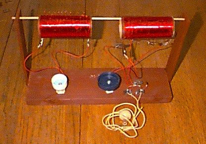
Construction: First, let's lookat a picture
of the completed base of the set and the two main coils youwill wind.

The coil on the left is coil#1, and has 17
taps. The other coil is coil #3. The verticalstrips are the lath
material, screwed to the 1 foot long base. Holesdrilled in the ends of
the lath hold the dowel rod; it can be removed tochange coils. The bottle
caps are the knobs of the two polyfilm rftuner capacitors, which are stuck to
the base with sticky tape. On the right of the base are screwed 3
fahnestock clips. The detectoris connected between the rear clip and the
right front clip. Leadswith alligator clips are connected to the right
rear and front left fahnestockclip, and leads and alligator clips are also
connected to each capacitor. The two front fahnestock clips are for
phones. Antenna and groundleads should be connected to the coils using
alligator clips. Youcan use the picture to figure out how to put the base
and parts together. I will show a "ready to listen" picture
later.
Before you wind coils, I recommendyou put your base
together as shown above. You can be much less "elegant"than
this, such as putting the whole mess on a shoe box top. I usedthe wooden
base for stability, however, and the elevated coils to giveme better access to
the coil connections and to get the coils a bit awayfrom surrounding metal,
which can adversely affect coil Q.
Preparation ofthe capacitors:
The
capacitors I used have three connections. The center one is thebase, and
the outside ones are for the rotors of the two sections. You need to
connect the two outside ones, and connect them to one lead,about 8 inches long,
and connect the center connection to another lead. If you look on the back
of the capacitor, you will notice two small trimmercapacitors with a
screwdriver adjustment. Adjust both these to minimumcapacitance ( you
will see a full circle instead of a half-moon shape);this will give you full BC
band coverage when used with the coils you willwind next. Cut holes in
the center of the two plastic bottle caps,and shape them with a knife to fit
snugly over the tuning shaft of thecapacitors, and then hold them in place with
a small washer and screw. Use the double sided sticky tape to mount the
capacitors on the base, andfasten alligator clips to the ends of the
leads. To avoid workingthe delicate capacitor leads, I used an ordinary
stapler to staple theleads to the base close to the caps.
Construction
of coil #1: This takes about 72 feet of #24 wire. Using a pin, punch
two holes about 1/4 inch apart close to and parallelto one end of your coil
form. Thread about an inch of wire into onehole and out the other to
anchor your coil. Now wind about 152 turnsof wire in a single, closely
wound layer along the coil; at every10 turns (yes 10), make a small loop
that sticks above the coil, each loopbeing about 1/4 inch in diameter - you
will get the hang of this quickly. To avoid crowding these loops, which
you will use as taps, you might staggerthem so every other tap is offset on the
coil by about 1 inch; you willend up with two rows of taps. After the
last turn, make a final tapand, use the pin to make two more small holes as you
did in the beginning,and thread about an inch of wire in and out to
anchor the other endof the coil. You can use either cement or white glue
to hold yourfinished turns onto the coil form. Tape is ok too; just don't
coverthe taps. Now comes the really tedious part; getting the enamel
offthe taps. I usually take a small flame, as from a lighter or
candle,and burn the enamel off the tap, then lightly sandpaper them
clean. If you like, do as I do and tin the taps with solder. This
coil willeventually be used for your antenna tuner, hence all the taps.
Idon't draw well, so here is a link to what a tap should look like:

After you
have completed coil #1, assembled the base, and put up your antennaand ground, you
are ready to build the first couple or 3 radios in theproject.
Construction
of coil #2: For this coil I recommend 30 turns on thesame diameter core,
with taps for connections only at either end. Takes about 14 feet of wire.
Constructionof coil
#3: This coil can be identical to coil #1, but, since I didn'tthink I
needed all the taps, I just put them at 0, 15, 25 50, 75, and 152.
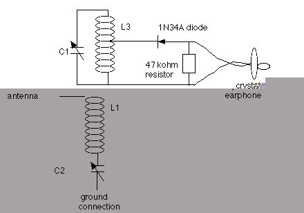
Let's
make aradio: The first radio is a simple conductively coupled
set,using only the antenna/ground, coil #1 and the detector and phones
(earplug). It is commonly built as the "oatmeal box"
set. Here is theschematic for it:
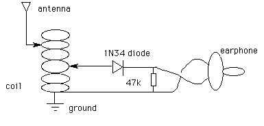
Operatingand things to try:
The
set is "tuned" by using the inductance of the coil and the
capacitancebetween the coil turns by attaching the antenna to various
taps. Put the detector tap on different taps for the best signal.
You willnotice that this set tunes rather broadly, but may receive some
shortwaveas well as broadcast band stations. You can try
disconnectingthe ground connection from the coil and connecting it and the
detectortap to each other, putting the detector and earphone in series with
thecoil. Try reversing the diode, and try it without the 47kohm resistor.
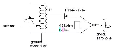
Radios numbertwo and
three. These use the same components as above, but with theaddition of
one of the variable capacitors. Leads from the capacitorgo to both ends
of the coil for radio number two, creating a parallel tankcircuit. For
starters, tap the detector about midway on the coil,and connect the antenna to
a tap close to the ground end. Adjustboth taps for best reception.
At this point, you should be wondering"what should I be able to hear?"
An educated guess can be obtainedby using the scan function on your car
radio. You should expect tohear with your xtal set the stations that the
radio stops on every timeit tunes through the AM band. Strong stations
may dominate partsof the band on your xtal set, but we'll work on that
later. For some reason, most renditions of this set put the detector
and the antennaright at the top of L1/C1; this never works very
well for me,but putting the detector between 30 and 50 percent up the coil and
theantenna tap somewhere near the bottom seems about right. For a
simpleradio, just connect the antenna to the top of the tank circuit, and
forgetthe ground; this is the basic kid radio, and you can go around
touchingthe antenna connection to various metal objects around the house to
seewhat you can get. I get a couple of locals this way. Here is a
schematicof this radio.
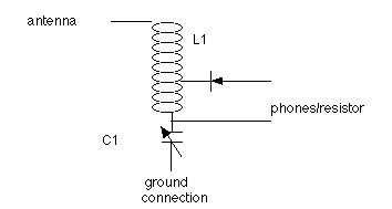
An alternativeto this
arrangement is to put the coil and capacitor in series insteadof in parallel,
thereby making radio number three. Your choice asto which is closest to
the antenna. Give them both a try. Tapthe detector and phones at
several points and see which is best. By this time you should be getting
a feel for the best taps for selectivityand sensitivity (read loudness) for
your detector and phone taps. Feel free to reverse them, to reverse the
diode, and to try different diodes,or add diodes in series or parallel with
each other to see the results. Oh yeah, by tapping the antenna way
down the coil, you may pick up someshortwave stations, particularly at
night. The series xtal set isshown here:
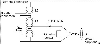
Radio number four. By now
you may be wanting a little more selectivity, particularly if youhave two
strong locals close together on the dial. Here is one wayto do it.
First, return your radio to the parallel tank circuit ofradio number 2. Put
coil #2 on the rod near the ground end of coil #1 (theend connected to the
earphone lead). Now connect the antenna andground to coil #2. By
separating coils 1 and 2 you vary the couplingbetween the antenna system and
the set, and can pick up some selectivity. This should allow you to keep
the detector on the best all-round tap, andnot lose sensitivity by having to go
to a lower tap to gain selectivity. Feel free to experiment. Here is
the arrangement for this set:
Radio number five. This one
uses coil #3, which has been waiting patiently in the wings; ifnot, then wind
it now. For this set, you will take coil #2 off thedowel, and put on coil
#3 in its place. Now connect the detector/phoneleads to coil #3.
This gives you a separate antenna tuner using coil#1, inductively coupled to
the set's tank circuit which now uses coil #3. Adjust for the best
taps. Use coil #1 in the series or parallel tankcircuit configuration of
radios two and three, or just use as an antennaloading coil, without the
capacitor. A schematic of this arrangementwith coil #1 as a series tuned
antenna tuner is here: (note: as built,the antenna tuner configured as a
series tuner shown below didn't tunebelow about 650 kHz; to go lower I had to
shift to a parallel arrangement,and connect the antenna to a tap on the coil)
From here on out,we will use the
configuration of radio number five, and try out differentways to tune the
antenna. With the set you now have, you can tryout any of the
configurations on my antenna page, linked below, with thesingle exception of
the one with two capacitors on the antenna tuning coil. For that, you will
need to get either a third capacitor or a ganged dualcapacitor of sufficient
capacity - I recommend the latter. From hereon out you're on your own,
but you now have a set that will pick up somegood dx, and give you some
experience in preparing to build your own ultimaterig. Have fun.
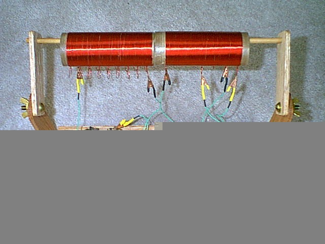
Oh yeah, here'sa picture of the
set in a "ready to listen configuration" - just add antennaand
ground.
One final afternote: This sethas a number of
compromises which were made on the basis of parts availabilityand cost.
In fact I scaled it up to incorporate some more advanced( and costly) features
for my own use. The basic design is soundhowever, and it is my new
"gold standard". It also has theflexibility to allow me to try
out new ideas with little difficulty. The only claim I make is that
you cannot buy a better set, eitherready-made or in a kit. During the
latest (2000) dx contest, I usedthis set as shown, but with the earphone under
a pair of sound isolationmuffs, and with one of my in-line wave traps.
Got 52 stations justlistening in my spare time, which wasn't bad at
all. The rigI sent in my logs for was a scaled up version of this with
some detectorand headphone mods, and logged 98.
For a nicer looking version of thisset, see what
Dennis Foster, KK5PY sent me:
HOME LINKS
CONSTRUCTIONTIPS COMMENTS
ANTENNAS
TESTING
REVIEW