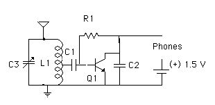
Okay, here is another little radio for you to play with. Doesn't seem like much, but it has some very interesting features, needing only a tiny handful of readily available parts, and having a lot of flexibility in its operation. It is a basic audion design, where the transistor acts as both detector and amplifier. Yes, it is very similar to the amplifier I use in my crystal convertible and super convertible receivers, but with two basic differences: The value of R1 and the additon of C2. Here is the basic schematic of the set, with lots of notes to follow:
First, the parts list:
Q1 can be any of a variety of NPN or PNP
(reverse the battery) transistors. I tried successfully a 2N2222,
a 2N3906 clone from a Radio Shack bulk pack, a 2SC945, and the 2SA
and 2SC transistors from my RS project kit. The schematic I
referred to used a BC458.
The tank circuit L1/C3 is your choice of
a resonant circuit. L1 is tapped 20% from the ground. My "student
model" used a 220 pF polyfilm variable capacitor, and a 1 3/4 " ferrite
core from the Goldmine, with 90 turns of #32 enameled wire close wound
on a 5/16" paper form (made by gluing a piece of typing paper around a
5/15" drill bit with some school white glue), with a tap at the 18th turn.
C1 can be from 0.1 uF on up; I used as high
as a 10 uF electrolytic (the latter called for in the original design).
Less than the minimum value shown affected performance adversely.
If you use an electrolytic, observe polarity (positive to the base if NPN,
etc)
C2 is a 0.1 uF capacitor - less is worse
- I didn't bother with larger.
R1 is 100k ohms. I tried a variety
of values using a 1 Megohm pot for the different transistors, and the best
value kept showing up right around 100 k, so I don't recommend messing
with it, unless you want to. I suspect the optimum value might be
around 92 k, but you'll never notice, and who has that value laying about
anyway?
For the battery, more is not better. In fact,
I was using a very used 1.5 V AA with a no load voltage of about 1.2 V
- worked fine. This circuit draws about 1 to 1.5 mA, depending
on whether you are using a new or used battery. You might be able
to sneak it up a little, but go back and check the value of R1 if you do.
What R1 does is set the proper bias voltage on the BE junction; you can
experiment with it, just listening by ear, to get it right.
Layout and wiring are not critical, and you can go from a neat PC arrangement to "dead bug squashed flat" ( my personal favorite).
Now for the fun part:
This little circuit will drive just about anything for phones, with decent results. I was even able to use cheap, insensitive dynamic stereo phones from the Dollar Store with it. It worked best with the phones connected in series to give me 64 ohms dc resistance. I used a stereo jack from RS (2/$1.99), and connected the two outside phone connectors only in the circuit, leaving the ground connection alone to do this. The same jack will also accommodate a mono plug when wired this way. I finally found a use for my 1 kohm dynamic earplug from Mouser - the circuit works well with it. More sensitive phones, of course, work better. To use a high impedance crystal earplug, use a 10k resistor instead of the traditional 47 k. Hey, I even tried a good quality 8 ohm speaker and it worked pretty well, better when I used a matching transformer. I didn't have an 8 ohm earplug, so didn't try it, but think a matching transformer would be useful here.
The antenna connection shown is for a short, about 6 foot antenna. With a ground, it gets my locals nicely - see the potential for a kid radio here? For a decent antenna, you have some choices: Try connecting the antenna to the spot shown, but without the ground. Or, you can try a shortish antenna, with ground, to the tap. I wound another 3 turns on the coil after the ground end, and connected a good antenna to the end of that, with nice results. See my caveats below as well.
You can make a semi-serious set of this by using double tuning in the front end or using an antenna tuner. It is really in the "simple set" category as shown, and gets better as you employ standard selectivity and sensitivity techniques used with crystal sets. I feature it since it is reasonably sensitive, has nice drive for a variety of inexpensive phones, and can be used with small antennas. With a larger diameter air core coil, or even a loop in the tank circuit, it will work without an antenna, depending on your rf environment - expect your mileage to vary with location.
Now for the caveats: This is not a wonder rig. The first thing I discovered is that it really likes the more sensitive headphones. Yeah, it will drive a cheap set of walkmans, something the amp in my convertible won't do, but that's its big advantage. Another thing you will find if you try to stretch the antenna is that your tank circuit will immediately take a nose dive in frequency by a few hundred kHz . You can use a "gimmick" capacitor between the antenna and set to bring the frequency back, but you will find that the short antenna curse rules - in other words, if you are intending to use this set for local reception, and a very short antenna doesn't do the trick, then it's time to go for a 50 footer, and put a tap of about 3 turns of wire at the ground end of the coil to connect it to. That's my recommendation, at least.
My compliments to Philip Miller Tate, aka Dr. Whiz, for getting me going on this one. He found it in a recent issue of Elektor Electronics. The author was B. Kainka.
If you want some more headphone drive, then do as Lane Cox suggested, and add another transistor to make the amp a darlington pair. This not only gives more oomph to the headphones, but raises the input impedance of the circuit a bit, so I understand, allowing you to tap a bit higher on the coil. Here is a schematic showing the added component - all part values remain the same:

Note that this set uses what is referred to an audion configuration. The audion was the name Lee DeForest applied to his triode vacuum tube, which literally revolutionized the electronics business. Read below a 1907 Scientific American article by Deforest on his work with the audion, and another article showing the many uses to which it was put during the WWI era:
The Audion:
A New Receiver for Wireless Telegraphy (1907)
The
Versatile Audion (1920)
HOME LINKS
CONSTRUCTION TIPS ANTENNAS
RADIO SHACK PROJECT PROJECT
RADIO