
5. SRR1 - Schumann Resonance Receiver
 The original inspiration for this
receiver was a high impedance buffer designed by Scott Fusare and published in
"The Lowdown" (see the article here ).
The current design incorporates a number of changes that lower the
frequency response down to the ULF-ELF range. The design intentions were
as follows:
The original inspiration for this
receiver was a high impedance buffer designed by Scott Fusare and published in
"The Lowdown" (see the article here ).
The current design incorporates a number of changes that lower the
frequency response down to the ULF-ELF range. The design intentions were
as follows:
The current buffer is shown below. It is built directly on a piece of PC board, with pads punched from scrap PC board and superglued down to support components. The connecting cable is a 100' roll of telephone wire from Radio Shack. Note the strain relief at the lower left of the photo – a large screw with a cable tie securing the cable. The buffer is remotely powered from the receiver.
buffer 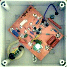
 synthetic
"resistor"
synthetic
"resistor"
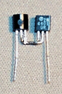
A schematic of the current buffer is available here . Please note that in my schematic, R3, the 100Meg resistor, is replaced with a synthetic resistor in this application. Scott Fusare introduced me to this technique, and he says it was suggested to him by Ken Walsh. This is an economical approach to creating an extremely high value resistor.
Initially, I used a 2N3904 pair that Scott sent me to test. A pair I made made from 2N4401 transistors is shown to the right. In my tests, the 2N4401 tests at about 100 gigaohms – and initial field tests look promising. However, Scott warns that too high a value can result in severe problems with fair weather currents causing significant offset voltages on the FET gate. He says that the brand of transistor seems to make a big difference. For example, he has measured Motorola 2N3904s at over a teraohm.
Note that this kind of resistor is definitely NOT a replacement for a real, good quality resistor (e.g. Victoreen). So, don't try to run these "resistors" at high voltages. But they should work adequately for home-brew ion chamber amplifiers and the like. Scott Fusare details to a friend how to measure the value of these resistors – effectively in circuit – here. I really appreciate Scott sharing this material. Finally, this approach is recommended only if you don't have a 10 to 100 gigaohm resistor handy. If you do, use it!
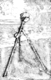
The antenna/buffer is shown below.
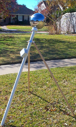
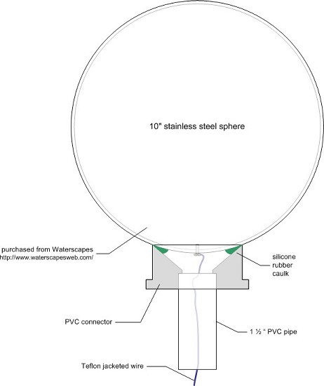
The main support is 1 1/2" PVC pipe. The ball with the pipe is 6' long. Deployed, the unit stands over 5' tall. The buffer is housed in the small plastic box. The 10" stainless steel gazing ball is mounted on a PVC adapter with silicone rubber caulk. A teflon jacketed wire through the PVC pipe connects the ball to the buffer. The wire to the ball is attached by a screw that goes into a hole tapped in the ball. The screw connection is treated with GB Ox-Gard in hopes of minimizing future oxidation. The legs are hoe handles drilled on one end to accept the screws. Details of the arrangement are shown below.
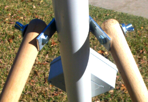

The broomsticks are drilled and mounted via screws with wing nuts to an aluminum bracket made from 1" x 1/8" flat bar stock. The bracket is formed around the PVC tube and drilled to accept the broomstick screws and a mounting screw. Once in place, the bracket is further secured using JB Weld. A diagram detailing the ball mount is shown below.
Performance
Currently, the signal is run through an AC-coupled opamp buffer that translates the single-ended signal into a dual power supply to redefine the ground for further processing. This also provides some high pass filtering, which is desireable to help manage near DC transients from any movement near the ball (cats, crows, people, trees, etc.) Right now, I am running the signal through a Wavetek 852 dual filter, set to cut off everything above about 37 Hz (at 96 db per octave!) This unit also provides 40 db of gain. I monitor the signal out on my oscilloscope and feed it into Gram on my PC.
Below is an example of a recording made in front of my house at a quiet moment. It was completed at just after 10PM CST on 11/24/01. Obvious is an almost always present signal at about 25 Hz. You can also see a signal at about 36 Hz that disappears right at 1000 seconds into the recording. Other examples are available for download from this page .

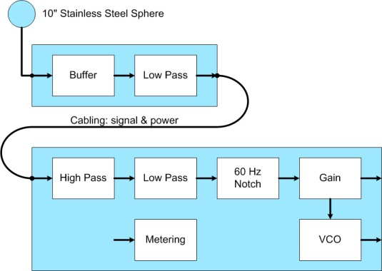
System Design - Planned
The design for the next phase is shown below.
A number of references are available on the links page here.