
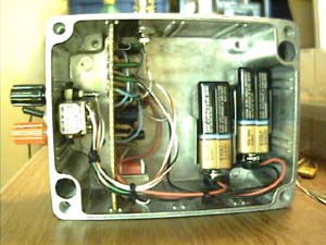


Update: (7/10/00) Here is the B-Field receiver in a box. looks a lot
better then the breadboard!
This receiver was used for Transmitting Project
#2
Update: (6/1/00) I have made a few changes to the circuit, added an active low-pass filter section with the unused portion of the LM324 op-amp. Also, I improved the gain somewhat with a lower impedance transformer.
Click here for the updated schematic diagram
Here is a Schematic Diagram of a B-Field receiver I designed in May
of 2000. It uses a single turn loop for the antenna, however, it will work
with multi-turn loops. The frequency response seems to lower as turns are
added to the loop. A single turn of 20 gauge wire 300 feet long works very
well. Even 100 feet of a loop has a decent amount of gain. The main drawback
is the sensitivity of this system, you must seek out a site VERY far from
ac, it can hear ac several times better than E-field receivers. You can
also orient the antenna for an ac null. Low pass filtering can be added
to the circuitry, if an LM324 op amp is used, there are a couple of unused
stages that a filter can be built out of. This unit provides a LINE LEVEL
output, not mic level output. For stereo reception of VLF, first,
you must build two of these receivers, second, you have to orient the antennas
of each unit at 90 degree angles from each other. Each antenna should be
the same length and at equal height. You can hear some recordings from
this receiver setup on the VLF recordings
page.
click here for the Schematic Diagram


B-Field Receiver on breadboard
Just finished an improved version of this unit, click here to see it.
I finally finished drawing the schematic for my latest Receiver, the connection between the antenna and the output may be omitted, the purpose of it is to combine RF with the VLF output so my WWV receiver can use the Antenna with the VLF receiver, and still be isolated from each other. The mixer unit divides the two signals into separete outputs.
Revision: The Inductor values have been corrected on the schematic.
here they are:

