
![]()
Translation tools from SYSTRAN
Translate your documents within seconds with Try SYSTRAN Personal!
LAST MODIFIED:
Monday, 25-Mar-2002 22:11:35 EST
Antennas, to quote a friend, are one of life's eternal mysteries. "All I'm totally certain of is that any antenna is better than no antenna and the antenna should preferably erected as high and be as long as is possible or desirable". Here we will discuss the very basics of antennas. Remember that thought: these are just some introductory antenna basics. Each type of antenna will eventually have its own page. In particular I would commend everyone to read my page on earth dangers. I think it ought to be compulsory reading.
The most basic antenna is called "a quarter wave vertical", it is a quarter wavelength long and is a vertical radiator. Typical examples of this type would be seen installed on motor vehicles for two way communications. Technically the most basic antenna is an "isotropic radiator". This is a mythical antenna which radiates in all directions as does the light from a lamp bulb. It is the standard against which we sometimes compare other antennas.
This type of antenna relies upon an "artificial ground" of either drooping radials or a car body to act as ground. Sometimes the antenna is worked against an actual ground - see later.
Depending upon how the antenna is orientated physically determines it's polarisation. An antenna erected vertically is said to be "vertically polarised" while an antenna erected horizontally is said (not so surprising) to be "horizontally polarised". Other specialised antennas exist with "cross polarisation", having both vertical and horizontal components and we can have "circular polarisation".
Note that when a signal is transmitted at one polarisation but received at a different polarisation there exists a great many decibels of loss.
This is quite significant and is often taken advantage of when TV channels and other services are allocated. If there is a chance of co-channel interference then the license will stipulate a different polarisation. Have you ever noticed vertical and horizontal TV antennas in some areas. Now you know why.
Technically, antenna impedance is the ratio at any given point in the antenna of voltage to current at that point. Depending upon height above ground, the influence of surrounding objects and other factors, our quarter wave antenna with a near perfect ground exhibits a nominal input impedance of around 36 ohms. A half wave dipole antenna is nominally 75 ohms while a half wave folded dipole antenna is nominally 300 ohms. The two previous examples indicate why we have 75 ohm coaxial cable and 300 ohm ribbon line for TV antennas.
A quarter wave antenna with drooping quarter wave radials exhibits a nominal 50 ohms impedance, one reason for the existence of 50 ohm coaxial cable.
The quarter wave vertical antenna is usually the simplest to construct and erect although I know a great many people who would dispute that statement. In this context I am speaking of people (the majority) who have limited space to erect an antenna.
Figure 1. - a quarter wave vertical antenna with drooping radials
In figure 1 we have depicted a quarter wave vertical antenna with drooping radials which would be about 45 degrees from horizontal. These 45 degree drooping radials simulate an artificial ground and lead to an antenna impedance of about 50 ohms.
A quarter wave vertical antenna could also be erected directly on the ground and indeed many AM radio transmitting towers accomplish this especially where there is suitable marshy ground noted for good conductivity. An AM radio transmitting tower of a quarter wave length erected for say 810 Khz in the AM band would have a length of nearly 88 metres (288') in height.
The formula for quarter wave is L = 71.25 metres / freq (mhz) and in feet L = 234 / freq (mhz). Note the variance from the standard wavelength formula of 300 / freq. This is because we allow for "velocity factor" of 5% and our wavelength formula becomes 285 / freq.
When a quarter wave antenna is erected and "worked" against a good rf ground (called a Marconi Antenna) the earth provides a "mirror" image of the missing half of the desired half wave antenna.
Figure 2. - a marconi antenna
In figure 2 above where I have depicted the Marconi Antenna imagine a duplicate of the quarter wave antenna being in existence from the top of the ground and extending down the page. This is the mirror image.
The half wave dipole antenna becomes quite common where space permits. It can be erected vertically but is more often than not erected horizontally for practical reasons. I gave quite a good example of its use in my paper on
radio
telescopes from my original site. I have reproduced it in figure 3 below.
Figure 3. - half wave dipole antenna
This particular antenna was dimensioned for use at 30 Mhz. You will note that the left and right hand halves are merely quarter wave sections determined by the formula given earlier. The input impedance (affected by many factors) is nominally 50 ohms.
As with all antennas, the height above ground and proximity to other objects such as buildings, trees, guttering etc. play an important part. However, reality says we must live with what we can achieve in the real world notwithstanding what theory may say.
People erect half wave dipoles in attics constructed of fine gauge wire - far from ideal BUT they get reasonable results by living with less than the "ideal". A lesson in life we should always remember in more ways than one.
The folded dipole antenna is probably only ever seen as a TV antenna. It exhibits an impedance of 300 ohms whereas a half wave dipole is 75 ohms and I'm certain someone will be alert enough to ask "why 75 ohms, if figure 3 above is 50 ohms?".
Within the limits of my artistic skills I have depicted a folded dipole antenna below.
Figure 4. - half wave folded dipole
One powerful advantage of a folded dipole antenna is that is has a wide bandwidth, in fact a one octave bandwidth. This is the reason it was often used as a TV antenna for multi channel use. Folded dipole antennas were mainly used in conjuction with Yagi antennas.
The Yagi antenna or more correctly, the Yagi - Uda antenna was developed by Japanese scientists in the 1930's. It consists of a half wave dipole (sometimes a folded one, sometimes not), a rear "reflector" and may or may not have one or more forward "directors". These are collectively referred to as the "elements".
Figure 5. - the Yagi antenna
In figure 5 above I have reprinted a UHF Yagi antenna array from my radio telescopes page. You will note, not altogther clearly.
However in figure 6 below, which happens to be a photograph of a neighbour's TV antenna, I can clearly point out details of a practical Yagi antenna.
This particular antenna has been optimised for dual band operation. It is designed to pick up both VHF and UHF transmissions. Because I live in a regional of NSW in Australia, TV antennas tend to be single channel types designed either for higher gain or better directivity. Different examples will be presented later.
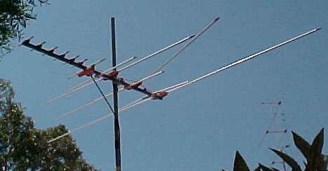
Figure 6. - a practical Yagi TV antenna
Looking from left to right on this dual band Yagi we have six UHF "director" elements which improve gain and directivity. Next is the UHF half wave dipole which could have easily been a folded dipole but is in fact a plain half wave dipole.
The next three much longer elements form a "phased array" for the VHF band. I am unsure of the function of the three remaining smaller elements, information is quite scant here but one would certainly be a UHF "reflector". Likely the other two also fulfill this function also.
Note: This is a horizontally polarised antenna and is orientated roughly NNW, 315 degrees.
You will notice the effect of very strong storms from the sea have had in bending the second larger elements. In my locality storms are a problem but not as much as roosting parrots such as large sulphur crested cockatoos.
In the photograph in figure 7 below you can see a classic UHF Yagi antenna. It has a total of nineteen "elements" comprising seventeen "directors", a fancy folded dipole with a "low-noise mast head amplifier" and a "reflector".
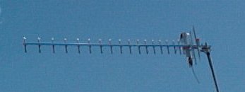
Figure 7. - a vertically polarised UHF Yagi antenna
This is a a vertically polarised UHF Yagi antenna and it is orientated WSW or 225 degrees. It does in fact pick up signals about 100 Km or 60 mile distant from Sydney.
This is the very same antenna I was suggesting to be used in the radio telescope array I depicted in figure 5 above.
The majority of TV antennas in my retirement village are stacked half wave dipoles. These consist of four sets of a half wave dipole and a reflector only, but mounted one above another. These antennas owe their origin to the days we only had VHF TV in the area. Surprising with the introduction of UHF they continued to function quite well in picking up UHF as well. This particular antenna is my one and I've never had the need to go to a UHF antenna. The top two elements normally are home to roosting "top knot" pidgeons, a pigeon native to Australia.
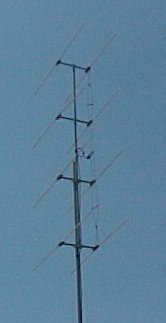
Figure 8. - four stacked half wave dipoles collinear antenna
To the left of the photograph are the "reflectors" and to the right are the four vertically stacked half wave dipoles. The wires connecting each half wave dipole are done in a "phased way". This comprises a collinear antenna array and is so arranged for improved gain.
Note this antenna is horizontally polarised.
The loop antenna comes in an amazing number of configurations. It is a "small space" antenna and although extremely inefficient is capable of surprising results. In receiving applications the loop antenna works on the principle of the "differences" in voltages induced by the current flowing in the sides of the antenna. As you might imagine these difference voltages can be extremely minute in amplitude and any loop antenna usually requires an associated amplifier capable of at least 25 dB power gain following it.
One example of a shielded loop antenna is taken from my tutorial on mobius winding techniques is shown in figure 9 below.
Figure 9. - mobius winding of a loop antenna
This is the general loop antenna which has one interesting characteristic. It responds well to signals arriving in one direction, either from the left hand side of your computer screen or the right hand side of your computer screen for the loop shown in figure 9 (b) above. Signals from either your face or from behind your monitor would produce equal signal currents from both sides of the loop and consequently produce no difference voltage output.
Technically speaking, a loop antenna responds to the magnetic field rather than the electric field.
Rather than being omnidirectional (as a whip antenna would be) the loop antenna responds to the cosine of the angle between its face and the direction of arrival of the electromagnetic wave. This actually produces a figure eight pattern, which for receiving presents no probems. The addition of a small whip antenna in conjuction with proper phasing allows the direction ambiguity to be resolved and we have an antenna relatively ideal for direction finding.
The most common loop antenna you will encounter is the loopstick antenna built into portable receivers. In figure 10 below is the AM and shortwave loopstick antenna in a Sanyo model RP2127 MW / SW receiver (it's old).
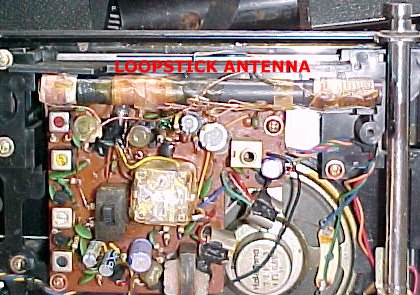
Figure 10. - AM and shortwave loopstick antenna
The AM and shortwave loopstick antenna is located in the upper half under the words "loopstick antenna". For greater efficiency and size reduction, a loopstick antenna is wound on a "ferrite" rod. This particular one happens to be circular but you may encounter ones which are rectangular.
As an experiment you might, if you have a loopstick antenna radio available, tune to a weak station and rotate the radio around 360 degrees. You should notice two points 180 degrees apart where the signals seem to be the strongest and similarly notice two other points 180 degrees apart where the signals seem to be the weakest - these are called "nulls". This is the aid to "Radio Direction Finding - RDF"
Now here is a little gem. The terminated tilted folded dipole is bound to give a "rush of blood to the head" of any avid DX'er (that means long distance -dx- receive / transmit enthusiast).
The terminated tilted folded dipole is somewhat similar to the half wave folded dipole in figure 4 above yet the claims for its performance are quite astonishing. The terminated tilted folded dipole is claimed to have a bandwidth of something like 5 or 6 to one, been extensively tested and adopted by the US Navy, easy to construct from readily available materials and, has a feedpoint impedance of around 300 ohms.
Figure 11. - Terminated Tilted Folded Dipole
The dimensions "A" and "B" for a terminated tilted folded dipole are as follows:
Each leg "A" = [ 2 X pi ( 15.25 / Fo )] and;
Distance "B" = [ 2 X pi ( 0.915 / Fo )]
where in both instances 2 X pi = 6.28 and Fo is in Mhz.
There seems to be some debate about the exact formula, my friend L. B. Cebik (see next) says:
"The "Wide-Long" version coincides with standard construction formulations, since the antenna is about 300/F(MHz) long and 10/F(MHz) wide. (Excessively fussy cutting formulas for this antenna are largely superfluous, since strict resonance is not in question)."
My friend L. B. Cebik (see later) has modeled this antenna. Modeling the T2FD
Further comprehensive details on the claims for the amazing terminated tilted folded dipole antenna and its construction can be found at:
http://www.hard-core-dx.com/nordicdx/antenna/wire/t2fd.html
The reason there has been emphasis on TV antennas is simply because nearly everyone can look at examples in their own locality for comparison. At TV frequencies the physical dimensions are such I can offer practical examples with photographs.
The same basic principles apply at HF and LF although physical sizes tend to be totally impractical.
As time permits I will flesh out more and more in depth articles on all these antennas and even more types not even mentioned here. This page alone comprises well over 2,000 words so you can imagine the job ahead with competing demands on my time. Meanwhile consider this important publication on antennas.
Meanwhile I would also suggest that you take a good look at L.B. Cebik 's W4RNL great web site. My good friend LB is "THE antenna guru".

![]() ORDER - U.S.A. NOWBuilding and Using Baluns and Ununs : Practical Designs for the Experimenter - by Dr. Jerry Sevick, W2FMI.
ORDER - U.S.A. NOWBuilding and Using Baluns and Ununs : Practical Designs for the Experimenter - by Dr. Jerry Sevick, W2FMI.
baluns
earth dangers
wavelength
decibels
impedance
mobius winding techniques
radio telescopes
NEW! - How to link directly to this page
Want to create a page link to me from your site? It couldn't be easier. No HTML knowledge required; even the technophobes can do it. All you need to do is copy and paste, the following code. All links are greatly appreciated; I sincerely thank you for your support.
Copy and paste the following code for a text link:
and it should appear like this:
<a href="http://www.electronics-tutorials.com/antennas/antenna-basics.htm" target="_top">visit VK2TIP's Antenna Basics Page</a>
visit VK2TIP's Antenna Basics Page

This site is hosted at WebWizards.Net for better value.
![]()
Please send me your valuable comments and suggestions! Tell your friends, tell a news group, tell your favourite magazine, heck tell the world!
Absolutely essential to keeping abreast of new and updated electronics tutorials is our comments or subscribe to our highly regarded FREE monthly newsletter form. Unsubscribe any time you like. You can view immediate past issues here to see if it is to your liking.
the author Ian C. Purdie, VK2TIP of www.electronics-tutorials.com asserts the moral right to
be identified as the author of this web site and all contents herein. Copyright © 2000, all rights reserved. See copying and links.
These electronic tutorials are provided for individual private use and the author assumes no liability whatsoever for the application, use, misuse, of any of these projects or electronics tutorials that may result in the direct or indirect damage or loss that comes from these projects or tutorials. All materials are provided for free private and public use.
Commercial use prohibited without prior written permission from www.electronics-tutorials.com.
Copyright © 2000 - 2001 - 2002, all rights reserved. URL - http://www.electronics-tutorials.com/antennas/antenna-basics.htm
Updated 25th March, 2002
webmaster@electronics-tutorials.com