Short Vertical Antennas and Ground Systems - VK1BRH
* Copyright (c) Ralph Holland 1995, Copyright ( c) Amateur Radio 1995.
Introduction
There have been a number of articles discussing the merits or otherwise of various types of ground systems. The analysis of such systems is complicated by the facts that practical ground system parameters are difficult to quantify, antennas are situated in less than ideal locations, and literature, that may provide insight into what is happening, often does not present the information in a practical or applicable form. Often the reader is left to extrapolate beyond the bounds of presented data and arrive at the incorrect conclusion. Some folk-lore has been generated as a result of these types of difficulty; one such lore is 'the higher the better', which is an over-generalisation if said without qualification.
Activities
I am interested in 160m operation; it is a challenge to develop reasonably efficient antennas for this'top band'. I am also interested in mobile and portable work so I constructed antennas and experimented a bit. It was difficult to quantify the results and performing alterations was rather tedious, so I turned to computer simulation.
After performing several different simulations I developed the feeling that it should be possible to optimise the efficiency of an antenna by altering its earth currents and through the interactions with the mutual impedance of the antenna and its ground image. This turned out to be a very fruitful study, although I initially thought the results were dubious!
Simulations
Fortunately non-ideal antennas have been under analysis by various organisations and many papers have been written covering the theoretical aspects. One organisation of note is the Lawrence Livermore National Laboratory (LLNL), which was commissioned by the U.S. Department of Defence to perform theoretical and practical analysis of various antenna systems. Some of this material has been declassified and is now publicly available.
During this period several computer-based antenna simulation programs were developed; of note is the Numeric Electromagnetic Code (MINI-NEC, NEC-2 and NEC-3 and now NEC-4).
NEC-81 is the name of the earlier PC version of NEC-2. NEC-81, NEC-2 and MINI-NEC are available through the Applied Computation Electromagnetic Society (ACES); contact Dr R.W. Adler, ECE Department, Code EC/AB, Naval Post Graduate School, 833 Dyer Rd, Rm. 437, Monterey California, 93943-5121, U.S.A or Fax 1 408 649 0300 or E-mail 554-1304@mcimail.com, for the conditions, membership and handling fees if you want to obtain these programs.
Post publication note: public domain software now available at Unofficial NEC2 pages.
NEC-2 can model antennas in proximity to lossy ground. The lossy ground analysis is based on work by Sommerfeld; and appears to yield realistic feed-point impedances and reasonably quantifiable losses.
System Performance
The simulation goal was to determine the relative merits of elevated groundplanes for short vertical systems, ie up to 0.25 wavelengths.
Traditionally, it has been convenient to measure the feed-point impedance of the lossy antenna system and compare it with the ideal (theoretical) case. The feedpoint resistance for vertical antennas is called the base resistance (Rb); Rb is composed of the useful radiation resistance (Rr) and the collective loss resistance (Rl). Rr can be evaluated theoretically, it would be the Rb of an antenna over ideal infinite ground.
Rr can be obtained by the additional simulation of the ideal ground model, effectively doubling the simulation time to obtain results. Fortunately, NEC-2 calculates the amount of power radiated around the region of the antenna and divides this by the applied power. This ratio depends upon whether the model is simulated in free space or over ground.
The radiation region of an antenna in free-space is a solid sphere so this ratio should be unity. The radiation region is a hemi-sphere when the antenna is situated against an infinite ground, in which case the value should be close to two; this is due to the ground reflecting power into the upper hemisphere (effectively up to 3dB of gain). This ratio is a also used to gauge the stability of the model; if its value greatly exceeds the expected value then the model has failed.
Post publication note: an antenna may exhibit up to 6dB of gain over its free-space radiation pattern due to ground refelection in some directions.
It is a simple means to use this power ratio to determine the antenna's efficiency. Note that the radiation resistance can be dervied via: Rr = Rb / efficiency; I used this analysis to cross-check the results of some simulations.
Results
The term displacement is employed for the height of the groundplane above ground; this avoids confusion with antenna element lengths. All lengths, heights and displacements are measured in wavelengths (lamda) unless otherwise indicated.
Resistance versus Groundplane Displacement
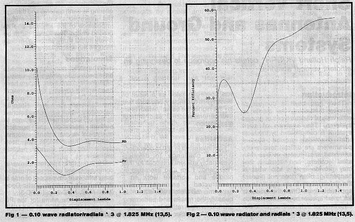
Figure 1 shows the effects of various displacements upon a 0.10 wavelength vertical antenna with three 0.10 wavelength radials at 1.825MHz. I chose the average ground parameters: relative dielectric constant 13 and conductivity of 5 milli-Siemens per meter (13,5); which are typical for dry clay and indicative of the Canberra region.
Note that the Rb is high at zero displacement, much higher than Rr, so Rb is largely composed of loss resistance at this point, and the antenna is primarily heating the ground! Notice how difficult it is to determine the optimal displacement from the Rb and Rr curves on this graph.
Efficiency versus Displacement
Figure 2 shows the antenna's efficiency over the same range. Notice that there is an initial peak at fairly low displacements. Advantage will be taken of this effect.
Displaced Antennas versus the Number of Radials
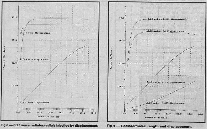
Figure 3 is the comparison between the conventional groundplane, situated on or in the ground, and the elevated groundplane. The simulation parameters are 1.825Mhz, 0.25 wave radiator and radials, and ground parameters (13,5). The integer simulation points are joined to form curves (I did not actually simulate a non-integral number of radials).
Notice that the elevated curves are asymptotic to a horizontal line about 37 percent efficiency. The elevated curves are more than satisfactory at the three to four radial mark; the traditional ground screen doesn't even get near this at 32 radials. Recall that the typically quoted commercial design figure is to strive for 120 ground-based radials.
Variable Radiator, Radial Length and Displacement versus Number of Radials
Figure 4 illustrates the effect of radiator and radial lengths. The simulation is at 1.82MHz and for ground parameters (13,5). The top curves represent the elevated groundplane, while the bottom curves are for ground-based antennas.
Variable Radiator and Radial Length at a constant Displacement
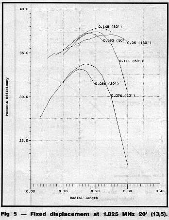
Figure 5 is the graph for a 1.825Mhz vertical, which was simulated for Eric, VK3AX. This simulation was based on 3 radials mounted at 20' (woolshed height) over typical clay soil (13,5). We were interested in the affect of the antenna height and radial length. The radiator length was labelled on the graph in wavelengths and feet. You will notice that short radiators performed quite well with radial lengths of 0.15 wavelengths and appear worthwhile constructing. When the radiators are lengthened from 0.06 wavelengths to 0.15 wavelengths, the efficiency improves by 5 percent; not much gain results from extending radiators up to the full 0.25 wavelength, in fact, this length was noticeably less efficient than the 0.148 wavelength radiator. In all curves there is an optimal radiator and radial length. Notice how the optimal radial lengths are noticeably less than a quarter wave for the shorter radiators.
Efficiency of Elevated Groundplane and Frequency
Figure 6 shows the effects of changing frequency. The analysis has been performed for the 160m, 80m, 40m and 20m bands so you can apply these results to your favourite band. All radiator and radial lengths were 0.25 wavelength, in all cases only three radials were employed.
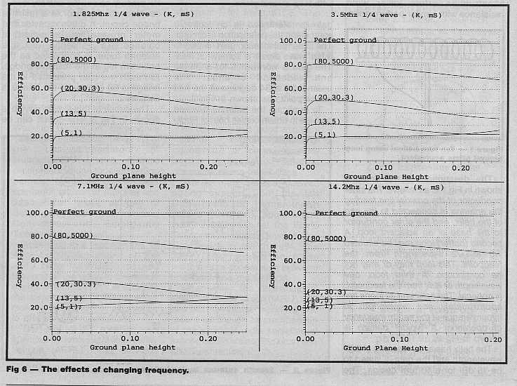
Each curve is labelled by its ground parameters. The curves could be named from top-to-bottom as: Perfect, Sea water, Good, Average, and Poor respectively. Recall that the Average curve, labelled (13,5) is indicative of the dry clay soils.
Notice that the curves peak between 0.002 and 0.05 wavelengths displacement. A more difficult observation, due to the scale of the graphs, is that the curves point steeply towards zero efficiency at zero height (you can obtain a better indication from Figure 2).
Conclusions
From the Figures it is obvious that the simulated antenna efficiency declines dramatically when the groundplane displacement approaches zero.
With three or more radials the radial length is more important to the overall efficiency than the number or radials, with a few exceptions. An interesting side-effect I noticed is that under certain conditions a vertical antenna with one radial was substantially more efficient than an antenna with any other number of radials; such an hybrid antenna has been studied before and been applied in marine and land-based systems. (I would like to present the analysis of this and horizontal antennas at a later stage.)
Points to remember:
I have also performed simulations for elevated groundplanes with an underlying secondary ground screen placed on the ground. It is detrimental to connect the elevated groundplane to this form of lower ground system. Note the recommended commercial practice to terminate radial systems with a ground stake - I would highly recommend against such practice; the situation is made even worse if the ground stake is under the feedpoint rather than at the ends of the screen.
I originally thought that this grounding anomaly was an artefact of NEC-2, but I have subsequently read the preliminary publication 'Recent Advances to NEC: Applications and Validation' by G. J. Burke, 1989, which investigated these effects and others; he used the new improved and classified NEC-4 to model situations for several typical broadcast antennas and antennas below the ground. Burke found, to my surprise, and others, that the recommended grounding practices are detrimental. Burke's findings were based on the relative communication efficiency (RCE) of the antenna measured in terms of field strength at some distance outside the near field, a more appropriate value, rather than the efficiency figure I employed.
Bibliography
The MINI-NEC and NEC programs are based on the Method-of-Moments (MoM); you can find a description of this method in " Antennas, Second Edition", by John D. Kraus, McGraw Hill 1988.
Another book, which describes the foundation of the technique, is "
Field
Computation by Moment Methods", by R.F.Harrington, McGraw
Hill 1961.
Post publication note: This classic has been reprinted by the
IEEE and is available at
a discont if you are a member.
The hybrid vertical - horizontal marine dipole, developed by VK3AM, is described in "Hf Antennas for All Locations", by L.A. Moxon, G6XN, on page 154.
The "ARRL Antenna Compendium", Volumes One and Two, (now Three, Four and Five) are also interesting reading for antenna construction and modelling.
The book review "Computational Electromagnetics: Frequency Domain Method of Moments" by Edmund K. Miller, Louis Medgyesi-Mitschang, and Edward H. Newman was extracted and printed in an ACES newsletter. The extract stated that the review contains 528 pages and recommends several books.
One book of recent publication is: "Generalised Moment Methods in Electromagnetics", by J.H. Wang, John Wiley and Sons, NY, 1991. I believe this would be for the serious MoM enthusiast.
* Terms
This article was first published in Amateur Radio Volume 63 No 10, October 1995. 'Amateur Radio' is the journal of the Wireless Institute of Australia. Both the author and the WIA hold copyright. No reproduction is permitted for commercial purposes without express permission of the copyright holders. (mailto:ralph@arising.com.au to contact the author). This article was updated with post publication notes on 28 Nov 1998, and several hypertext links have been added for your convenience.